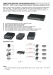
1
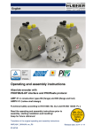
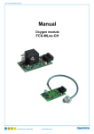
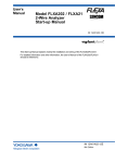
User’s
Manual
YOKOGAWA
Model FC20
Cleaning Systems
IM 12B6V1-01E-E
5th
4th edition
edition
2
TABLE OF CONTENTS
1. INTRODUCTION ............................................................................................................3
1-1. General...................................................................................................................3
1-2. Cleaning system .....................................................................................................3
1-3. Selection criteria .....................................................................................................3
1-4. Compatibility...........................................................................................................4
1-5. Warranty and service..............................................................................................4
2. SPECIFICATIONS ..........................................................................................................5
2-1. Brush cleaning .......................................................................................................5
2-2. Chemical cleaning ..................................................................................................6
2-3. Models and suffix codes.........................................................................................6
3. DESCRIPTION ...............................................................................................................7
3-1. Brush cleaning system ...........................................................................................7
3-1-1. General ...............................................................................................................7
3-1-2. Driving mechanism (electric) ................................................................................7
3-1-3. Driving mechanism (pneumatic ..........................................................................7
4. INSTALLATION ..............................................................................................................8
4-1. Unpacking and checking ........................................................................................8
4-2. Installation site........................................................................................................8
4-3. Brush cleaning .......................................................................................................9
4-3-1. Brush holder .......................................................................................................9
4-3-2. Driving mechanism (electric) ................................................................................9
4-3-3. Wiring the driving mechanism (electric)...............................................................10
4-3-4. Driving mechanism (pneumatic)..........................................................................10
4-3-5. Control unit for driving mechanism (pneumatic) ..................................................10
4-3-6. Connecting control and driving mechanism (pneumatic) .....................................11
4-4. Chemical cleaning ..................................................................................................11
4-4-1. Spray unit............................................................................................................11
4-4-2. Connecting the spray unit ...................................................................................11
5. ADJUSTMENTS ...........................................................................................................12
5-1. Brush cleaning .....................................................................................................12
5-1-1. Brush adjustments ............................................................................................12
5-1-2. Driving mechanism (pneumatic).........................................................................12
6. DIMENSIONS ...............................................................................................................13
6-1. Spare parts list .....................................................................................................15
7. INSTALLATION OF CHEMICAL CLEANING SYSTEMS HCN 2/3/4/F .....................16
IM 12B6V1-01E-E
3
1. INTRODUCTION
1-1. General
For industrial applications and particularly
for automatic process measurements, it is
of the greatest importance that the
sensitive part of a glass electrode and the
flow diaphragm of a reference electrode
are kept clean. Often it is not practical to
interrupt a process for cleaning the
electrodes, an accurate indication is
required over a long period, replacing the
electrodes is difficult, etc.
There, an automatic cleaning mechanism
may be the solution.
YOKOGAWA manufactures two different
cleaning systems for pH and/or ORP
(Redox) measurements:
- chemical cleaning
- brush cleaning
a. pneumatically driven
b. electrically driven
CONTROL
UNIT
TUBING
PISTON
UNIT
O-rings
(11x3)
O-RINGS
BRUSH HOLDER
K1547PP
(spare tubing, EPDM)
Fig. 1 Brush Cleaning
(pneumatical driven)
Fig. 2 Brush Cleaning
(electral driven)
1-2. Cleaning systems
The cleaning elements have standardised
dimensions for mounting in flow and/or
Model
FF20-P43
FF20-F43
FF20-S43
FD20-P47
FD20-F47
FD20-S47
FS20-V42
FS20-S43
Type
Flow fitting
Flow fitting
Flow fitting
Immersion fitting
Immersion fitting
Immersion fitting
Subassembly flow fitting
Subassembly flow fitting
immersion fittings. These fittings have the
following model codes:
Material
Polypropylene
Polyvinylidene fluoride
Stainless steel
Polypropylene
Polyvinylidene fluoride
Stainless steel
PVC
Stainless steel
Detailed specifications of the fittings are on separate sheets
(see GS 12B6K1 and GS 12B6K2)
IM12B6V1-01E-E
4
1-3. Selection criteria
The table below indicates the recommended
cleaning method for your specific application.
Selection criteria
Applications with:
Oils, fats
Resins (wood, pulp)
Emulsions of latex
Fibers (paper, textile)
Crystalline precipations
(carbonates)
Amorpheus precipations
(hydroxides)
Mechanical
Brush
Chemical
Acid
Base
X
X
X
X
XX
X
XX
1-4. Compatibility
The Yokogawa analysers model number
PH402 and PH450 is equipped with a wash
timer function to control the chemical
cleaning system. Detailed information is
given on sheet and GS 12B6B3-E-E
(PH402) and GS 12B6B5-E-E (PH450).
1-5. Warranty and service
Products and parts are warranted to be free
from defects in workmanship and material
under normal use and service for a period
of typically twelve months from the date of
shipment by manufacturer. The sales
organisation has the possibility to deviate
from this typical warranty period and the
actual terms and conditions as specified in
the sales order must be consulted.
Damages, caused by wear and tear,
inadequate maintenance, corrosion and
attack by chemical processes are excluded
from this warranty coverage.
Any defective goods need to be sent to
the service of the sales organisation for
repair or replacement and the returned
material should be accompanied by a letter
of transmittal, which should include the
following information:
1. Part number, model code and serial
number
2. Date and number of sales order
IM 12B6V1-01E-E
3. Length of time of service and type of
service
4. Description of the faulty operation of the
device and the circumstances of the
failure
5. Pressure, temperature, process
compensation and all other process
conditions or environmental circumstances which are related to the installation and possibly failure of the device
6. Statement as to whether warranty or
non-warranty service is requested
7. Complete shipping and billing
instructions for return of material and
name, phone number of contact person
that can be approached for further
information.
The returned goods that have been in
contact with process fluids must be
detoxified and disinfected prior to shipment
for the health and safety of our employees.
Material Safety Data sheets must be
included for all components of the
processes in which the cleaning system
has been used.
The shipping address where the goods
have been returned is specified on the
original sales order or on the back page of
this manual.
5
2. SPECIFCATIONS
2-1. Brush cleaning
Brush holder
Material
- Body
- Brush
Process conditions
Weight
Mounting
: a. Stainless steel
b. Epoxy
c. Silicone rubber
d. Epoxy resin
: Horse hair (in PVDF holder)
: Max. 1 MPa (10 bar) at 100 °C
: Approx. 120 g
: In Yokogawa flow or immersion fittings (4-hole)
Driving mechanism (electrical)
Supply (see note)
- Voltage
: 24 V AC (± 10 %)
- Frequency
: 50/60 Hz
- Consumption
: Max. 4 VA
Cleaning frequency
: 2 strokes per minute
Angle
: Rotation of 40 ° (swing)
Electrical connection
- Connector
: Gold plated spring O-connector (for standard Yokogawa
electrode cable Model WU20-PC )
- Screw thread
: 1/4” BSPP
Material
- Driving system
: Stainless steel AISI 316
- Driving shaft
: Stainless steel AISI 316
- Cap
: Silicone rubber
- Connector holder
: Polyvinylidene fluoride (PVDF)
- Mounting nut
: Ryton R4
Weight
: Approx. 1 kg
Driving Mechanism (pneumatic)
Piston unit
Air supply
: Adjustable (via the connected control unit)
Cleaning frequency
: 1/4.... 2 strokes per minute (adjustable on the control unit)
Angle
: Rotation 40°
Air connectors
: ø4 mm (external) (IN1 and IN2)
Material
- Body
: Brass
- Mounting gland
: Stainless steel AISI 316
Weight
: Approx. 1 kg
Control unit
Air supply
Ambient temp. range
Housing
- Material
- Entries
- Dimensions
- Mounting
- Weight
: 140 kPa (1,4 bar) pressurised air
: -10 to 60 °C
:
:
:
:
Aluminium case with chemical resistant lacquer (IP65)
Air connector ø6 mm
See dimensional drawings
Wall mounting (for fixing dimensions, see dimensional
drawings)
: Approx. 2,5 kg
IM12B6V1-01E-E
6
Supply (see note)
- Voltage
- Frequency
- Consumption
Cleaning frequency
Angle
Electrical connection
- Connector
- Screw thread
Material
- Driving system
- Driving shaft
- Cap
- Connector holder
- Mounting nut
Weight
:
:
:
:
:
24 V AC (± 10 %)
50/60 Hz
Max. 4 VA
2 strokes per minute
Rotation of 40° (swing)
: Gold plated spring O-connector (for standard Yokogawa
electrode cable, Model WU20)
: 1/4” BSPP
:
:
:
:
:
:
Stainless steel AISI 316
Stainless steel AISI 316
Silicone rubber
Polyvinylidene fluoride (PVDF)
Ryton R4
Approx. 1 kg
2-3. Chemical cleaning system
Features
• The EXA pH450 analyser has a built-in timer and HOLD circuit.
• Built-in (no return) nozzle to prevent penetration of the process liquid into the cleaning system.
Materials
- Nozzle
- O-rings
- Mounting set
- Tubing
- Process cond.
Mounting
K1547PA
K1547PA
K1547PB
K1547PJ
:
:
:
:
:
Hastelloy
EPDM rubber
Stainless steel
1/4” (OD Ø) Nylon tubing
Max. 1 MPa (10 bar) at 100 ºC
: /HCN2, 2-hole flow-, insertion fitting (PH20)
: /HCN3, 3-hole flow-, insertion-, immersion fitting
: /HCN4, 4-hole flow-, insertion-, immersion fitting
: /HCNF, back-end mounting on FU20/PH20
2-4. Model- and suffix codes
Mechanical cleaning system
Model Suffix Options
Description
code code
FC20
Cleaning system
Design -VE
Brush cleaning
(electrical driven)
-VP
Brush cleaning
(pneumatical driven)
Options
/T
10 mtr. nylon tubing
6.35 mm OD (1/4”)
Spareparts Chemical cleaning system
Type
Description
K1547PA
Complete cleaning system HCN2, HCN3
K1547PB
Complete cleaning system HCN4
K1547PJ
Complete cleaning system HCNF for back-end
mounting on FU20/PH20
K1547PP
EPDM spraying valve HCNX nozzle (5 sets)
IM 12B6V1-01E-E
7
3. Description
3-1. Brush cleaning system
3-1-1. General
The brush in this cleaning system
periodically strikes along the sensitive
membrane of the measuring electrode, so
that this part is wiped frequently,
reventing sediment formation on it.
The flow af measuring solution is not
obstructed and interruption of
measurement during cleaning is not
necessary.
The brush cleaning system is activated
electrically or pneumatically.
The standardised dimensions allow
mounting in the (4-hole) flow- and
immersion fittings of Yokogawa.
3-1-2. Driving mechanism (electrical)
The motor of this driving mechanism
turns the shaft of the brush holder at 2
strokes per minute through an angle of 40°.
3-1-3. Driving mechanism
(pneumatic)
The driver (piston unit) of this type of
cleaning mechanism is driven by a
control unit in which the cleaning frequency
can be adjusted between 1/4 and 2 strokes
per minute with a rotating angle of 40°.
The piston unit is powered by instrument air
(140 kPa). The interconnection between
piston and control unit is made by air
tubing which is connected to quickdisconnect couplings on the air cylinder of
the piston at one side and on the outputs in
the control unit at the other side.
The air tubes can be protected by a hose
kit which can be ordered with the fittings
(option /PH5 and /PH10).
The motor is powered by a 24 V AC
voltage. For connecting to this power the
motor device is equipped with a gold plated
O-connector for use with the standard
Yokogawa cable (Model WU20-PC).
As a supply unit the Model BC10 of
Yokogawa is recommended. In this unit the
power of 110 or 220 V AC is transformed
to 24 V AC.
ATTENTION:
The electrically driven brush cleaning
system may NOT be used in a classified
area where explosion hazards are present.
IM12B6V1-01E-E
8
4. INSTALLATION
4-1. Unpacking and checking
When you receive a cleaning system, it is
packed in a cardboard box. Carefully
inspect the package for any evidence of
damage. If you find any damage, notify the
shipping agent and inform the Yokogawa
sales organisation immediately.
Open the box and check that the model
code is the same as indicated on the sales
order. Check that all items are available
conform the packing list. If you have any
problems or questions, please contact the
nearest Yokogawa service center or sales
organisation for assistance.
Fig. 3 Blind plug
4-2. Installation site
The Yokogawa fittings have Ryton
mounting sets with blind plugs. On each
blind plug are two O-rings for water tight
sealing (see fig. 3).
In the bottom side of the electrode holder
is a threaded hole (M8) for fixing the
cleaning assembly.
The dimensions of all cleaning systems are
adapted for fixing in a standard electrode
mounting hole.
The dimensions (min.) of a vessel are the
same for all cleaning systems (see fig. 4)
Fig. 5 indicates the distances between the
four (4) electrode mounting holes and the
earth pin (circular construction). The
distance between an electrode hole and a
hole for a cleaning system is shown in fig. 6.
min 65
(2.56)
r>5
min Ø 83
(3.27)
Fig. 4 Dimensions cleaning systems
70mm
(2.75”)
32mm
(1.26”)
50mm
(1.97”)
50mm
(1.97”)
Fig. 5 Dimensions electrode holder
IM 12B6V1-01E-E
Fig. 6 Dimensions
9
4-3. Brush cleaning
4-3-1. Brush holder
Remove the electrode mounting set
opposite the electrode to be cleaned.
Insert the cleaning assembly from the
process side upward through this
mounting hole and fix it using the supplied
M8 screw (see fig. 7).
Slide the 2 O-rings over the shaft of the
transducer and seal it with the mounting
nut from the driver mechanism. Handtight
is tight enough!
After mounting the cleaning assembly the
electrode to be cleaned must be mounted
in the electrode holder of the fitting
according to the mounting instructions
(see instruction manual of the fitting). After
mounting the electrode the brush hight
must be adjusted (see chapter 5).
ATTENTION
To have optimal cleaning effects the brush
wipes the lower side of the membrane.
M8
BRUSH HOLDER
Fig. 7 Brush Holder
4-3-2. Driving mechanism (electrical)
After mounting the brush holder the driving
mechanism can be placed on top (see
fig. 8). The top of the brush holder is
provided with a groove for the driver of the
mechanism.
WARNING:
The mechanical cleaner is a slowly
moving mechanism. Do not operate the
unit while performing maintenance to the
electrodes. The cleaner may bruise your
finger easily when caught between
electrode and wiper arm.
Fig. 8 Driving Mechanism electrical
IM12B6V1-01E-E
10
4-3-3. Wiring the driving mechanism
(electrical)
This driving mechanism is provided with a
coaxial connector that is similar to the
connector of the Yokogawa electrodes.
Therefore a standard coaxial cable (Model
WU20-PC ) can be used to power the
motor of the driving mechanism from a
24 V AC power supply.
Length of the cable: 1, 2, 5, 10, 15, 20
or 25 m. If a 24 V AC power is not
available, the Yokogawa connection box
(Model BC10) can be used. In this
connection box the power of 110/220 V
AC is transformed to 24 V AC. As
delivered, the unit is adjusted for
connection to 220 V AC, but can be
rewired to 110 V AC supply easily.
Markings on the transformer indicate the
proper wiring (see fig. 9).
4-3-4. Driving mechanism (pneumatical)
After mounting the brush holder this driving
mechanism can be placed on top (see
fig. 10). The top of the brush holder is
provided with a groove for the driver of the
mechanism.
WARNING:
The mechanical cleaner is a slowly moving
mechanism. Do not operate the unit while
performing maintenance to the electrodes.
The cleaner may bruise your finger easily
when caught between electrode and wiper
arm.
4-3-5. Control unit for driving
mechanism (pneumatical)
This control unit has 4 mounting holes
(see dimensional drawings on page 11)
for wall/surface mounting. The unit is
powered by 140 kPa instrument air via the
compression fitting for 6 mm OD air tubing.
IM 12B6V1-01E-E
Fig. 9 Wiring driving mechanism
CONTROL
UNIT
TUBING
PISTON
UNIT
O-RINGS
BRUSH HOLDER
Fig. 10 Driving Mechanism pneumatical
11
4-3-6. Connecting control and driving
mechanism (pneumatic)
A length of 20 m air tubing (OD 4 mm) is
provided with the cleaning assembly. This
tubing can connected to the quick disconnect couplings of the air cylinder and to
the tube connections OUTPUT in the
control unit.
When the cleaning device is used in an
immersion fitting the tubes can be lead
through a protection hose (Option). This
tube is connected to the hose connection
of the control unit.
The tube set can be ordered as option
/PH5 or /PH10 with the immersion fittings.
4-4. Chemical cleaning
4-4-1. Spray unit
Remove the electrode mounting set
opposite the electrode to be cleaned.
Insert the cleaning assembly from the
process side upward through this mounting
hole (see fig.11). Slide the 2 O-rings over
the shaft of the spray unit and seal it with
the mounting nut. Handtight is tight enough!
This jet spray cleaner needs to be
connected to a solenoid that controls water
or air supply to the jet. Often a metering
pump is used for sensor cleaning. These
components are supplied by the user.
4-4-2. Connecting the spray unit
On top of the spray unit is a gland for fixing
the nylon tubing. This tubing can be
ordered as a sparepart:
K1520FJ tubing set 5 m.
K1520FK tubing set 10 m.
O-rings
(11x3)
K1547PP
(spare tubing, EPDM)
Fig. 11
IM12B6V1-01E-E
12
5. ADJUSTMENTS
5-1. Brush cleaning
2/3
4/3
5-1-1. Brush adjustment
After mounting the brush holder in the
fitting, the electrode to be cleaned must be
mounted in the holder (see chapter 3-1-2.).
The hight of the brush can be adiusted by
turning it clockwise (away from the
electrode to be cleaned) or anti-clockwise
(towards the electrode) to achieve the
maximum cleaning effect.
If the brush is mounted too high, the brush
and drive will suffer from excessive wear
and tear. In optiomal situation the brush
wipes the under side of the membrane.
5-1-2. Driving mechanism
(pneumatic)
The cleaning cycle can be adjusted in the
control unit using the adjustment screws
marked with 1/5 and 2/4 . The screw
marked with 1/5 is used to adjust the
length of time in “up” position (T1 see fig.
13) and the one marked with 2/4 is used to
adjust the length of time in “down” position
(T2 see fig. 13). Both periods are adjusted
to 30 seconds and the adjustment screws
are sealed.
02
5/5
5/4
5/1
5/3
6/5 6/1
6/4
6/3
02
1
3
2
1.4 BAR
T1
ADJUSTABLE
T2
1-5
2-4
T1
T2
Fig. 12
1
2
5
4
OUTPUT OUTPUT
1
Fig. 13
IM 12B6V1-01E-E
3/1
2
3
4
5
6
13
6. DIMENSIONS
DRIVING MECHANISM
(electric)
BRUSH HOLDER
Ø 70 (2.75)
Ø 70 (2.75)
Ø12 (1/4")
motor-drive
222 (8.74)
25 (1.0)
162 (6.38)
M8
61 (2.40)
Ø 25 (1.0)
M25x15
(M25x0.60)
50 (1.97)
70 (2.75)
Fig. 14 Brush cleaning
118 (4.65)
105 (4.13)
110 (4.33)
90 (3.54)
120 (4.72)
35 (1.40)
fixing
dimensions
Ø 4 (0.16)
4x
PG 16
Fig. 15 Supply unit, Type BC10 (option)
IM12B6V1-01E-E
14
in 1
in 2
SW30
211 (8.30)
SW27
K1547PP
(spare tubing,
EPDM)
Fig. 16 Chemical cleaning
160 (8.30)
Fig.17 Driving mechanism (pneumatic)
90 (3.50)
110 (4.33)
160 (8.30)
140 (5.50)
fixing
dimensions
MODEL
Nº
YOKOGAWA
Made in the Netherlands
6mm (1/4")
tube
connection
Fig. 18 Control unit (pneumatic)
IM 12B6V1-01E-E
Ø 4 (0.16)
4x
15
Chemical cleaning system
6-1. Spare parts list
Type
Description
Type 5m tubing
Description
K1520FJ
K1500BZ
O-ring (11 x 3) for mounting in holders in mounting
K1520FK
10m tubing
FP20-R12
Mounting set (Ryton R4) for mounting in electrode holes
K1547PA
Complete
cleaning
system
HCN2,
HCN3
K1520NA
tubing
ø4mm,
brush
cleaning
pneumatically driven
K1547PB
Complete
cleaning
system HCN4
K1520NB
Brush
for mechanical
cleaning
K1520NF
Motor
unit for
mechanical
cleaning
(electrical)
K1547PJ
Complete
cleaning
system
HCNF for
back-end
mounting on FU20/PH20
K1520NG
Brush holder for mechanical cleaning (pneumatical)
K1547PP
EPDM spraying valve HCNX nozzle (5 sets)
K1520NH
Piston for mechanical cleaning (pneumatical)
K1520NJ
Control unit for mechanical cleaning (pneumatical)
Tubing (OD 1/4”) for chemical cleaning (5 m)
ServiceK1520FJ
parts
K1520FK
Tubing (OD 1/4”) for chemical cleaning (10 m)
Type
Description
K1500BZ
O-rings Viton 11x3 (6Pcs)
K1520NA
Tubing (ø 4 mm) Brush cleaning (pneumatically driven)
K1500GRO-ring (11 x 3) for mounting in electrode holes (8 pieces)
FP20-R12Electrode mounting set (Ryton R4) for mounting electrode holes
K1520NB
Brush for mechanical cleaning
K1520NF
Motor unit for electrically driven brush cleaning
K1520NG
Brush holder for mechanical cleaning
K1520NH
Piston for pneumatically driven brush cleaning
K1520NJControl unit for pneumatically driven brush cleaning
K1547PF
Nozzle and mounting set HCN2, HCN3, HCNF
K1547PG
Nozzle and mounting set HCN4
K1547PHNylon tube (10 mtr) and tube mounting set for hastelloy cleaning system
Accessories and options
Type
WU20-PC02
WU20-PC05
WU20-PC10
BC10
Description
COAX-cable (2 m) for FC20-VE
COAX-cable (5,5 m) for FC20-VE
COAX-cable (10 m) for and FC20-VE
Supply unit (220/24 V AC) for motor of FC20-VE
IM12B6V1-01E-E
16
7. INSTALLATION OF CHEMICAL CLEANING SYSTEMS HCN 2/3/4/F
1
Fig. 19/ HCN2 drawing
2
Model
FF20
Material
3
Suffix
Code
Option
Code
Description
-P
-S
-F
Number
of holes
22
33
43
*B
Options
-Cleaning system
Options
-Mounting kit
/HCN2
/HCN3
/HCN4
/B
/D
/R
-Flange adapters
(NPT 1/2" male lap joint)
-KCl-reservoir
-Salt bridge
-Certificate
IM 12B6V1-01E-E
/FP1
/FP2
/FP3
/FP4
/FF1
/FF2
/FF3
/FF4
/FS1
/FS2
/FS3
/FS4
/K
/S
/M
Flow fitting
Polypropylene (PP)
Stainless steel AISI 316 (SS)
Polyvinylidenefluoride (PVDF)
For PH20
3 electrode mounting holes
4 electrode mounting holes
Style code B
FF20- .22
FF20- .33
FF20- .43
For mounting Bellomatic reference electrodes
and combined electrodes.
For mounting a combined electrode
of type SC21-AAC54.
For mounting (top) refillable electrodes
with long glass shaft.
DN15-PN10 PP
DN25-PN10 PP
1/2" 150 lbs PP
1" 150 lbs PP
DN15-PN10 PVDF
DN25-PN10 PVDF
1/2" 150 lbs PVDF
1" 150 lbs PVDF
DN15-PN10 SS 316
DN25-PN10 SS 316
1/2" 150 lbs SS 316
1" 150 lbs SS 316
Electrolyte tubing (2.5 m) is included.
For liquid which cannot stand contamination
with KCl.
Material certificate 3.1B according to EN-10-204
(DIN 50-049) only for Stainless Steel wetted parts
17
Fig. 20 /HCN3
Model
FS20
Material
Suffix
Code
/HCN4 drawing
Option
Code
Description
-V
-P
-S
-F
Number
of holes
12
22
32
43
Mounting
-WE
-TP
Options
-Cleaningsystem
Options
-Mounting kit
/HCN2
/HCN3
/HCN4
/B
/D
/R
-KCl-reservoir
-Salt bridge
-Certificate
3
2
1
/K
/S
/M
Subassembly (Flow fitting)
Polyvinylchloride (PVC)
Polypropylene (PP)
Stainless steel AISI 316 (SS)
Polyvinylidenefluoride (PVDF)
1 electrode mounting holes (only V,S)
For PH20
3 electrode mounting holes
4 electrode mounting holes (only V,S)
Welding end: Type, S12, S22,S32, S43
Glue for PVC: Type V12, V22, V32, V43
Heat welding: Type F22, F32, P22, P32
Tapered pipe thread (2"NPT acc. ANSI B.20.1).
(for 2 and 3 holes version, and not in case of
type V22 and V32)
FS20- .22
FS20- .32
FS20- .43
For mounting Bellomatic reference electrodes
and combined electrodes.
For mounting a combined electrode of type
SC21-AAC54.
For mounting (top) refillable electrodes
with long glass shaft.
Electrolyte tubing (2.5 m) is included.
For liquid which cannot stand contamination
with KCl.
Material certificate 3.1B according to EN-10-204
(DIN 50-049) only for Stainless Steel wetted parts
IM12B6V1-01E-E
18
1
2
3
Note: Screw tightly
Fig. 21 drawing /HCNF
Model and Suffux codes
Model Code
PH20
Material
Membrane
Cable length
Suffix Code Option Description
4-in-1 pH sensor
-F
PVDF
-G
Dome shaped
-02
2m
-05
5m
-10
10 m
-20
20 m
-30
30 m
Temp. element
-T1
Pt1000
-N -A
Always -N -A
Options
/SN3 Stainless steel 3/4” NPT adapter (316L)
/SR3 Stainless steel 3/4” R adapter (316L)
/FN4 PVDF 1” NPT adapter
/FR4 PVDF 1” R adapter
/PH8 Adapter for PH8 combi sensor fittings (only)
/SF4 Stainless steel adapter for FF40, FS40 and FD40 fitings
/HCNF Hastelloy cleaning system
Model Code
FU20
Cable length
Suffix Code Option Description
Wide body sensor
-03
3m
-05
5m
-10
10 m
-20
20 m
-VP
Variopin
Temp. element
-T1
Pt1000
-T2
Pt100
Model
-NPT
Dome shape model
-FSM
Flat surface model
Options
/Q
Quality Inspection Certificate
/HCNF Hastelloy cleaning system
/FPS Adapter F*40 from noryl
/NSS 1” NPT adapter, SS (316L)
/NTI
1” NPT adapter, Titanium
/BSS 1” BSP adapter, SS (316L)
/BTI
1” BSP adapter, Titanium
19
Installation notes for a pump
Tubing:
Tubing dimensions are Ø6x4 (oØ.x iØ connection size)
hard tubing
Cleaning fluid: 5% Hydro Chloric acid is recommended for most
applications
Pump selection: Aim for big stroke volume (maximise ml/stroke) Siphoning
must be avoided by using a one way valve and/or a
pressure regulator.
Example:
Fig. 22
Any pump that meets the requirements will do. Prominent has a
selection of Solenoid Diaphragm Dosing Pumps (gamma/ L)
IM12B6V1-01E-E
YOKOGAWA ELECTRIC CORPORATION
World Headquarters
9-32, Nakacho 2-chome, Musashino-shi
Tokyo 180-8750
Japan
www.yokogawa.com
YOKOGAWA ELECTRIC ASIA Pte. LTD.
5 Bedok South Road
Singapore 469270
Singapore
www.yokogawa.com/sg
YOKOGAWA CORPORATION OF AMERICA
2 Dart Road
Newnan GA 30265
USA
www.yokogawa.com/us
YOKOGAWA CHINA CO. LTD.
3F Tower D Cartelo Crocodile Building
No.568 West Tianshan Road Changing District
Shanghai, China
www.yokogawa.com/cn
YOKOGAWA EUROPE BV
Euroweg 2
3825 HD AMERSFOORT
The Netherlands
www.yokogawa.com/eu
YOKOGAWA MIDDLE EAST B.S.C.(c)
P.O. Box 10070, Manama
Building 577, Road 2516, Busaiteen 225
Muharraq, Bahrain
www.yokogawa.com/bh
IM 12X0X0-E-E
Subject to change without notice
Copyright ©
IM 12B6V1-01E-E
Subject to change without notice
Copyright ©
Yokogawa has an extensive sales and
distribution network.
Please refer to the European website
(www.yokogawa.com/eu) to contact your
nearest representative.
Printed in The Netherlands, 00-000 (A) I
Printed in The Netherlands, 05-905 (A) I