1
Micriµm
Empowering Embedded Systems
µC/OS-II
μC/Probe
and
The Freescale MC9S08
(Using the P&E DEMOQE Evaluation Board)
Application Note
AN-1208
www.Micrium.com
Micriµm
µC/OS-II and µC/Probe on the Freescale MC9S08
Table Of Contents
1.00
Introduction
1.01
Port Specific Details
1.03
Directories and Files
1.04
Codewarrior IDE
2.00
Example Code
2.01
Example Code, app.c
2.02
Example Code, app_cfg.h
2.03
Example Code, includes.h
2.04
Example Code, os_cfg.h
3.00
Board Support Package (BSP)
3.02
Board Support Package, bsp*.*
3.03
Configuring the FLL
3.04
Vectors.c
3.05
Creating Interrupt Service Routines
Licensing
References
Contacts
3
4
5
9
10
10
13
13
13
14
16
20
20
21
28
28
28
2
Micriµm
µC/OS-II and µC/Probe on the Freescale MC9S08
1.00
Introduction
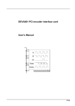
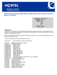
This document shows example code for using µC/OS-II on a Freescale MC9S08 processor. To
demonstrate the MC9S08, we used a P&E DEMOQE evaluation board as shown in Figure 1-1.
We used the Freescale Codewarrior for Microcontrollers IDE version 6.0 to demonstrate this
application. However, other tool-chains could be used.
Figure 1-1, P&E DEMOQE EVB
The application code is downloaded into Flash using a P&E Micro BDM Multilink. While the
application is running, the 4 onboard LEDs sequentially illuminate and blink. µC/Probe may be
used to view various graphs depicting data read from the on-board accelerometer.
To use µC/Probe with the DEMOQE128, download and install the trial version of the program
from the Micriµm website as discussed below in the section 2.05, µC/Probe. After programming
your target with one of the included example projects, connect a RS-232 cable between your PC
and the evaluation board, configure the RS-232 options (also covered below), and start running
the program.
The open data screens should begin to update. Please note that the
communication baud rate for the MC9S08 should be configured to 38,400 baud and not higher.
3
Micriµm
µC/OS-II and µC/Probe on the Freescale MC9S08
1.01
Setting up the Hardware
The following table illustrates the recommended jumper configuration for the DEMOQE EVB.
Jumper Label
J3
J4
J5
J6
J7
J8
J9
J11
J12
J13
J14
J15
J16
J18
J19
J20
J21
Description
Set to USB Power
Set to 3v
User may select
Across RXD and PTB0
Across TXD and PTB1
COM_EN ON
All ON
PTC0, PTC1 both OFF
All ON
0
0
1
PTA7, PTC7, and PTA1 only
Reset_EN, LED_EN both ON
ON
SDL, SDA both ON
PTA0 only
Table 1-1
1.02
Port Specific Details
Two µC/OS-II ports and example projects have been written for the MC9S08 to accommodate
both the banked and non banked memory models. For both ports, the paging option must not be
enabled within the Codewarrior project settings. This application note uses the terms non-banked
and non-paged interchangeably. The terms banked and paged are also used in place of one
another.
Care must be taken to ensure that the correct µC/OS-II, and µC/CPU files are compiled when
running in either non-banked or banked memory model. Files from both ports must not be mixed
together within any project. Separate directories have been created for files belonging to both the
non-paged and paged µC/OS-II and µC/CPU ports. However, other modules such as
µC/Probe, group the port files within the same directory and are distinguished by file name.
Example µC/Probe file names for non-banked and banked assembly port files are as follows:
probe_rs232_nba.s
probe_rs232_ba.s
This example uses the on chip FLL. Once configured, the processor clock is set to 48MHz and
the bus clock to 24MHz. The FLL settings may be changed from within BSP.c. by adjusting
FLL_Init() accordingly. Note: In some cases, oscillator trimming may be desired. In order to
adjust the port for a trimmed oscillator, the target oscillator frequency must be known and set
within BSP.h. This may be accomplished by adjusting the macro BSP_INT_REF_FREQ prior to
compilation. The default value is set to 32768 Hertz.
4
Micriµm
µC/OS-II and µC/Probe on the Freescale MC9S08
Additionally, this example assumes the use of TPM1, channel 0 for the µC/OS-II periodic time
tick interrupt. If TPM1 channel 0 is not available, this you may configure an alternate TPM1
channel by adjusting the macro named OS_TICK_TPM1_CH within BSP.h for channel numbers 0,
1 or 2. The file vectors.c will also require modification. See the section labeled “vectors.c” for more
information.
All ISRs must be written as specified in the section labeled “Creating Interrupt Service Routines”
1.03
Directories and Files
The code and documentation of the port are placed in a directory structure according to
“AN-2002, µC/OS-II Directory Structure”. Files for both the banked and non banked memory
models are provided by Micrium.
µC/OS-II:
\Micrium\Software\uCOS-II\Source
This directory contains the processor independent code for µC/OS-II. The version used
was 2.85.
\Micrium\Software\uCOS-II\Ports\MCS08\Paged\Codewarrior
This directory contains the standard processor specific files for a µC/OS-II port
assuming the Freescale Codewarrior IDE. These files could easily be modified to work
with other tool chains; however, you would place the modified files in a different directory.
Only one processor port, non-paged or paged may be compiled in to a µC/OS-II project
at any given time. Specifically, this directory contains the following files for the banked
memory model:
os_cpu.h
os_cpu_a.s
os_cpu_c.c
µC/Probe:
C:\Micrium\Software\uC-Probe\Target\Communication\Generic\OS\uCOS-II
This directory contains the OS dependent interface for the communication layer of
µC/Probe. If you plan to run µC/Probe with a different RTOS, or without any RTOS,
the following files would have to be adjusted accordingly:
probe_com_os.c
C:\Micrium\Software\uC-Probe\Target\Communication\Generic\RS-232\OS\uCOS-II
This directory contains OS dependent interface code for the RS-232 specific portion of
µC/Probe, specifically the code necessary to generate an optional Rx packet parse
task. If you plan to run µC/Probe with a different RTOS, modifications to the files listed
below will have to be made. If you are not running an RTOS, the following files may be
excluded from the build.
probe_rs232_os.c
5
Micriµm
µC/OS-II and µC/Probe on the Freescale MC9S08
C:\Micrium\Software\uC-Probe\Target\Communication\Generic\RS-232\Ports\Freescale\MC9S08
This directory contains the µC/Probe hardware port files for the MC9S08 processor.
Care must be taken to ensure that the correct assembly file, either probe_rs232_ba.s
(banked assembly) or probe_rs232_nba.s (non banked assembly) is compiled into you
project. Non-banked and banked assembly files must never be mixed within the same
µC/Probe project.
probe_rs232c.c
probe_rs232_ba.s
probe_rs232_nba.s
C:\Micrium\Software\uC-Probe\Target\Communication\Generic\RS-232\Source
This directory contains target independent source code for the µC/Probe RS-232
communication layer. Specifically, this directory contains the following files:
probe_rs232.c
probe_rs232.h
C:\Micrium\Software\uC-Probe\Target\Communication\Generic\Source
This directory contains target independent source code for the
communication layer. Specifically, this directory contains the following files:
µC/Probe
probe_com.c
probe_com.h
C:\Micrium\Software\uC-Probe\Target\Plugins\uCOS-II
This directory contains the target independent source code for µC/Probe. Specifically,
this directory contains the following files:
os_probe.c
os_probe.h
6
Micriµm
µC/OS-II and µC/Probe on the Freescale MC9S08
µC/CPU:
\Micrium\Software\uC-CPU\
This directory contains processor independent files for µC/CPU. µC/CPU contains code
for entering and existing critical sections, as well as macro definitions for the ‘C’
programming datatypes used in most Micrium products. Specifically, this directory
includes:
cpu_def.h
\Micrium\Software\uC-CPU\Ports\MCS08\Paged\Codewarrior
This directory contains processor port files for µC/CPU. µC/CPU contains code for
entering and existing critical sections, as well as macro definitions for the ‘C’
programming datatypes used in most Micrium products. Care must be taken to ensure
that the correct memory model port files for µC/CPU are used when building your
project. Only one port, either non-paged or paged, may be compiled into a given project
at any time. The following directory contains the following files.
cpu.h
cpu_a.s
μC/LIB:
\Micrium\Software\uC-LIB
This directory contains lib_def.h, which provides #defines for useful constants (like
DEF_TRUE and DEF_DISABLED) and macros.
\Micrium\Software\uC-LIB\Doc
This directory contains the documentation for μC/LIB.
Application Code:
\Micrium\Software\EvalBoards\Freescale\MC9S08QE128\DEMOQE\Paged\Codewarrior\OS-Probe
This directory contains the Codewarrior project file, OS-Probe.mcp, for the banked version
of AN-1208.
\Micrium\Software\EvalBoards\Freescale\MC9S08QE128\DEMOQE\Paged\Codewarrior
\OS-Probe\Source
This directory contains the sample source code for using µC/OS-II on the MC9S08
micro-controller. This directory contains the following files:
app.c
app_cfg.h
probe_com_cfg.h
derivative.h
includes.h
os_cfg.h
start08.c
vectors.c
7
Micriµm
µC/OS-II and µC/Probe on the Freescale MC9S08
app.c contains the application code, app_cfg.h contains application specific configuration
information such as task priorities and stack sizes, probe_com_cfg.h contains µC/Probe
communication specific configuration, includes.h contains a master include file used by
the application, os_cfg.h is the µC/OS-II configuration file, derivative.h and start08.c are
generated files for MCU compatibility and startup.
vectors.c contains the processor interrupt vector table. This array of Interrupt Service
Routine addresses must be updated whenever a new interrupt is being configured on the
system. Interrupt vectors that are not in use should be plugged with the appropriate
Dummy ISR handler provided.
\Micrium\Software\EvalBoards\Freescale\MC9S08QE128\DEMOQE\Paged\Codewarrior\BSP
This directory contains the Board Support Package for the DEMOQE128 evaluation
board and the MC9S08 MCU. While some of the code in this directory may work on other
MC9S08 derivatives, routines that are hardware dependent such as LED_On() will
require modification depending on the hardware design of your EVB. This directory
contains:
BSP.c
BSP.h
BSP.c contains hardware specific source code for LED services, FLL initialization,
µC/OS-II ticker initialization, and so on.
BSP.h contains prototypes for the BSP initialization and LED service functionality
provided within BSP.c. The OS timer TPM1 channel selection and internal and external
oscillator frequencies are also configured from within this file. You may adjust these
settings by changing the macros OS_TICK_TPM1_CH, BSP_INT_REF_FREQ, and
BSP_EXT_REF_FREQ respectively. BSP_EXT_REF_FREQ has been intentionally defined
to 0 (Hz) since the DEMOQE128 EVB does not have an external oscillator on-board.
\Micrium\Software\EvalBoards\Freescale\MC9S08QE128\DEMOQE\Paged\Codewarrior
\OS-Probe\prm
This directory contains the processor linker file. The user MUST remove all previously
existing vector definitions from within this file in favor of those specified in vectors.c.
Note: The linker file must be changed when porting to a different MC9S08 derivative.
8
Micriµm
µC/OS-II and µC/Probe on the Freescale MC9S08
1.04
Codewarrior IDE
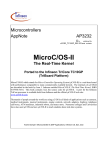
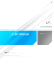
We used the Freescale Codewarrior for Microcontrollers IDE version 6.0 to compile and run the
MC9S08 example. You can of course use µC/OS-II with other tools. Figures 1-3 shows the
project source tree of the banked example project with all of the files visible in the project file
source tree.
Figure 1-3, Codewarrior Source Tree
9
Micriµm
µC/OS-II and µC/Probe on the Freescale MC9S08
2.00
Example Code
As mentioned in the previous section, the test code for this board is found in the following
directories and will be briefly described:
\Micrium\Software\EvalBoards\Freescale\MC9S08QE128\DEMOQE\Paged\Codewarrior\OS-Probe
It should be noted that processor header files and libraries are not included within the AN-1208
code archive since they are supplied by Freescale via the Codewarrior installation.
2.01
Example Code, app.c
app.c demonstrate some of the capabilities of µC/OS-II.
Listing 2-1, main()
void
{
main (void)
CPU_INT08U
(1)
err;
BSP_IntDisAll();
(2)
OSInit();
(3)
OSTaskCreateExt(AppStartTask,
(4)
(void *)0,
(OS_STK *)& AppStartTaskStk[APP_TASK_START_STK_SIZE - 1],
APP_TASK_START_PRIO,
APP_TASK_START_PRIO,
(OS_STK *)&AppStartTaskStk[0],
APP_TASK_START_STK_SIZE,
(void *)0,
OS_TASK_OPT_STK_CHK | OS_TASK_OPT_STK_CLR);
#if OS_TASK_NAME_SIZE > 11
OSTaskNameSet(APP_TASK_START_PRIO, "Startup Task", &err);
#endif
OSStart();
(5)
(6)
}
L2-1(1)
As with most C applications, the code starts in main().
L2-1(2)
We start off by calling a BSP function (see bsp.c) that will disable all interrupts. We
do this to ensure that initialization doesn’t get interrupted in case we do a ‘warm
restart’.
L2-1(3)
As with all µC/OS-II applications, you need to call OSInit() before creating any
task or other kernel objects.
10
Micriµm
µC/OS-II and µC/Probe on the Freescale MC9S08
L2-1(4)
We then create at least one task (in this case we used OSTaskCreateExt() to
specify additional information about your task to µC/OS-II). It turns out that µC/OSII creates up to three tasks in OSInit(). As a minimum, µC/OS-II creates an idle
task (OS_TaskIdle() which is internal to µC/OS-II) and OS_TaskStat() (if you
set OS_TASK_STAT_EN to 1 in os_cfg.h). OS_TaskStat() is also an internal task in
µC/OS-II. The Timer task may be optional enabled or disabled from within os_cfg.h.
L2-1(5)
As of V2.6x, you can now name µC/OS-II tasks (and other kernel objects) and be
able to display task names at run-time or, with a debugger. In this case, we name
our first task ‘Start Task’.
L2-1(6)
We finally start µC/OS-II by calling OSStart(). µC/OS-II will then start executing
AppStartTask() since that’s the highest priority task created. OSStart() does
not return.
Listing 2-2, AppStartTask()
static void AppStartTask (void *p_arg)
{
(void)p_arg;
BSP_Init();
(1)
#if OS_TASK_STAT_EN > 0
OSStatInit();
#endif
(2)
#if (uC_PROBE_OS_PLUGIN > 0)
OSProbe_Init();
OSProbe_SetCallback(AppProbeCallback);
OSProbe_SetDelay(50);
#endif
(3)
(4)
(5)
(6)
#if (uC_PROBE_COM_MODULE > 0)
ProbeCom_Init();
ProbeRS232_Init(38400);
ProbeRS232_RxIntEn();
#endif
(7)
(8)
(9)
AppTaskCreate();
(10)
LED_Off(0);
(11)
while (DEF_TRUE) {
for (j = 0; j < 4; j++) {
for (i = 1; i <= 4; i++) {
LED_On(i);
OSTimeDlyHMSM(0, 0, 0, 20);
LED_Off(i);
OSTimeDlyHMSM(0, 0, 0, 20);
}
(12)
(13)
for (i = 3; i >= 2; i--) {
LED_On(i);
OSTimeDlyHMSM(0, 0, 0, 20);
LED_Off(i);
OSTimeDlyHMSM(0, 0, 0, 20);
}
}
for (i = 0; i < 4; i++) {
LED_On(1);
LED_On(2);
LED_On(3);
LED_On(4);
OSTimeDlyHMSM(0, 0, 0, 50);
11
Micriµm
µC/OS-II and µC/Probe on the Freescale MC9S08
LED_Off(1);
LED_Off(2);
LED_Off(3);
LED_Off(4);
OSTimeDlyHMSM(0, 0, 0, 50);
}
}
}
L2-2(1)
BSP_Init() is called to initialize the Board Support Package – the I/Os, the tick
interrupt, and so on. BSP_Init() will be discussed in the next section.
L2-2(2)
OSStatInit() computes how fast the CPU runs when OS_TASK_STAT_EN is set
to 1 in os_cfg.h.
L2-2(3)
If uC_PROBE_OS_PLUGIN is defined in app_cfg.h, then include code to initialize the target
independent portion of µC/Probe.
L2-2(4)
Initialize the target independent portion of µC/Probe.
L2-2(5)
Configure an optional call-back function for µC/Probe. The callback function is called
each time µC/Probe is queried to update variable values.
L2-2(6)
Set the delay in milliseconds that the µC/Probe task should delay before collecting
information about task stacks and so forth. This task will not be necessary in future versions
of µC/Probe.
L2-2(7)
Initialize the hardware independent portion of the µC/Probe communication layer.
L2-2(8)
Initialize the hardware dependent communication channel. The baud rate for µC/Probe
RS-232 communication should not be set higher than 38,400 on the MC9S08.
L2-2(9)
Enable receive interrupts. This function call enables µC/Probe to begin processing requests
from the host.
L2-2(10)
AppTaskCreate() is a user defined function for creating additional µC/OS-II tasks.
This function is not required and additional tasks could have been created directly
within AppStartTask(). This function has been left empty in this example.
L2-2(11)
Shut off all onboard LEDs.
L2-2(12)
As with all task managed by µC/OS-II, the task body must be in the form of an
infinite loop. Tasks managed by µC/OS-II must never be allowed to exit. Instead,
tasks should be deleted using OSTaskDel() when they are no longer desired. This
task performs the LED illumination and scrolling effect used within this application.
L2-2(13)
As µC/OS-II tasks must either enter an infinite loop ‘waiting’ for some event to occur
or terminate itself. In this case, we wait for time to expire as the ‘event’. This is
accomplished by calling OSTimeDlyHMSM().
12
Micriµm
µC/OS-II and µC/Probe on the Freescale MC9S08
2.02
Example Code, app_cfg.h
This file is used to configure:
Additional µC/ module enables, specifically support for µC/LIB and µC/Probe
The µC/OS-II task priorities of each of the tasks in your application
The stack size for each tasks
2.03
Example Code, includes.h
includes.h is a ‘master’ header file that contains #include directives to include other header files.
This is done to make the code cleaner to read and easier to maintain.
2.04
Example Code, os_cfg.h
This file is used to configure µC/OS-II and defines the maximum number of tasks that your
application can have, which services will be enabled (semaphores, mailboxes, queues, etc.), the
size of the idle and statistic task and more. In all, there are about 60 or so #define’s that you
can set in this file. Each entry is commented and additional information about the purpose of
each #define can be found in the µC/OS-II book. os_cfg.h assumes you have µC/OS-II V2.83
or higher but also works with previous versions of µC/OS-II.
13
Micriµm
µC/OS-II and µC/Probe on the Freescale MC9S08
2.05
μC/Probe
µC/Probe is a Microsoft Windows program that displays the content of system variables on
various user definable graphical elements such as simulated mechanical counters, graphs,
on-screen LEDs and so on.
In order for µC/Probe to display information about your application, an ELF file, must be
generated by the user’s compiler. The ELF file contains the names and addresses of all the
global symbols referenced within the users embedded application. Only symbols that have been
allocated memory, e.g. not allocated on the stack, are able to be monitored by µC/Probe. Global
and static variables are examples of variables that may be monitored.
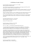
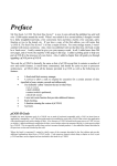
The user places components (such as gauges, labels, and charts) into a Data Screen in a
µC/Probe workspace. Each one of these controls is then assigned to one or more of the
variables from the Symbol Browser. The Symbol Browser lists all symbols referenced from within
the ELF file. Symbols associated with components placed on an open Data Screen will be
updated after the user presses the start button (assuming the user’s PC is connected to the
target and the target is running).
µC/Probe currently interfaces with a target processor via JTAG, RS-232, UDP and USB. A
small section of code resident on the target receives commands from the Windows application
and responds to those commands. The commands ask for a certain number of bytes located at a
certain address, for example, “Send 16 bytes beginning at 0x0040102C”. The Windows
application, upon receiving the response, updates the appropriate component(s) on the data
screen(s) with the new values.
14
Micriµm
µC/OS-II and µC/Probe on the Freescale MC9S08
Start / Stop button.
This button switches
between Design and
Run-Time Views.
During Run-Time View
(when data is
collected), this will
appear as a stop
button (a blue square).
Symbol Browser.
Contains all symbols from the
ELF files added to the
workspace.
Data Screen.
Components are placed onto the data screen and
assigned symbols during Design View. During
Run-Time View, these components are updated
with values of those symbols from the target
Figure 2-1. µC/Probe Windows Program
To use µC/Probe with the example project (or your application), do the following:
1. Download and Install µC/Probe. A trial version of µC/Probe can be downloaded
from the Micriµm website at
http://www.micrium.com/products/probe/probe.html
2. Open µC/Probe. After downloading and installing this program, open the example
µC/Probe workspace for µC/OS-II, named OS-Probe.wsp, which should be located in
the AN-1208 Codewarrior project directory.
You may also open one of the sample workspaces that comes with µC/Probe. The
sample workspaces, located in the µC/Probe target directory, contains generic
workspaces for µC/OS-II, as well as other Micrium software modules.
3. Connect Target to PC. Currently, µC/Probe can use RS-232 to retrieve information
from the target. You should connect a RS-232 cable between your target and computer.
Load Your ELF File. The example projects included with this application note are
already configured to output an ELF file. (If you are using your own project, please refer
15
Micriµm
µC/OS-II and µC/Probe on the Freescale MC9S08
to Appendix A of the µC/Probe user manual for directions for generating an ELF file with
your compiler.) Codewarrior generates an ELF file with a .abs extension. This file is
located in a directory named BIN within the sample project directory.
To load this ELF file, right-click on the symbol browser and choose “Add Symbols”.
Navigate to the file directory, select the file, and choose “OK”.
4. Configure the RS-232 Options. In µC/Probe, choose the “Options” menu item on the
“Tools” menu. A dialog box as shown in Figure 6-2 (left) should appear. Choose the
“RS-232” radio button. Next, select the “RS-232” item in the options tree, and choose the
appropriate COM port and baud rate. The baud rate for the projects accompanying this
application note is 38,400.
5.
6. Start Running. You should now be ready to run µC/Probe. Just press the run button
to see the variables in the open data screens update.
3.00
Board Support Package (BSP)
BSP stands for Board Support Package and provides functions to encapsulate common I/O
access functions in order to make it easier for you to port your application code. In fact, you
should be able to create other applications using the DEMOQE128 evaluation board and reuse
these functions thus saving you a lot of time.
The BSP performs the following functions:
-
Determine the MC9S08s CPU clock and bus frequencies
Configure the LED I/Os for the DEMOQE128 EVB and MC9S08 CPU
Configuration and handling of the µC/OS-II tick timer
The BSP for the DEMOQE128 is found in the follow directory.
\Micrium\Software\EvalBoards\Freescale\MC9S08QE128\DEMOQE\Paged\Codewarrior\BSP
The BSP files are:
BSP.c
BSP.h
3.02
Board Support Package, bsp*.*
We will not be discussing every aspect of the BSP but only cover topics that require special
attention.
Your application code must call BSP_Init() to initialize the BSP. BSP_Init() in turn calls
other essential functions for initializing the MCU to the desired run-time state.
16
Micriµm
µC/OS-II and µC/Probe on the Freescale MC9S08
Listing 3-1, BSP_Init()
void BSP_Init (void)
{
SOPT1
&= ~SOPT1_COPE_MASK;
FLL_Init();
Tmr_TickInit();
LED_Init();
}
(1)
(2)
(3)
(4)
L3-1(1)
Disable the watchdog timer. It is enabled automatically after reset.
L3-1(2)
Initialize the FLL, set ICS_OUT to 50.33MHz using the internal oscillator.
L3-1(3)
Initialize the selected TPM1 channel for use with the µC/OS-II time tick interrupt.
The code for this function is described below.
L3-1(4)
Initialize the general purpose I/O pins used for controlling the onboard LEDs.
Listing 3-2, Tmr_TickInit()
static void Tmr_TickInit (void)
{
CPU_INT32U bus_freq;
bus_freq
bus_freq
OSTickCnts
SCGC1
TPM1SC
TPM1MOD
=
/=
=
|=
=
=
BSP_CPU_ClkFreq();
2;
(1)
(CPU_INT16U)(bus_freq / (8 * OS_TICKS_PER_SEC));
SCGC1_TPM1_MASK;
0;
0;
(3)
(4)
(5)
#if OS_TICK_TPM1_CH == 0
TPM1C0SC
=
TPM1C0SC_MS0A_MASK
TPM1C0SC_CH0IE_MASK;
TPM1C0V
=
TPM1CNT + OSTickCnts;
#endif
|
|
#if OS_TICK_TPM1_CH == 2
TPM1C2SC
=
TPM1C2SC_MS2A_MASK
TPM1C2SC_CH2IE_MASK;
TPM1C2V
=
TPM1CNT + OSTickCnts;
#endif
|=
(6)
(7)
(8)
#if OS_TICK_TPM1_CH == 1
TPM1C1SC
=
TPM1C1SC_MS1A_MASK
TPM1C1SC_CH1IE_MASK;
TPM1C1V
=
TPM1CNT + OSTickCnts;
#endif
TPM1SC
(2)
|
(1 << TPM1SC_CLKSx_BITNUM)
(3 << TPM1SC_PS_BITNUM);
|
(9)
}
L3-2(1)
Get the CPU operating frequency (ICS_OUT) in Hz. This number is divided by 2 in
order to generate the bus frequency. The bus frequency is the reference frequency
for the TPM.
L3-2(2)
Compute the number of timer increments necessary to generate the desired
µC/OS-II time tick period. The ‘8’ represents the TPM prescaler that is configured in
step 10.
17
Micriµm
µC/OS-II and µC/Probe on the Freescale MC9S08
L3-2(3)
Enable the TPM1 module clock.
L3-2(4)
Stop and reset the TPM1 counter.
L3-2(5)
Set the modulus count to 0x00 allowing the timer to freerun from 0x00 to 0xFFFF.
L3-2(6)
If OS_TICK_TPM1_CH in BSP.h is defined as 0, 1, or 2, then configure the
corresponding TPM1 channel for use with the µC/OS-II periodic time tick interrupt.
L3-2(7)
Configure the timer channel for output compare and enable TPM1 channel 0
interrupts.
L3-2(8)
Write the match register with the current value of the TPM1 counter plus the number
of ticks until the next desired match.
L3-2(9)
Configure the TPM1 reference clock source, set the prescaler and enable the timer.
Listing 3-3, Tmr_TickISR_Handler()
void Tmr_TickISR_Handler (void)
{
#if OS_TICK_TPM1_CH == 0
TPM1C0SC
&= ~TPM1C0SC_CH0F_MASK;
TPM1C0V
+=
OSTickCnts;
#endif
(1)
(2)
(3)
#if OS_TICK_TPM1_CH == 1
TPM1C1SC
&= ~TPM1C1SC_CH1F_MASK;
TPM1C1V
+=
OSTickCnts;
#endif
#if OS_TICK_TPM1_CH == 2
TPM1C2SC
&= ~TPM1C2SC_CH2F_MASK;
TPM1C2V
+=
OSTickCnts;
#endif
OSTimeTick();
(4)
}
This function is called from an assembly interrupt service routine which informs µC/OS-II of the
interrupt and calls the ‘C’ code interrupt handler. See os_cpu_a.s and the section labeled “Creating
Interrupt Service Routines” for more information.
L3-3(1)
If OS_TICK_TPM1_CH is configured to 0
L3-3(2)
Clear the interrupt source
L3-3(3)
Adjust the timer channel match register so that a new time tick will occur after
OSTickCnts additional counts.
L3-3(4)
Call OSTimeTick() to inform µC/OS-II of the clock tick.
18
Micriµm
µC/OS-II and µC/Probe on the Freescale MC9S08
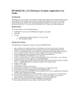
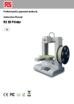
The TPM generates a match interrupt when the up-counter value reaches the value stored within
the timer channel match register. After an interrupt occurs, the match register is incremented to
the next value for which a time tick interrupt is desired. The timer is allowed to free-run and
overflow without error when necessary.
0xFFFF
TPM1CnV
Interrupt on TPM1CHn
0x0000
1 Millisecond with OS_TICKS_PER_SEC
set to 1000. (see os_cfg.h)
Figure 3-1, OS Tick Timer Operation
When the selected TPM issues an interrupt, the processor vectors to the associated TPM module
and channel interrupt service routine. The ISR calls Tmr_TickISR_Handler() as described
above in Listing 3-3.
You should note that ALL of your ISRs should be written in assembly and call an ISR handler
function written in C. The ISR handler should be prototyped as ‘void MyISR_Handler
(void)’. The assembly interrupt service routine is necessary in order to maintain a fully
preemptive RTOS. If the processor is allowed to jump directly to an ISR written in C, then any
task made ready to run as the result of that ISR may have to wait until the interrupted task is
resumed and the scheduler runs. This is non deterministic and is determined by the application
code length. Instead, the ISR handler returns to the assembly interrupt service routine which
immediately calls the scheduler preventing the restoration of a lower priority task context when a
higher priority task should run upon completion of the ISR.
19
Micriµm
µC/OS-II and µC/Probe on the Freescale MC9S08
3.03
Configuring the FLL
The FLL is an on chip peripheral capable of boosting the processor clock and bus frequencies
higher than the frequency provided by either an external or internal oscillator. Before attempting
to reconfigure the FLL from BSP.c you should consult the MC9S08 datasheet and understand the
MCU’s absolute maximum ratings. The absolute maximum ratings must be followed in order to
prevent the possibility of damaging the device.
The MC9S08 has a maximum processor clock of 59.77MHz. The bus clock is always ½ of the
processor clock (ICS_OUT) and must never exceed 25.16 MHz. Therefore, when running
ICS_OUT at the maximum frequency, it becomes necessary to further divide the bus clock to
prevent overclocking of the peripheral bus. Further bus clock division may be performed within
FLL_Init() by setting the BDIV bits greater than 0.
There is no external oscillator on the DEMOQE128, therefore, all clock references are derived
from the MC9S08 internal oscillator and FLL.
The FLL output frequency is computed as follows:
(32768Hz * Pre-selected Multiplier)
Where the pre-selected multiplier has been hard coded within BSP.c, FLL_Init()as 1536 by
the setting of the DCO range to high-range and the DMX32 bit to 0.
Note: BSP_CPU_ClkFreq() returns a 32 bit unsigned integer representation of ICS_OUT, the
processor clock frequency. Dividing this value by 2 will yield the bus clock frequency during runtime. It is recommended that users call this function in order to compute peripheral clock dividers
as opposed to hard coding them. This ensures system integrity should the clock settings require
modification at a later time. The use of this function is demonstrated in Tmr_TickInit().
3.04
vectors.c
vectors.c contains the interrupt vector table for the application. The interrupt vector table is
necessary so that the processor knows the address of the interrupt service routine to jump to
when a specific interrupt occurs. Failure to properly plug the interrupt vector table with the
address of a valid handler may cause the application to crash. If a wrong, but valid, interrupt
handler address is specified for vector number ‘n’ and the interrupt occurs, the interrupt source
will not be cleared the processor will execute the same interrupt service routine indefinitely.
Care should be taken when working with the interrupt vector table.
For convenience, dummy interrupt service routines have been provided for all 32 vectors
excluding reset. When an interrupt vector is not in use, the dummy ISR for that vector should be
set. In the case of a spurious interrupt, the processor will vector to the dummy ISR and loop
indefinitely. Should this occur, you may be able to debug the application and catch the processor
in the dummy interrupt service routine thus identifying the source of the spurious interrupt. The
correct action may then be taken to correct the application to prevent this type of error in the
future.
When plugging the interrupt vector table with a new ISR address, a ‘C’ prototype in the form of:
20
Micriµm
µC/OS-II and µC/Probe on the Freescale MC9S08
extern void near
MyISR(void);
Must be provided at the top of the file. The name of the ISR may then be plugged into the correct
location of the interrupt vector table.
The following vectors are used by µC/OS-II and should not be modified:
•
•
Vector 1: SWI. Used to perform the µC/OS-II context switch.
Vector 4: TPM1 channel 0. This may be adjusted to one of the other TPM1 channel
vectors if desired. The macro named OS_TICK_TPM1_CH in BSP.h will also have to be
adjusted accordingly.
3.05
Creating Interrupt Service Routines
All interrupt service routines must contain a short assembly routine. The address of the assembly
routine is used to plug the interrupt vector table, while the content is designed to notify µC/OS-II
of the interrupt and call the user supplied interrupt handler written in either assembly or ‘C’ code.
The prototype specified at the top of Vectors.c (See section 3.04 above) is the ‘C’ code prototype
for the following assembly interrupt service routine. It is this prototype that allows you to plug the
interrupt vector table with the name (address) of the ISR from ‘C’.
As a reminder, the prototype is written as follows:
extern void near
MyISR(void);
Of course, the name of the ISR would change each time a new ISR is declared since two ISR’s of
the same name cannot exist in the system simultaneously.
The format of an interrupt service routine for the BANKED memory model is as follows:
Listing 3-4, MyISR
NON_BANKED:
section
PPAGE:
equ
xdef
MyISR
(3)
xref
xref
xref
xref
OSIntExit
OSIntNesting
OSTCBCur
MyISR_Handler
(4)
(5)
(6)
(7)
MyISR:
lda
psha
(1)
$0078
(2)
(8)
(9)
(10)
PPAGE
pshh
(11)
lda
add
sta
OSIntNesting
#1
OSIntNesting
(12)
(13)
(14)
cmpa
bne
#$01
MyISR1
(15)
(16)
tsx
(17)
21
Micriµm
µC/OS-II and µC/Probe on the Freescale MC9S08
pshx
pshh
ldhx
pula
sta
pula
sta
MyISR1:
call
call
(18)
(19)
(20)
OSTCBCur
(21)
(22)
(23)
(24)
0, x
1, x
MyISR_Handler
OSIntExit
(26)
(26)
pulh
pula
sta
(27)
(28)
(29)
PPAGE
rti
(30)
L3-4(1)
Force the contents of the assembly file, perhaps named: myisr_a.s, into
NON_BANKED memory. This is critical since the processor only has a 16 bit address
bus. Vectors that are accidentally placed into banked memory will have a 24 bit
address (8 bit page number + 16 bit address) and will overflow the slot in the
interrupt vector table. The interrupt handler written in ‘C’ may be placed in banked
memory.
L3-4(2)
A label for the PPAGE register memory address is defined. This label is used in place
of hard coding the PPAGE register address multiple times within the source code.
L3-4(3)
XDEF is a Codewarrior assembly directive for prototyping assembly routines thereby
making them visible from C files such as vectors.c. This directive is not necessarily
portable to other assemblers.
L3-4(4)
(4), (5), (6), and (7) are external references to variables and or functions defined in
‘C’. These variables are referenced from the context of the assembly ISR and must
therefore be declared external such that they are visible to the assembler and ISR
file. This directive is not necessarily portable to other assemblers.
L3-4(8)
MyISR is the name of the interrupt service routine and must match the name
specified in L3-4(3). This ISR name is also external from within vectors.c.
L3-4(8)
Store the H register on the stack of the task that was interrupted. This register is not
automatically stored and restored by the processor interrupt mechanism and must be
pushed and pulled from the stack separately.
L3-4(9)
Load the value of the PPAGE register into the A register.
L3-4(10)
Store the current value of PPAGE on to the stack of the task that was interrupted. This
register is not automatically stored and restored by the processor interrupt
mechanism and must be pushed and pulled from the stack separately. Note:
enabling the PPAGE checkbox within the compiler options in Codewarrior, will cause
the compiler to add code for storing and restoring PPAGE on and off the stack when
an interrupt occurs. Since not all compilers support this feature, the storing and
restoring of PPAGE is manually specified within the port. Enabling this feature will
cause PPAGE to be pushed twice on to the stack and cause the system to fail.
22
Micriµm
µC/OS-II and µC/Probe on the Freescale MC9S08
L3-4(11)
Store the H register on to the stack of the task that was interrupted. This register is
not automatically stored and restored by the processor interrupt mechanism and
must be pushed and pulled from the stack separately.
L3-4(12)
(12), (13), and (14), increment OSIntNesting. This notifies µC/OS-II that at least
one interrupt is in progress and that the scheduler should not schedule any new
tasks to run until all nested interrupts have completed (e.g. OSIntNesting equals
0). It also informs the OS of the interrupt thereby allowing certain µC/OS-II API calls
to return error codes if called from within the context of an ISR.
L3-4(15)
Load a copy of OSIntNesting from memory into a register so a comparison may be
made.
L3-4(16)
Check OSIntNesting to see if its value is 1. If so, then this is the only interrupt in
progress and no nested interrupts are pending completion.
L3-4(17)
(17 – 24), If no interrupts have been nested then the scheduler is free to schedule a
new task when the ISR completes. Therefore the address of the current task TCB
(Task Control Block) is obtained and the current stack pointer is saved to the current
tasks TCB. (OSTCBCur->OSTCBStkPtr = Stack Pointer)
If interrupt have been nested, skip storing the current tasks stack pointer back into its
task control block and jump to MyISR1. Note: the name of the ISR and the labels
used within it must be changed for each new ISR implemented in the system. For
convenience, the number ‘1’ is added to the end of the ISR name in order to create a
unique and convenient label to jump to.
L3-4(25)
Call the user defined ISR handler. Generally the ISR handler is defined and
prototyped in ‘C’. The ISR handler may be located in banked memory.
L3-4(26)
Call OSIntExit(). This informs µC/OS-II about the end of the interrupt. This is
effectively the same as decrementing OSIntNesting and calling the scheduler. A
context switch to a task different than the one that was running before the interrupt
may or may not occur.
L3-4(27)
Restore the H register.
L3-4(28)
Pull the value of PPAGE of the stack of the task that is to be resumed.
L3-4(29)
Restore the PPAGE register.
L3-4(30)
Return to the highest priority task that is ready to run.
The difference between the NON-banked and the banked memory model from an assembly ISR
perspective is the use of JSR vs. the CALL instruction. CALL uses a 24 bit address to jump to and
return from the called function, JSR only uses 16 bit addresses and is only suitable for calling
functions in non-banked memory. Since one can never be sure of a functions linked address
ahead of time, it becomes necessary to substitute JSR for CALL in the banked version of the
µC/OS-II port and associated user interrupt service routines. Likewise, RTS, return from subroutine must be substituted with RTC, return from call. Lastly, the NON-banked port does not
need to save or restore the PPAGE register before or after context switches. This is however
necessary in order to resume execution from within a function that was interrupted from a banked
page in memory.
23
Micriµm
µC/OS-II and µC/Probe on the Freescale MC9S08
For more information, one may compare the non-banked and banked versions of os_cpu_a.s.
Specifically, one should examine Tmr_TickISR which is the µC/OS-II time tick ISR. All
interrupts should be modeled exactly as shown with the exception of the labels used to identify
the sub-routine. Additional examples are available upon request.
3.05
Context Switching on the MC9S08
When a new task is created, a stack frame for that task is initialized from within os_cpu_c.c,
OSTaskStkInit(). The values placed on the initial stack frame represent the desired values
of the processor registers when the task runs for the first time.
The following code shows stack initialization for a banked memory project. Non-banked memory
projects do not need to push a value for PPAGE on to the tasks stack.
Listing 3-5, OSTaskStkInit()
OS_STK *OSTaskStkInit (void (*task)(void *pd), void *p_arg, OS_STK *ptos, INT16U opt)
{
INT16U *wstk;
INT8U *bstk;
wstk
= (INT16U *)ptos;
*--wstk = (INT16U)p_arg;
*--wstk = (INT16U)(task);
bstk
= (INT8U *)wstk;
*--bstk = (INT8U)0x22;
*--bstk = (INT8U)0xAA;
*--bstk = (0x00);
*--bstk = (INT8U)((INT32U)(task) >> 16);
*--bstk = (INT8U)0x11;
return ((OS_STK *)bstk);
(1)
(2)
(3)
(4)
(5)
(6)
(7)
(8)
(9)
(10)
}
L3-5(1)
Cast a pointer to the top of the stack. The top of the new tasks stack is known from
the call to either OSTaskCreate() or OSTaskCreateExt().
L3-5(2)
Push the argument for the task function on to the stack. The argument is an optional
argument passed to either OSTaskCreate() or OSTaskCreateExt() and is often
passed as NULL.
L3-5(3)
Push the tasks (function) address on to the stack. The address is a 16 bit value and
does not include the page number that contains the task.
L3-5(4)
Cast the current top of stack pointer to an 8 bit pointer since the remaining values to
be pushed are only 8 bits each.
L3-5(5)
Push the initial value for the X register on to the stack. We choose 0x22 since it’s the
second register to be restored. This value is easy to identify during debugging.
L3-5(6)
Push the initial value for the A register on to the stack. We choose 0xAA since the
value corresponds to the name of the register. This value is easy to identify during
debugging.
L3-5(7)
Push the initial value for the CCR register on to the stack. Interrupts for the tasks
context are enabled by means of clearing the I-bit for the initial CCR value. Since the
24
Micriµm
µC/OS-II and µC/Probe on the Freescale MC9S08
task has yet to run, we initialize the CCR to 0 to indicate that no condition codes have
been set, and that global interrupts should be enabled when the task is running.
L3-5(8)
Push the PPAGE value of the tasks address on to the stack.
L3-5(9)
Push the initial value for the H register on to the stack. We chose 0x11 since H is the
first register to be restored. This value is easy to identify during debugging.
L3-5(10)
Return a pointer to the new top of stack.
Note: since a task body is in the form of an infinite loop, the return address is never utilized and
Note
remains on the stack along with p_arg indefinitely.
When the scheduler switches task context, the RTI (Return From Interrupt) instruction is used to
restore all of the system registers from the stack pointer provided.
Since the RTI instruction does not restore H or PPAGE, they must be manually restored before
using RTI. Again, the non-banked port does not require the manual saving or restoration of
PPAGE.
After task stack initialization, the new tasks stack looks as follows:
OSTCBHighRdy->OSTCBStkPtr->
Top of Stack
Low Memory
H
PPAGE
CCR
A
X
PC High Byte
PC Low Byte
Return Address
p_arg High Byte
p_arg Low Byte
Stack grows toward low memory
Figure 3-2
25
High Memory
Bottom of Stack
Micriµm
µC/OS-II and µC/Probe on the Freescale MC9S08
When µC/OS-II scheduler determines that a context switch is necessary, it calls a macro named
OS_TASK_SWITCH()located within os_cpu.h. This macro is defined as __asm swi which in turn
causes the scheduler to invoke a software interrupt. vectors.c loads the SWI interrupt vector with
the address of OSCtxSw()which is located within os_cpu_a.s.
Upon entering OSCtxSw(), SWI pushes the majority of the interrupted tasks context on to the
interrupted tasks stack. Notice the absence of the PPAGE and H register as shown in figure 3-3
below. These registers must be manually saved and restored by the µC/OS-II port. For nonbanked projects, the PPAGE is exempt from this requirement.
Stack Pointer Register ->
Top of Stack
Low Memory
CCR
A
X
PC High Byte
PC Low Byte
…
…
Stack grows toward low memory
High Memory
Bottom of Stack
Figure 3-3
Listing 3-6, OSCtxSw()
OSCtxSw:
lda
psha
PPAGE
(1)
pshh
(2)
tsx
pshx
pshh
ldhx
(3)
pula
sta
pula
sta
OSTCBCur
(4)
0, x
1, x
call
OSTaskSwHook
(5)
lda
sta
OSPrioHighRdy
OSPrioCur
(6)
ldhx
sthx
ldhx
txs
OSTCBHighRdy
OSTCBCur
0, x
(7)
pulh
pula
sta
(8)
(9)
PPAGE
rti
L3-6(1)
(10)
Obtain the PPAGE register value associated with the program counter of the
preempted task. Push PPAGE on to the preempted tasks stack.
26
Micriµm
µC/OS-II and µC/Probe on the Freescale MC9S08
L3-6(2)
Push the H register on to the preempted tasks stack. The stack frame for the
preempted task is now complete.
L3-6(3)
The next group of instructions loads the preempted tasks stack pointer into the 16 bit
HX register. The stack pointer is then pushed on to the preempted tasks stack for
temporary storage. A pointer to the preempted tasks TCB is then loaded into HX.
This pointer also points to the storage location for the tasks stack pointer. The tasks
stack pointer is stored in this location each time the task is swapped out in favor of a
higher priority task that is ready to run.
L3-6(4)
The next group of instructions pulls the preempted tasks stack pointer off of the
preempted tasks stack 1 byte at a time. Each byte is stored within the holding place
located within the preempted tasks TCB. Later, when the this preempted task
becomes the highest priority task that is ready to run, the stack pointer will be
recovered from the TCB and used to restore this tasks context.
L3-6(2)
Call the µC/OS-II task switch hook. This function is defined within os_cpu_c.c and
may be used to notify the application of a context switch. In newer example
applications, the task switch hook calls an application defined task switch hook to
avoid modification to files used by the µC/OS-II port. Application hooks may be
enabled by defining OS_APP_HOOKS_EN to 1 within os_cfg.h. Upon doing so, several
functions will need to be defined within the user application to handle the various
hook function made available by µC/OS-II to the user application.
L3-6(6)
Update the current running task priority to reflect the priority of the task that is about
to be swapped in.
L3-6(7)
Update the currently running task TCB pointer to reflect the address of the TCB that
is about to be swapped in; store this value in the HX register. As mentioned in L36(4), the new task to be swapped in stores the value of its last known stack pointer in
the first location of the TCB. Therefore, the address of the current running task
(though it is not yet running) also points to the stack pointer associated with the task
that will run next. The pointer is dereferenced and the stack pointer address is also
stored in HX. Lastly, the stack pointer address is copied into the stack pointer
register.
L3-6(8)
Restore the new tasks H register. Recall, that the H register is not automatically
restored. Before the task may be run, the stack frame must be reduced from that of
figure of 3-2 to that of 3-3.
L3-6(9)
Obtain and restore the new tasks PPAGE register. Recall, that the PPAGE register is
not automatically restored by the RTI (Return from Interrupt) instruction. In fact, for
the non-banked µC/OS-II port, PPAGE must not be restored. Once PPAGE has been
removed from the stack, the new tasks stack looks like that of figure 3-3 and is ready
to be restored automatically by the RTI instruction.
L3-6(10)
Return from interrupt. This instruction automatically pops PC, X, A, and CCR from the
current stack pointed to by the stack pointer register. The new task is now running
from where it left off prior to its last preemption.
27
Micriµm
µC/OS-II and µC/Probe on the Freescale MC9S08
Licensing
If you intend to use μC/OS-II in a commercial product, remember that you need to contact
Micriµm to properly license its use in your product. The use of μC/OS-II in commercial
applications is NOT-FREE. Your honesty is greatly appreciated.
References
MicroC/OS-II, The Real-Time Kernel, 2nd Edition
Jean J. Labrosse
CMP Technical Books, 2002
ISBN 1-5782-0103-9
Contacts
CMP Books, Inc.
6600 Silacci Way
Gilroy, CA 95020 USA
Phone Orders: 1-800-500-6875
or 1-408-848-3854
Fax Orders: 1-408-848-5784
e-mail: [email protected]
WEB: http://www.cmpbooks.com
Micriµm
949 Crestview Circle
Weston, FL 33327
USA
954-217-2036
954-217-2037 (FAX)
e-mail: [email protected]
WEB: www.Micrium.com
Freescale Technology Inc.
2355 West Chandler Blvd.
Chandler, Arizona 85224-6199
USA
480-792-7200
WEB: www.Freescale.com
28