Download E-RAD USER MANUAL
Transcript
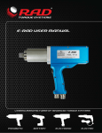
E-RAD USER MANUAL
LEADING MANUFACTURER OF ADVANCED TORQUE SYSTEMS
PNEUMATIC
BATTERY
ELECTRONIC
ELECTRIC
TRANSDUCER
THE INDUSTRY STANDARD...BELIEVE IT!
4
Quick adjust torque settings
Fast and accurate “dial a torque” for maximum versatility and efficiency
4
Soft-start vary speed trigger
Allows operator to safely and quickly set reaction arm before full torque is applied
4
Equal power in forward and reverse
Convenience and cost effective use of same tool for break away and final torque
4
Advanced ultra-durable electric motor design
Extreme duty designed to reduce maintenance cost and increase reliability
4
Advanced gearbox design
PATENTED planetary gear reduction drive system delivering one of the highest
power-to-weight ratios of any controlled bolting system
4
Push-button select torque
Fast and convenient error-free digital single increment torque settings
4
Digital torque console display
Maximum accuracy by seeing the set torque value and the actual delivered torque
value
4
Lightweight and Ergonomic pistol grip design
Advanced low-profile handle to reduce operator fatigue and increase productivity
4
Extremely low noise level only 75db
World’s quietest extreme torque gun, ideal for sensitive environments and
standards
Torque Range
200-6000 ft. lbs.
4
LED Green (Pass) or Red (Fail) indicator lights
Unmistakable visual signal indicates status of torque procedure for maximum
accuracy and speed
BATTERY SERIES
(B-RAD)
4
Quick adjust torque settings
Fast and accurate “dial a torque” for maximum versatility and efficiency
4
Soft-start vary speed trigger
Allows operator to safely and quickly set reaction arm before full torque is applied
4
Equal power in forward and reverse
Convenience and cost effective use of same tool for break away and final torque
4
Imagine the freedom – no air lines, no power cords!
The lightweight design of the B-SERIES makes them ideal for any application,
especially where compressed air and electricity are not readily available.
4
Advanced gearbox design
PATENTED planetary gear reduction drive system delivering one of the highest
power-to-weight ratios of any controlled bolting system
4
PATENTED planetary gear reduction
Delivers one of the highest power-to-weight ratios of any pneumatic controlled
bolting system
4
Smooth continuous flow of controlled torque
Eliminates destructive hammering
4
Lightweight ergonomic pistol grip design
Reduces operator strain and injury; resulting in increased productivity
4
Unmatched reliability and quality
Delivered by one of the most advanced engineered gear boxes on the market
ELECTRIC SERIES
(V-RAD)
Torque Range
100-2300 ft. lbs.
ELECTRONIC SERIES
(E-RAD)
Torque Range
100-1300 ft. lbs.
PNEUMATIC SERIES
Torque Range
50-8500 ft. lbs.
www.radtorque.com
E-RAD 2.5 USER MANUAL
TABLE OF CONTENTS
TABLE OF CONTENTS ..................................................................... 1
MANUAL REVISION HISTORY ........................................................ 3
IMPORTANT SAFETY NOTICE ......................................................... 4
1.0 General Information ................................................................ 5
1.1 System Components ................................................................... 5
1.2 Specifications ............................................................................. 5
1.2.1 Torque Ranges .......................................................................................... 5
1.2.2 Electrical Specifications .............................................................................. 6
1.2.3 Environmental Specifications ...................................................................... 6
2.0 Power Requirements ............................................................... 6
2.1 AC Mains Power.......................................................................... 6
2.2 Earth Grounding Safety ............................................................... 7
2.3 Ground Fault Current Interrupt (GFCI).......................................... 7
2.4 Extension Cords.......................................................................... 7
2.5 Power Cycling............................................................................. 7
3.0 Tool System Assembly ............................................................. 7
3.1 Tool Handle Description .............................................................. 7
3.2 Controller Description.................................................................. 8
3.3 Connecting the Tool Handle, the Controller and the Power ............. 9
4.0 Touch Display Interface ........................................................... 9
4.1 Main Screen ............................................................................. 10
4.2 User Access Levels.................................................................... 10
4.2.1 Unlocking Access Levels ........................................................................... 11
4.2.2 Returning to the Locked Level................................................................... 12
4.3 Functions ................................................................................. 13
4.3.1 Select a Preset ........................................................................................ 13
4.3.2 Setup/Change Data Log File ..................................................................... 14
4.3.3 View a Data Log File ................................................................................ 15
4.3.4 View Tool Information .............................................................................. 16
4.3.5 View Tool Statistics .................................................................................. 16
4.3.6 View Diagnostics ..................................................................................... 17
4.3.7 Change the Set Torque ............................................................................ 18
4.3.8 Change the Set Angle .............................................................................. 18
4.3.9 Modify Presets ......................................................................................... 19
4.3.10 Change the Torque Units ........................................................................ 20
4.3.11 Enable/Disable Angle Mode ..................................................................... 20
4.3.12 Enable/Disable Angle Lock ...................................................................... 21
4.3.13 Enable/Disable Reverse Target ................................................................ 21
4.3.14 Enable/Disable Power-Up Lock ................................................................ 22
4.3.15 Enable/Disable Increment ....................................................................... 22
4.3.16 Enable/Disable Reverse Confirmation ....................................................... 23
4.3.17 Operator Password ................................................................................ 23
4.3.18 Maintenance Cycle Lock.......................................................................... 25
4.3.19 Maintenance Count Threshold ................................................................. 26
4.3.20 Clear Maintenance Statistics .................................................................... 27
4.3.21 Point Calibration .................................................................................... 27
4.3.22 Tool Calibration ..................................................................................... 29
4.3.23 Low Pre-Torque ..................................................................................... 30
4.3.24 Factory Configurations ........................................................................... 33
5.0 General Operating Instructions ............................................. 33
New World Technologies Inc.
V2014.07.04
Page • 1
E-RAD 2.5 USER MANUAL
5.1 Reaction Arm ........................................................................... 33
5.1.1
5.1.2
5.1.3
5.1.4
Installing the Reaction Arm ...................................................................... 33
Reaction Arm Height ................................................................................ 34
Reaction Arm Foot ................................................................................... 35
Reaction Points ....................................................................................... 35
5.2 Torque Only Operation .............................................................. 36
5.3 Angle Only Operation ................................................................ 37
5.4 Torque and Angle Operation ...................................................... 38
5.4.1 Increment Disabled.................................................................................. 38
5.4.2 Increment Enabled .................................................................................. 39
5.5 Reviewing the Last Result.......................................................... 40
6.0 Data Log PC Operations ......................................................... 41
6.1 Software Installation and PC Requirements ................................. 41
6.2 Connecting E-RAD and PC ......................................................... 41
6.3 Setting the Clock ...................................................................... 43
6.4 Downloading all Data Logs ........................................................ 43
6.5 Deleting Data Logs from the E-RAD............................................ 44
6.6 Exporting Data ......................................................................... 44
6.7 Uploading Operator Password File .............................................. 45
7.0 Troubleshooting..................................................................... 46
7.1 Error Messages......................................................................... 46
7.1.1 Blank E-RAD Touch Display ...................................................................... 47
7.1.2 Fixed in Initialization Screen ..................................................................... 47
7.1.3 FB Not Ready/Analog Sensor .................................................................... 47
7.1.4 Feedback Loss ......................................................................................... 47
7.1.5 Overspeed .............................................................................................. 47
7.1.6 Position Error .......................................................................................... 47
7.1.7 Position Limit Exceeded ............................................................................ 47
7.1.8 Motor Stuck ............................................................................................ 47
7.1.9 Peak Current Exceeded ............................................................................ 47
7.1.10 Inhibited ............................................................................................... 47
7.1.11 Motor Cannot Start ................................................................................ 47
7.1.12 DB Inconsistent ..................................................................................... 48
7.1.13 Under Voltage ....................................................................................... 48
7.1.14 Over Voltage ......................................................................................... 48
7.1.15 Short Circuit .......................................................................................... 48
7.1.16 Over Temp ............................................................................................ 48
7.1.17 “Internal Error” or “Program Error” .......................................................... 48
7.1.18 “Watchdog Tripped” ............................................................................... 48
7.2 Solutions.................................................................................. 48
7.2.1
7.2.2
7.2.3
7.2.4
7.2.5
7.2.6
Power-Cycle ............................................................................................ 48
AC Power Cable ....................................................................................... 49
Tool Handle Motor and Feedback Cables .................................................... 49
AC Mains Power Supply ............................................................................ 49
Needs Cooling ......................................................................................... 49
Forward/Reverse Switch ........................................................................... 49
8.0 Contact Us ............................................................................. 50
New World Technologies Inc.
V2014.07.04
Page • 2
E-RAD 2.5 USER MANUAL
MANUAL REVISION HISTORY
Revision 2011.10.26: Initial Release for Firmware ERAD.25.0103
Revision 2012.03.02:
-
Updated Section 6.0 – Data Log PC Operations
-
Removed Reverse Torque Option until next firmware release
-
Removed Serial Printer Option – Hardware no longer supported.
Revision 2012.04.26:
-
ERAD25.0111 Firmware Release
-
Updated PC Software Download Instructions
Revision 2012.11.20:
-
ERAD25.0115 Firmware Release
Revision 2013.08.09:
-
ERAD25.0117 Firmware Release
Revision 2014.07.04:
-
New World Technologies Inc.
V2014.07.04
ERAD25.0117 User Manual
Page • 3
E-RAD 2.5 USER MANUAL
IMPORTANT SAFETY NOTICE
RAD TOOLS ARE SAFE AND RELIABLE. NOT FOLLOWING PRECAUTIONS AND
INSTRUCTIONS OUTLINED HERE CAN RESULT IN INJURY TO THE TOOL,
OPERATOR AND FELLOW WORKERS.
NEW WORLD TECHNOLOGIES INCORPRATED IS NOT RESPONSIBLE FOR ANY
SUCH INJURY.
The intended use of the E-RAD Tool System is for commercial and industrial bolting
applications.
Do not operate the E-RAD Tool System before reading and understanding this user manual
and noting the Safety Notices displayed on the E-RAD Tool System and throughout this
manual.
Only qualified personnel with training in the safe operation of torque tooling and the E-RAD
Tool System should attempt the installation, operation and diagnosis of the E-RAD Tool
System. The E-RAD Tool System is connected to high voltage power and consists of external
rotating parts. Improper training and use can cause serious or fatal injury.
Do not disassemble or attempt to repair the E-RAD Tool System; doing so will void warranty.
If breakdown, malfunction, or damage occurs and the E-RAD Tool System fails to operate
correctly, contact New World Technologies Inc. Technical Support (refer to Section 8.0 –
Contact Us).
The E-RAD Tool System should only be used if environmental storage and operation
specifications have been met. Refer to Section 1.2.3 – Environmental Specifications.
Electrical Shock can cause serious or fatal injury. Do not apply power to the E-RAD Tool
System without verifying the Earth Ground. Ensure the E-RAD Controller and Tool Handle are
properly Earth Grounded before turning on the Power Switch. Do not touch any power devices
or electrical connections or remove the E-RAD Controller Top Plate before ensuring the Power
Switch is in the Off Position, the AC Mains Power has been disconnected and no high voltage
is present.
Ensure all AC Mains Power wiring to the E-RAD AC Power Cable comply with all National and
Local Electrical Codes. Improper wiring may result in unsafe conditions for equipment and
personnel.
New World Technologies Inc. does not recommend replacing the supplied AC Power Cable.
If using a different power cable or a power plug adapter, ensure the Earth Ground pin is
present and firmly connected.
While operating the E-RAD Tool System, always wear safety goggles and keep all body parts
clear of moving parts and the reaction arm contact point.
Always support the E-RAD Tool Handle while the E-RAD Tool System is in use. This will
prevent unexpected release in the event of fastener or component failure.
Never exceed the Maximum Torque of the E-RAD Tool System. Failure to comply will result
in void warranty.
The E-RAD Tool System has been calibrated by a qualified Calibration Technician; calibration
must be done by a qualified Calibration Technician. Improper calibration can cause damage
to the tool and joint.
New World Technologies Inc.
V2014.07.04
Page • 4
E-RAD 2.5 USER MANUAL
1.0 General Information
1.1 System Components
The E-RAD Tool System is shipped from New World Technologies Inc. with the following
parts:
-
E-RAD Torque Tool Handle (Figure 1.1-1)
E-RAD Touch Controller (Weatherproof (Figure 1.1-2) or Steel Case)
AC Power Cable (Figure 1.1-3)
Tool Handle Motor and Feedback Cables
Standard Reaction Arm (Figure 1.1-4)
Serial Communication Cable (USB A to B) – used for data retrieval
Calibration Certificate
User Manual
Figure 1.1-1: E-RAD Tool Handle
1.2 Specifications
Figure 1.1-2: E-RAD Touch Controller
Figure 1.1-3: AC Power Cable
Figure 1.1-4: Standard Reaction Arm
Note: Some distributors may ship additional parts along with the E-RAD Tool System.
1.2.1 Torque Ranges
The following table outlines the torque ranges, in Foot-Pounds and Newton-Meters, of each
E-RAD Tool System:
E-RAD 700
E-RAD 1200
E-RAD 2000
E-RAD 2500 COMP
E-RAD 3000
E-RAD 4000
E-RAD 6000
Table 1.2.1-1: Torque Ranges
New World Technologies Inc.
V2014.07.04
100
200
250
250
500
800
1500
– 700 FtLb
– 1200 FtLb
– 2000 FtLb
– 2500 FtLb
– 3000 FtLb
– 4000 FtLb
– 6000 FtLb
Or
Or
Or
Or
Or
Or
Or
135 – 950 Nm
270 – 1600 Nm
340 – 2700 Nm
340 – 3400 Nm
675 – 4050 Nm
1080 – 5400 Nm
2030 – 8100 Nm
Page • 5
E-RAD 2.5 USER MANUAL
1.2.2 Electrical Specifications
Ensure that all Electrical Specifications are followed when utilizing the E-RAD Tool System.
Nominal Input Voltage
Minimum Input Voltage
Maximum Input Voltage
Nominal Tool Voltage
Minimum Tool Voltage
Maximum Tool Voltage
Nominal Input Current
Peak Tool Input Current
Table 1.2.2-1: Electrical Specifications
Intermittent Operations
Units
VAC
VAC
VAC
VDC
VDC
120V Model
230V Model
120
208 - 240
80% of Calibration Voltage
110% of Calibration Voltage
160
328
80% of Calibration Voltage
VDC
110% of Calibration Voltage
ARMS
ARMS
5
15
10 sec / 5 sec
5
15
ON / OFF
E-RAD 120VAC TOOLS ARE CSA/UL CERTIFIED
E-RAD 230VAC TOOLS ARE CE CERTIFIED
1.2.3 Environmental Specifications
CAUTION!
Only operate the E-RAD Tool System if the following environmental storage and operation
specifications have been met.
Ambient Operating Temperate Range
Minimum
Maximum
Storage Temperature Range
Humidity
Table 1.2.3-1: Environmental Specifications
All Models
deg C
deg F
-20
-4
40
104
-25 to 70
-13 to 158
10% to 90% non-condensing
2.0 Power Requirements
The installer of this equipment is responsible for complying with National Electrical Code
(NEC) or equivalent and Federal and Local Guidelines and Application Codes that govern
protection, Earth Grounding, disconnects and other current protection for electrical
equipment for use in outdoor or indoor applications.
The following sections outline the E-RAD power requirements.
2.1 AC Mains Power
DANGER!
Electrical Shock can cause serious or fatal injury. Do not apply power to the E-RAD Tool
System without verifying the Earth Ground. Ensure the E-RAD Controller and Tool Handle are
properly Earth Grounded before turning on the Power Switch. Do not touch any power device
or electrical connection or remove the E-RAD Controller Top Plate before ensuring the Power
Switch is in the Off Position, the AC Mains Power has been disconnected and no high voltage
is present. New World Technologies Inc. does not recommend replacing the supplied AC
Power Cable. If using a different power cable or a power plug adapter, ensure the Earth
Ground pin is present and firmly connected.
WARNING!
Ensure all AC Mains wiring to the E-RAD AC Power Cable comply with all National and Local
Electrical Codes. Improper wiring may result in unsafe conditions for equipment and
personnel.
The E-RAD Controller requires model specific single phase 120VAC or 230VAC.
The single phase line must be electrically symmetrical with respect to Earth Ground. The
branch circuit must be a dedicated 15A to ensure proper tool operation and to avoid circuit
loading and nuisance trips.
Note: The E-RAD Controller is internally fused for self-protection. Contact New World Technologies Inc.
Technical Support for assistance if a blown fuse is suspected.
New World Technologies Inc.
V2014.07.04
Page • 6
E-RAD 2.5 USER MANUAL
2.2 Earth Grounding Safety
Important!
Earth Grounding is the primary electrical shock protection and is mandatory!
The E-RAD is assembled with a dedicated earth ground connection to the Tool Handle and
Controller via the AC Mains Power Connection.
It is the operator’s responsibility to adhere and follow, at minimum, an Assured Grounding
Program and all National and Local Electrical Codes.
2.3 Ground Fault Current Interrupt (GFCI)
GFCI's are secondary protection devices which protect against electric shock in case of a
ground wiring fault.
The E-RAD 2.5 Controller is compatible with Class A GFCI.
Note: National and Local Electrical Codes may require use of GFCI. Check National and Local Electrical
Code for compliance.
2.4 Extension Cords
Extension cord quality and condition is important to ensure personal safety and E-RAD
performance. Check National and Local Electrical Codes for compliance.
For extension cords under 30ft, 12AWG is recommended; for extension cords over 30ft,
10AWG is recommended.
Generally 100ft is the maximum recommended length for any extension cord, although some
installations demand longer cords. Longer extension cords will reduce the voltage and speed
of the E-RAD Tool System and may cause nuisance trips at higher torque demand.
2.5 Power Cycling
If AC power has been shut off from the E-RAD, it should not be reapplied for at least one
minute. This allows the input surge protection to perform properly. Power cycling too quickly
can cause nuisance trips and reduce the life-time of the electronics.
3.0 Tool System Assembly
CAUTION!
The E-RAD Controller and Tool Handle are calibrated as a system and are identified by the
same serial number. It is important to always ensure the serial numbers match. If not, the
tool will perform torque or angle operations in-accurately. This can cause equipment and joint
failure due to under-torque or over-torque.
The following sections give a visual and functional description of the Tool Handle and
Controller and instructions for connecting the Tool Handle, the Controller and the Power
and Tool Handle Cables.
3.1 Tool Handle Description
The E-RAD Tool Handle (Figure 3.1-1) is trigger activated with a Forward/Reverse Switch.
On each side of the tool housing is a LED Status Display (Figure 3.1-2) which notifies the
operator when the tool is ready for use, when the bolting cycle has passed or if the bolting
cycle has failed.
1.
2.
3.
4.
5.
New World Technologies Inc.
V2014.07.04
Forward/Reverse Switch – controls direction of rotation.
On/Off Trigger – tool activation.
System Ready – blue LED will illuminate when the tool is ready for use.
Fail – red LED will illuminate when the tool fails to complete the torque cycle.
Pass – green LED will illuminate when the tool completes torque operation.
Page • 7
E-RAD 2.5 USER MANUAL
1
2
Figure 3.1-1: E-RAD Tool Handle
3
4
5
Figure 3.1-2: LED Status Display
3.2 Controller Description
The E-RAD Controller has a touch screen interface for ease of bolting operation and status,
as well as advanced configuration options and Data Logging. The AC Power and Tool Handle
Connections are located on the right side of the controller housing. Details are shown below
in Figure 3.2-1 and Figure 3.2-2:
1.
2.
3.
4.
5.
6.
Feedback and Motor Power Connectors for the E-RAD Tool Handle.
AC Mains Input Power Connector (120V AC or 230V AC)
Serial Number for E-RAD Tool System (identical to Serial Number on Tool
Handle)
Communication Port
LCD Touch Display
Power Switch
1
2
Figure 3.2-1: Controller Cable Connections
New World Technologies Inc.
V2014.07.04
Page • 8
E-RAD 2.5 USER MANUAL
6
5
4
3
Figure 3.2-2: Controller Top Plate
3.3 Connecting the Tool Handle, the Controller and the Power
DANGER!
Electrical shock can cause serious or fatal injury. Ensure E-RAD Controller and Tool Handle
are properly Earth Grounded before turning on the Power Switch. Do not turn on power to
the Tool or operate the Tool without verifying the Earth Ground.
CAUTION!
Do not disconnect the electrical connectors while the E-RAD power is on. Damage to the
Tool or Controller will occur.
By following the instructions below, the operator will safely connect the E-RAD Tool System.
Once all these steps have been completed, the E-RAD Tool System will be ready to power
on.
1.
8.
Refer to Section 2.0 – Power Requirements, and ensure compliance before
connecting the Tool Handle or AC Power Cable to the Controller.
Ensure the Tool Handle and Controller Serial Numbers are identical.
Connect the Tool Handle Motor and Feedback Cables to the Motor Power and
Feedback Connectors on the right side of the Controller.
Ensure the AC Mains Supply is Earth Grounded.
Ensure the AC Power Cable is in good condition; there are no cuts or breaks in the
cable insulating jacket and the Plug Pins and Earth Ground Pin are present and in
good condition.
Ensure the E-RAD Power Switch is in the Off Position.
Connect the E-RAD AC Power Cable to the AC Mains Input Power Connector on the
right side of the Controller.
Connect the E-RAD AC Power Cable to the AC Mains Supply.
9.
Check that the E-RAD Controller and Tool Handle are properly Earth Grounded.
2.
3.
4.
5.
6.
7.
4.0 Touch Display Interface
CAUTION!
LCD Touch Displays are susceptible to mechanical shock and any force exerted on the module
may result is damage.
CAUTION!
LCD Touch Displays can be damaged by moisture or water and high temperatures. Avoid
such conditions when storing and gently wipe clean or let dry before usage.
New World Technologies Inc.
V2014.07.04
Page • 9
E-RAD 2.5 USER MANUAL
Note: Dirt from fingerprint oil can easily stain the surface of the display. Gently wipe off any stains
with a soft, lint-free cloth.
The E-RAD Controller includes an LCD Touch Display. This simple touch screen interface has
many functions, including Data Logging, Configuration Options and Torque and Angle
Settings. The following sections describe these functions, as well as how to enable and/or
use them.
4.1 Main Screen
The Main Screen is used as the central control point of the E-RAD Tool System. Here the
operator can access: Menu Options, Presets, Torque and Angle Settings, and Data Logs.
Figure 4.1-1 shows the Main Screen and indicated important aspects.
Data Logs Button
Current Date
& Time
Lock/Unlock
Indicator
Set Torque
Button
Set Angle
Button
Presets
Button
Menu Button
Figure 4.1-1: Main Screen
4.2 User Access Levels
Access to the functions on the Touch Display have been constricted to four Access Levels:
the Locked Level, the Basic Level, the Intermediate Level and the Advanced Level. Access to
the last three levels requires a password. Each level has a different password and access to
different functions. Table 4.2-1 outlines the functions accessible to each level.
New World Technologies Inc.
V2014.07.04
Page • 10
E-RAD 2.5 USER MANUAL
Function
Select a Preset
Setup a Data Log
View a Data Log
View Tool Information
View Tool Statistics
View Diagnostics
Modify Presets
Change Set Torque
Change Set Angle
Change Torque Units
Enable/Disable Angle Mode
Enable/Disable Angle Lock
Enable/Disable Reverse Target
Enable/Disable Power-Up Lock
Enable/Disable Increment
Enable/Disable Reverse Confirmation
Operator Password
Maintenance Cycle Lock
Maintenance Count Threshold
Clear Maintenance Statistics
Point Calibration
Tool Calibration
Low Pre-Torque
Factory Configurations
Table 4.2-1: User Access Levels and Functions
Level
Locked
YES
YES
YES
YES
YES
YES
NO
NO
NO
NO
NO
NO
NO
NO
NO
NO
NO
NO
NO
NO
NO
NO
NO
NO
Basic
YES
YES
YES
YES
YES
YES
YES
YES
YES
YES
NO
NO
NO
NO
NO
NO
NO
NO
NO
NO
NO
NO
NO
NO
Intermediate
YES
YES
YES
YES
YES
YES
YES
YES
YES
YES
YES
YES
YES
YES
YES
YES
YES
YES
YES
YES
YES
NO
NO
NO
Advanced
YES
YES
YES
YES
YES
YES
YES
YES
YES
YES
YES
YES
YES
YES
YES
YES
YES
YES
YES
YES
YES
YES
YES
YES
Note: The E-RAD Tool System is shipped from factory in the Basic Level. After configuration, it is
recommended that the Tool be locked for normal bolting operations to avoid inadvertent changes to Tool
Settings and Calibration.
4.2.1 Unlocking Access Levels
To unlock an Access Level:
1.
Press the “Menu” button on the Main Screen.
2.
Select the “Unlock” option from the Main Menu, shown in Figure 4.2.1-1.
Result: A numeric keypad will be displayed as shown in Figure 4.2.1-2.
Figure 4.2.1-1: Main Menu
New World Technologies Inc.
V2014.07.04
Figure 4.2.1-2: Numeric Keypad
3.
Enter the password for the desired Access Level.
4.
Press “ENT” to confirm the password or “CLR” to correct.
Page • 11
E-RAD 2.5 USER MANUAL
Result: If the password is invalid, an “INCORRECT” message will be displayed (Figure 4.2.1-3). If the
password is correct, the display will return to the Main Screen and the desired Access Level will be
unlocked (Figure 4.2.1-4).
Figure 4.2.1-3: Incorrect Password
Message
Figure 4.2.1-4: Main Screen in the Basic,
Intermediate or Advanced Level
Note: There is no longer a Lock Icon in the top
left corner.
Access Level
Passcode
Basic
37232
Intermediate
Contact your RAD Distributer
Advanced
Contact your RAD Distributer
Table 4.2.1-1: Access Levels and Passwords
4.2.2 Returning to the Locked Level
To return to the Locked Access Level:
1.
Press the “Menu” button on the Main Screen.
2.
Select the “Lock” option from the Main Menu, shown in Figure 4.2.2-1.
Result: A numeric keypad will be displayed as shown in Figure 4.2.2-2.
Figure 4.2.2-1: Main Menu
Figure 4.2.2-2: Numeric Keypad
3.
Enter the password: 37232.
4.
Press “ENT” to confirm the password or “CLR” to correct.
Result: If the password is invalid, an “INCORRECT” message will be displayed (Figure 4.2.23). If the password is correct, the display will return to the Main Screen and the Touch Screen
will have returned to the Locked Level (Figure 4.2.2-4).
New World Technologies Inc.
V2014.07.04
Page • 12
E-RAD 2.5 USER MANUAL
Figure 4.2.2-3: Incorrect Password Message
4.3 Functions
Figure 4.2.2-4: Main Screen in the Locked
Level
Note: The Lock Icon is now displayed in the
top left corner.
The following sections describe the functions available on the E-RAD Touch Display Interface.
Refer to Section 4.2 – User Access Levels for more information on the accessibility of these
functions.
Note: When selecting an option from any menu, press the number to the left of the option.
Note: Menus many consist of several screens. To move through the menu, use the left and right arrow
keys at the bottom of the screen.
Note: Menus will look different depending on the Access Level. The figures in this section are from the
Advanced Access Level.
4.3.1 Select a Preset
A Preset is a pre-defined Set Torque and Set Angle value. They allow the operator to quickly
and efficiently change the Set Torque and Set Angle.
To select a Preset:
1.
Press the “Presets” button on the Main Screen.
2.
Select “Load Preset” from the Preset Menu, shown in Figure 4.3.1-1.
3.
Select the desired Preset from the list displayed. Figure 4.3.1-2 shows an example
of the Load Preset Screen.
Figure 4.3.1-1: Preset Menu
New World Technologies Inc.
V2014.07.04
Figure 4.3.1-2: Load Preset Screen
Page • 13
E-RAD 2.5 USER MANUAL
4.3.2 Setup/Change Data Log File
Note: When the E-RAD Tool System is turned on, the Data Log file name will be set to “DEFAULT.LOG”.
If the E-RAD is turned off during a desired Data Set, the Data Log file must be selected again when
turned back on.
This function allows the operator to create and select Data Log files for recording and viewing
different data sets.
To create a new data log file:
1.
Press the Data Logs button (folder icon) located at the top of the Main Screen.
2.
Select “Select Log” from the Data Log Menu, shown in Figure 4.3.2-1.
Result: The Select Log Screen will be displayed and the currently selected Log will be shown
at the top of the screen and highlighted in the list of Data Logs (Figure 4.3.2-2).
3.
Press the “New” button.
Result: An alpha-numeric keypad will be displayed as shown in Figure 4.3.2-3.
Figure 4.3.2-1: Data Log Menu
4.
Figure 4.3.2-2: Select Log Screen
Figure 4.3.2-3: Alpha-Numeric
Keypad
Enter the desired alpha-numeric file name using the displayed keypad.
Note: Press the key numerous times to cycle through the available characters on that key.
The “1” key includes the characters “-” “_” “.”. If the operator pauses for more than one
second, the cursor will move to the next position.
5.
Press “ENT” to accept the file name or “CLR” to correct.
Result: If the Data Log file name already exists, the operator will be prompted to continue on
the existing Log (Press “ENT”) or choose another file name (Press “CLR”). This prompted
window is shown in Figure 4.3.2-4.
Result: The new Data Log file name (or the continued existing one) will be displayed at the
top of the Main Screen as shown in Figure 4.3.2-5.
Figure 4.3.2-4: Data Log Already Exists Prompt
New World Technologies Inc.
V2014.07.04
Figure 4.3.2-5: Main Screen with New Data Log
Displayed
Page • 14
E-RAD 2.5 USER MANUAL
To select a different data log file:
1.
Press the Data Logs button (folder icon) located at the top of the Main Screen.
2.
Select “Select Log” from the Data Log Menu, shown in Figure 4.3.2-6.
Note: To use “DEFAULT.LOG”, select “Use Default” from the Data Log Menu.
Result: The Select Log Screen will be displayed and the currently selected log will be shown
at the top of the screen and highlighted in the List of Data Logs (Figure 4.3.2-7).
Figure 4.3.2-6: Data Log Menu
3.
Figure 4.3.2-7: Select Log Screen
Select a Data Log.
Result: The Data Log will be shown at the top of the screen and highlighted in the List of
Data Logs.
4.
Press the “Exit” button.
Result: The display will return to the Data Log Menu.
5.
Press the “Exit” button to return to the Main Screen.
Result: The Data Log file name will be displayed at the top of the Main Screen as shown in
Figure 4.3.2-8.
Figure 4.3.2-8: Main Screen with New Data Log Displayed
4.3.3 View a Data Log File
This function allows the operator to view the data stored in the currently selected Data Log
file. To select a different Data Log file, refer to Section 4.3.2 –Setup/Change Data Log File.
To view a data log file:
New World Technologies Inc.
V2014.07.04
1.
Press the Data Logs button (folder icon) located at the top of the Main screen.
2.
Select “View Log” from the Data Log Menu, shown in Figure 4.3.3-1.
3.
View individual Cycle Logs using the left and right arrow keys at the bottom of the
screen.
Page • 15
E-RAD 2.5 USER MANUAL
Figure 4.3.3-1: Data Log Menu
Figure 4.3.3-2: View Cycle Logs –
Figure 4.3.3-3: View Cycle Logs –
Passed Cycle
Failed Cycle
Note: The text will be in green if the cycle passed (Figure 4.3.3-2) and in red if the cycle failed
(Figure 4.3.3-3).
4.
Press the “Exit” button to return to the Main Screen.
4.3.4 View Tool Information
This function allows the operator to view the following E-RAD Tool System information:
-
E-RAD Serial Number
Model Number
Factory Calibration Date
Customer Calibration Date (if Factory Calibration modified)
Calibration Voltage
Total Cycles
Maintenance Cycles
Minimum Torque
Maximum Torque
To view the Tool Information:
1.
Press the “Menu” button on the Main Screen.
2.
Select “Tool Info” from the Main Menu, shown in Figure 4.3.4-1.
Result: The Tool Information Screen will be displayed for 20 seconds or until the “Exit” button
is pressed. An example Tool Information Screen is shown in Figure 4.3.4-2.
Figure 4.3.4-1: Main Menu
Figure 4.3.4-2: Tool Information Screen
4.3.5 View Tool Statistics
This function allows the operator to view the Life Statistics, Maintenance Statistics and Error
Log for the E-RAD Tool System.
To view the Tool Statistics:
New World Technologies Inc.
V2014.07.04
Page • 16
E-RAD 2.5 USER MANUAL
1.
Press the “Menu” button on the Main Screen.
2.
Select “Tool Stats” from the Main Menu, shown in Figure 4.3.5-1.
Result: The Tool Statistics Menu will be displayed (Figure 4.3.5-2). From here, the operator
can select “Life Stats”, “Maint Stats” or “Error Log”.
Figure 4.3.5-1: Main Menu
Figure 4.3.5-2: Tool Statistics Menu
“Life Stats” displays all information since the tool was made (Figure 4.3.5-3).
“Maint Stats” displays all information since the last maintenance (Figure 4.3.5-4).
“Error Log” displays the last error and allows the operator to view individual errors using the
left and right keys at the bottom of the screen.
Note: If an error has not occurred, the Error Log will say “No Errors” (Figure 4.3.5-5).
Figure 4.3.5-3: Life Statistics
Screen
Figure 4.3.5-4: Maintenance
Statistics Screen
Figure 4.3.5-5: Error Log Screen
4.3.6 View Diagnostics
This function displays information used when troubleshooting the E-RAD Tool System. This
information includes Line Voltage, Drive Temperature, Motor Current, Motor Position, Peak
Current, Minimum Voltage and Torque, as well as confirmation of the status of the On/Off
Trigger, the Forward/Reverse Switch and each LED in the LED Status Display. Figure 4.3.6-1
shows the Diagnostics Display.
To view the Diagnostics Display:
New World Technologies Inc.
V2014.07.04
1.
Press the “Menu” button on the Main Screen.
2.
Select “Diagnostics” from the Main Menu, shown in Figure 4.3.6-2.
Page • 17
E-RAD 2.5 USER MANUAL
Figure 4.3.6-1: Diagnostics Display
Figure 4.3.6-2: Main Menu
Note: To return to the Main Screen, press the “Exit” button.
4.3.7 Change the Set Torque
This function allows the operator to change the Set Torque. The Set Torque is the torque
value at which the E-RAD will stop the Torque Cycle and the cycle will be considered a pass.
For more information on the Set Torque and Torque Cycle, refer to Section 5.2 – Torque Only
Operation.
To change the Set Torque:
1.
Press the “Set Torque” button on the Main Screen.
Result: A numeric keypad will be displayed as shown in Figure 4.3.7-1.
2.
Enter the new Set Torque.
Note: Refer to Section 1.2.1 – Torque Ranges.
3.
Press “ENT” to confirm the new Set Torque or “CLR” to correct.
Note: If the entered value is less than the Minimum Torque, it will be corrected to the Minimum
Torque. If the entered value is greater than the Maximum Torque, it will be corrected to the
Maximum Torque.
Result: The new Set Torque will be displayed on the Main Screen (Figure 4.3.7-2).
Figure 4.3.7-1: Numeric Keypad
Figure 4.3.7-2: Main Screen with New Set Torque
4.3.8 Change the Set Angle
This function allows the operator to change the Set Angle. The Set Angle is the angle value
at which the E-RAD will stop the Angle Cycle and the cycle will be considered a pass. For
more information on the Set Angle and Angle Cycle, refer to Section 5.3 – Angle Only
Operation.
Note: To change the Set Angle, Angle Mode must be enabled, refer to Section 4.3.11 – Enable/Disable
Angle Mode.
New World Technologies Inc.
V2014.07.04
Page • 18
E-RAD 2.5 USER MANUAL
To change the Set Angle:
1.
Press the “Set Angle” button on the Main Screen.
Result: A numeric keypad will be displayed as shown in Figure 4.3.8-1.
2.
Enter the new Set Angle.
Note: The Set Angle range is 0 degrees and 10 to 360 degrees.
3.
Press “ENT” to confirm the new Set Angle or “CLR” to correct.
Note: If the new Set Angle is less than 10 degrees and not 0 degrees, it will be corrected to
10 degrees. If the new Set Angle is greater than the maximum, the alert “Too High” will be
displayed (Figure 4.3.8-2). Press “CLR” and the value will change to 360 degrees. The operator
can now enter a different Set Angle or press “ENT” to accept 360 degrees.
Result: The new Set Angle will be displayed on the Main Screen as shown in Figure 4.3.8-3.
Figure 4.3.8-1: Numeric Keypad
Figure 4.3.8-2: Too High Alert
Figure 4.3.8-3: Main Screen with
New Set Angle
4.3.9 Modify Presets
This function allows the operator to modify any of the eight Presets. Presets are pre-defined
values of the Set Torque and the Set Angle. For more information on using Presets, refer to
Section 4.3.1 – Select a Preset.
Note: If Angle Mode is disabled, the Presets will only consist of a Set Torque.
To modify a Preset:
1.
Change the Set Torque and Set Angle to the desired values. Refer to Section 4.3.7
– Change the Set Torque and Section 4.3.8 – Change the Set Angle.
2.
Press the “Presets” button on the Main Screen.
3.
Select “Save Preset” from the Presets Menu, shown in Figure 4.3.9-1.
Result: The Load Preset Screen will be displayed, shown in Figure 4.3.9-2.
4.
Select the desired Preset Number.
Note: The Set Torque and Set Angle values previously stored to the selected Preset Number
will be overwritten.
New World Technologies Inc.
V2014.07.04
Page • 19
E-RAD 2.5 USER MANUAL
Figure 4.3.9-1: Preset Menu
Figure 4.3.9-2: Load Preset Screen
4.3.10 Change the Torque Units
This function allows the operator to change the torque units to Foot-Pounds (FtLb), NewtonMeters (Nm) or Kilogram-Force-Meters (KgFm). When the units are changed, the Set Torque
value, Preset Torque values and Calibration Values are automatically converted to the
selected units.
To change the torque units:
1.
Press the “Menu” button on the Main Screen.
2.
Select “Change Units” from the Main Menu, shown in Figure 4.3.10-1.
3.
Select the desired units from the unit options (Figure 4.3.10-2).
Figure 4.3.10-1: Main Menu
Figure 4.3.10-2: Units Menu
4.3.11 Enable/Disable Angle Mode
This function allows the operator to enable or disable the use of Angle Mode. When this
function is enabled, the operator can change the Set Angle, modify and use Set Angle Preset
values and operate in Angle Only and Torque and Angle Modes. Refer to Section 4.3.1 –
Select a Preset, Section 4.3.8 – Change the Set Angle, Section 4.3.9 – Modify Presets, Section
5.3 – Angle Only Operation and Section 5.4 – Torque and Angle Operation.
To enable/disable Angle Mode:
1.
Press the “Menu” button on the Main Screen.
2.
Select “User Config” from the Main Menu, shown in Figure 4.3.11-1.
3.
Select “Angle On” to enable Angle Mode or “Angle Off” to disable Angle Mode.
Note: When “Angle Off” is displayed, Angle Mode is currently enabled (Figure 4.3.11-2).
New World Technologies Inc.
V2014.07.04
Page • 20
E-RAD 2.5 USER MANUAL
Figure 4.3.11-1: Main Menu
Figure 4.3.11-2: User Configuration Menu
4.3.12 Enable/Disable Angle Lock
WARNING!
Injury to the operator and damage to the E-RAD may occur during an Angle Locked Cycle.
Close attention is required during a cycle to prevent such injury and damage. To stop the
Angle Locked Cycle, switch the Forward/Reverse Switch to the Reverse Position.
This function allows the operator to release the On/Off Trigger during an Angle Only Cycle or
a Torque and Angle Cycle. The cycle will continue until it has passed.
To stop the Angle Locked Cycle at any time, switch the Forward/Reverse Switch to the
Reverse Position. This will result in a failed cycle.
To pause the Angle Locked Cycle, press the On/Off Trigger. This will pause the cycle. To
continue the Angle Locked Cycle, press the On/Off Trigger.
To enable/disable the Angle Lock:
1.
Press the “Menu” button on the Main Screen.
2.
Select “User Config” from the Main Menu, shown in Figure 4.3.12-1.
3.
Select “Ang. Lock On” to enable Angle Lock or “Ang. Lock Off” to disable Angle
Lock.
Note: When “Ang. Lock Off” is displayed, the Angle Lock is enabled (Figure 4.3.12-2).
Figure 4.3.12-1: Main Menu
Figure 4.3.12-2: User Configuration Menu
4.3.13 Enable/Disable Reverse Target
When this function is enabled, the operator can enter a Target Torque for the reverse cycle.
The E-RAD Tool System will reverse until the Actual Torque reaches the Target Torque. This
is similar to a regular Torque Cycle, but in the reverse direction.
To enable/disable Reverse Target:
New World Technologies Inc.
V2014.07.04
Page • 21
E-RAD 2.5 USER MANUAL
1.
Press the “Menu” button on the Main Screen.
2.
Select “User Config” from the Main Menu, shown in Figure 4.3.13-1.
3.
Select “REV TARG ON” to enable the Reverse Target or “REV TARG Off” to disable
the Reverse Target.
Note: When “REV TARG OFF” is displayed, the Reverse Target is enabled (Figure 4.3.13-2).
Figure 4.3.13-1: Main Menu
Figure 4.3.13-2: User Configuration Menu
4.3.14 Enable/Disable Power-Up Lock
When this function is enabled, upon power-up, the E-RAD Touch Display will be in the Locked
Access Level, regardless of the previous state.
To enable/disable Power-Up Lock:
4.
Press the “Menu” button on the Main Screen.
5.
Select “User Config” from the Main Menu, shown in Figure 4.3.14-1.
6.
Select “PUP Lock On” to enable the Power-Up Lock or “PUP Lock Off” to disable
the Power-Up Lock.
Note: When “PUP Lock Off” is displayed, the Power-Up Lock is enabled (Figure 4.3.14-2).
Figure 4.3.14-1: Main Menu
Figure 4.3.14-2: User Configuration Menu
4.3.15 Enable/Disable Increment
This function changes the way the Torque and Angle Operation works. Refer to Section 5.4
– Torque and Angle Operation for more information.
To enable/disable Increment:
New World Technologies Inc.
V2014.07.04
1.
Press the “Menu” button on the Main Screen.
2.
Select “User Config” from the Main Menu, shown in Figure 4.3.15-1.
3.
Select “Increment On” to enable Increment or “Increment Off” to disable
Increment.
Page • 22
E-RAD 2.5 USER MANUAL
Note: When “Increment Off” is displayed, Increment is enabled (Figure 4.3.15-2).
Figure 4.3.15-1: Main Menu
Figure 4.3.15-2: User Configuration Menu
4.3.16 Enable/Disable Reverse Confirmation
This function prevents the operator from reversing without acknowledgement. While this
function is enabled, the Touch Display will prompt the operator to confirm the use of the
reverse setting.
To enable/disable Reverse Confirmation:
1.
Press the “Menu” button on the Main Screen.
2.
Select “User Config” from the Main Menu, shown in Figure 4.3.16-1.
3.
Select “RVS CONF ON” to enable Reverse Confirmation or “RVS CONF OFF” to
disable Reverse Confirmation.
Note: When “RVS CONF OFF” is displayed, Reverse Confirmation is enabled, Figure 4.3.162.
Figure 4.3.16-1: Main Menu
Figure 4.3.16-2: User Configuration Menu
4.3.17 Operator Password
While enabled, this function will disable the operation of the E-RAD Tool System until the
operator logs in using one of the passwords in the Operator Password File uploaded to the
E-RAD (refer to Section 6.7 – Uploading Operator Password File). The operator will still have
full access to the Main Menu and all functions accessible from there. The display will not exit
from the Main Menu, preventing the operator from accessing the Presets, Set Torque, Set
Angle and Data Logs and from operating the E-RAD Tool Handle
For instructions on creating an Operator Password File, refer to Section 6.7 – Uploading
Operator Password File.
To enable/disable the Operator Password:
New World Technologies Inc.
V2014.07.04
Page • 23
E-RAD 2.5 USER MANUAL
1.
Press the “Menu” button on the Main Screen.
2.
Select “User Config” from the Main Menu, shown in Figure 4.3.17-1.
3.
Select “OP P/W On” to enable the Operator Password or “OP P/W Off” to disable
the Operator Password.
Note: When “OP P/W Off” is displayed, the Operator Password is enabled (Figure 4.3.17-2).
Figure 4.3.17-1: Main Menu
Figure 4.3.17-2: User Configuration Menu
To login:
Note: When the Operator Password function is enabled, the display will return to the Main
Menu Screen and the “Login” option will be displayed.
1.
Select “Login” from the Main Menu, shown in Figure 4.3.17-3.
Note: An alpha-numeric keypad will be displayed (Figure 4.3.17-4).
Figure 4.3.17-3: Main Menu
2.
Figure 4.3.17-4: Alpha-Numeric Keypad
Enter an Operator Password.
Note: If an Operator Password File has not been uploaded to the E-RAD, any password can
be used to login.
3.
Press “ENT” to confirm or “CLR” to correct.
Result: The display will return to the Main Menu and the “Logout” option will be displayed
(Figure 4.3.17-5).
To logout:
1.
Press the “Menu” button on the Main Screen.
2.
Select “Logout” from the Main Menu, shown in Figure 4.3.17-6.
Result: The display will return to the Main Menu and the “Login” option will be displayed
(Figure 4.3.17-7).
New World Technologies Inc.
V2014.07.04
Page • 24
E-RAD 2.5 USER MANUAL
Figure 4.3.17-5: Main Menu with
Logout Option
Figure 4.3.17-6: Main Menu
Figure 4.3.17-7: Main Menu with
Login Option
4.3.18 Maintenance Cycle Lock
When enabled, this function will disable the E-RAD after an operator defined number of cycles
is reached. When the operator enables this function, the desired number of Warning Cycles
and Shut-off Cycles must be entered. When the number of cycles defined as Warning Cycles
is reached, the operator will be advised how many cycles remain before the Tool is disabled.
Note: Reverse Cycles are counted as well as Forward Cycles.
To enable/disable the Maintenance Cycle Lock:
1.
Press the “Menu” button on the Main Screen.
2.
Select “User Config” from the Main Menu, shown in Figure 4.3.18-1.
3.
Select “CYC Lock On” to enable the Maintenance Cycle Lock or “CYC Lock Off” to
disable the Maintenance Cycle Lock.
Note: When “CYC Lock Off” is displayed, the Maintenance Cycle Lock is enabled (Figure
4.3.18-2).
Figure 4.3.18-1: Main Menu
Figure 4.3.18-2: User Configuration Menu
To set the Warning Cycles and the Shut-Off Cycles:
Note: To set the Warning Cycles and Shut-Off Cycles, the Maintenance Cycle Lock must be
enabled.
1.
Press the “Menu” button on the Main Screen.
2.
Select “User Config” from the Main Menu, shown in Figure 4.3.18-3.
3.
Select “Cycle Warn” from the User Configuration Menu, shown in Figure 4.3.18-4.
Result: A numeric keypad will be displayed (Figure 4.3.18-5).
New World Technologies Inc.
V2014.07.04
Page • 25
E-RAD 2.5 USER MANUAL
Figure 4.3.18-3: Main Menu
Figure 4.3.18-4: User Configuration
Menu
Figure 4.3.18-5: Numeric Keypad
4.
Enter the desired number of cycles before the operator is advised of the number of
cycles remaining before the E-RAD is disabled for maintenance.
5.
Press “ENT” to confirm the Warning Cycles or “CLR” to correct.
Result: The display will return to the Main Screen.
6.
Press the “Menu” button on the Main Screen.
7.
Select “User Config” from the Main Menu, shown in Figure 4.3.18-6.
8.
Select “Cycle Limit” from the User Configuration Menu, shown in Figure 4.3.18-7.
Result: A numeric keypad will be displayed (Figure 4.3.18-8).
9.
Enter the desired number of cycles before the E-RAD is disabled for maintenance.
10. Press “ENT” to confirm the Shut-Off Cycles or “CLR” to correct.
Result: The display will return to the Main Screen.
Figure 4.3.18-6: Main Menu
Figure 4.3.18-7: User Configuration
Menu
Figure 4.3.18-8: Numeric Keypad
4.3.19 Maintenance Count Threshold
This function restricts the cycles counted toward the Warning Cycles and the Shut-Off Cycles
referred to in Section 4.3.18 – Maintenance Cycle Lock. The operator sets a desired torque
threshold and only cycles with a greater Set Torque than this threshold are counted.
Note: This function is especially useful in tandem with the Maintenance Cycle Lock. Refer to Section
4.3.18 – Maintenance Cycle Lock for more information.
Note: Reverse Cycles with a torque greater than the Threshold Torque will be counted.
To set the Maintenance Count Threshold:
New World Technologies Inc.
V2014.07.04
1.
Press the “Menu” button on the Main Screen.
2.
Select “User Config” from the Main Menu, shown in Figure 4.3.19-1.
Page • 26
E-RAD 2.5 USER MANUAL
3.
Select “Maint PCT TRQ” from the User Configuration Menu, shown in Figure
4.3.19-2.
Result: A numeric keypad will be displayed (Figure 4.3.19-3).
Figure 4.3.19-1: Main Menu
4.
Figure 4.3.19-2: User Configuration
Menu
Figure 4.3.19-3: Numeric Keypad
Enter the desired Minimum Torque Threshold in percent of the E-RAD’s full scale.
Note: The number entered is the desired Minimum Torque Threshold divided by the Maximum
Torque of the E-RAD Tool System multiplied by 100%.
=
minimum torque threshold
× 100%
maximum torque of E RAD
4.3.20 Clear Maintenance Statistics
This function allows the operator to clear the Maintenance Statistics. This is generally done
after maintenance. To view the Maintenance Statistics, refer to Section 4.3.5 – View Tool
Statistics.
To clear Maintenance Statistics:
1.
Press the “Menu” button on the Main Screen.
2.
Select “Tool Stats” from the Main Menu, shown in Figure 4.3.20-1.
3.
Select “Clear Maint” from the Statistics Menu, shown in Figure 4.3.20-2.
4.
Select “Confirm CLR” to confirm the clearing of the Maintenance Statistics or press
the “Exit” button to cancel (Figure 4.3.20-3).
Figure 4.3.20-1: Main Menu
Figure 4.3.20-2: Statistics Menu
Figure 4.3.20-3: Statistics Menu
with Confirm CLR Option
4.3.21 Point Calibration
WARNING!
New World Technologies Inc.
V2014.07.04
Only qualified personnel with training in the safe operation of torque tooling and the E-RAD
Tool System should operate this tool.
Page • 27
E-RAD 2.5 USER MANUAL
This function allows the operator to quickly adjust the Calibration for a specific Set Torque.
Point Calibration is useful in field applications when the torque needs to be verified and
adjusted. This adjustment is only valid when the Point Calibration is enabled and for the
specific Set Torque. If the Set Torque is changed while still in Point Calibration Mode, the
operator will be prompted to recalibrate for the new Set Torque.
Note: Point Calibration does not overwrite the E-RAD Tool Calibration. For information on Tool
Calibration, refer to Section 4.3.22 – Tool Calibration.
To enable/disable Point Calibration:
1.
Press the “Menu” button on the Main Screen.
2.
Select “User Config” from the Main Menu, shown in Figure 4.3.21-1.
3.
Select “Point Cal On” to enable Point Calibration or “Point Cal Off” to disable
Point Calibration (Figure 4.3.21-2).
Result: The display will return to the Main Screen. If Point Calibration is enabled, a target icon
will appear at the top of the Main Screen (Figure 4.3.21-3).
Figure 4.3.21-1: Main Menu
Figure 4.3.21-2: User Configuration
Menu
Figure 4.3.21-3: Main Screen in
Point Calibration Mode
To configure Point Calibration:
Note: A Calibration Stand is needed to perform this procedure.
1.
Ensure Point Calibration is enabled.
2.
Mount E-RAD to the Calibration Stand.
3.
Ensure the Calibration Transducer is set to the same units as the E-RAD Tool System.
4.
Ensure the E-RAD is in Torque Only Mode. Refer to Section 5.2 – Torque Only
Operation.
5.
Press the “Set Torque” button on the Main Screen.
Result: A numeric keypad will be displayed (Figure 4.3.21-4).
6.
Enter the desired Target Torque.
Note: Press “ENT” to confirm torque or “CLR” to correct.
Result: A numeric keypad will be displayed along with a prompt to enter the Measured Torque
1 (Figure 4.3.21-5).
New World Technologies Inc.
V2014.07.04
Page • 28
E-RAD 2.5 USER MANUAL
Figure 4.3.21-4: Numeric Keypad
Figure 4.3.21-5: Numeric Keypad
Figure 4.3.21-6: Numeric Keypad
7.
Operate the E-RAD through one pass cycle.
8.
Enter the torque measured by the Calibration Transducer.
Note: Press “ENT” to confirm torque or “CLR” to correct.
Result: A numeric keypad will be displayed along with a prompt to enter the Measured Torque
2 (Figure 4.3.21-6).
9.
Operate the E-RAD through one pass cycle.
10. Enter the torque measured by the Calibration Transducer.
Note: Press “ENT” to confirm torque or “CLR” to correct.
Result: The Main Screen will be displayed and the Point Calibration Adjustment will be saved.
Result: The torque will be adjusted by the Point Calibration for the Target Torque entered in
Step 5 until a new torque is entered or Point Calibration is disabled.
4.3.22 Tool Calibration
WARNING!
Only qualified personnel with training in the safe operation of torque tooling and the E-RAD
Tool System should operate this tool.
CAUTION!
Do not calibrate at Set Torques that result in exceeding the E-RAD Tool System’s Torque
Range. Severe tool damage will occur.
This function provides access to the Calibration Values for the full Torque Range of the ERAD Tool System. Calibration Values should only be modified by a Qualified Calibration
Technician and with the use of a Calibration Stand.
The Calibration Values represent a relationship between the Actual Output Torque of the ERAD Tool System and the Set Torque. By changing the Calibration Values, the E-RAD is more
accurate and precise.
Note: When the Calibration Values are modified by the operator, the date is stored as the Customer
Calibration Date in the Tool Information. When the Calibration Values are modified by a New World
Technologies Inc. Calibration Technician, the date is stored as the Factory Calibration Date in the Tool
Information. Refer to Section 4.3.4 – View Tool Information.
To calibrate the E-RAD Tool System:
1.
Ensure the E-RAD is in Torque Only Mode. Refer to Section 5.2 – Torque Only
Operation.
2.
Press the “Menu” button on the Main Screen.
3.
Select “User Config” from the Main Menu, shown in Figure 4.3.22-1.
4.
Select “Calibration” from the User Configuration Menu, shown in Figure 4.3.22-2.
Result: A prompt screen will be displayed asking to confirm the Calibration or cancel the
Calibration (Figure 4.3.22-3).
New World Technologies Inc.
V2014.07.04
Page • 29
E-RAD 2.5 USER MANUAL
Figure 4.3.22-1: Main Menu
5.
Figure 4.3.22-2: User Configuration
Menu
Figure 4.3.22-3: Confirm Calibration
Prompt
Press the “ENT” button to enter Calibration.
Result: The 7% Calibration screen will be displayed (Figure 4.3.22-4).
6.
Mount E-RAD to the Calibration Stand.
7.
Ensure the Calibration Transducer is set to the same units as the E-RAD Tool System
8.
Do one Torque Cycle.
9.
Press the “Cal Value” button on the Calibration Screen (Figure 4.3.22-4).
Result: A numeric keypad will be displayed (Figure 4.3.22-5).
10. Enter the torque measured by the Transducer.
11. Press “ENT” to confirm or “CLR” to correct.
Result: The next Calibration Screen will be displayed.
Figure 4.3.22-4: 7% Calibration
Screen
Figure 4.3.22-5: Numeric Keypad
Figure 4.3.22-6: Save Calibration
Prompt
12. Repeat steps 8 to 11 for each torque percentage.
13. Press the “Exit” button.
Result: The operator will be prompted to save before exiting (Figure 4.3.22-6).
14. Press “ENT” to save and exit or “CLR” to not save and exit.
Result: The display will return to the Main Screen.
4.3.23 Low Pre-Torque
This function allows the operator to select from and modify three Low Pre-Torques which are
below the Minimum Torque of the E-RAD Tool System. For more information on Pre-Torque
and when it occurs, refer to Section 5.3 – Angle Only Operation and Section 5.4 – Torque
and Angle Operation.
Note: Angle Mode must be enabled to access and use Low Pre-Torque. Refer to Section 4.3.11 –
Enable/Disable Angle Mode.
New World Technologies Inc.
V2014.07.04
Page • 30
E-RAD 2.5 USER MANUAL
To select a Low Pre-Torque:
1.
Press the “Menu” button on the Main screen.
2.
Select “User Config” from the Main Menu, shown in Figure 4.3.23-1.
3.
Select “Low Pretorque” from the User Configuration Menu, shown in Figure
4.3.23-2.
Figure 4.3.23-1: Main Menu
4.
Figure 4.3.23-2: User Configuration Menu
Select one of the Preset Pre-Torques from the Low Pre-Torque Menu (Figure 4.3.233).
Result: Low Pre-Torque Adjustment Screen will be displayed (Figure 4.3.23-4).
Figure 4.3.23-3: Low Pre-Torque Menu
5.
Figure 4.3.23-4: Low Pre-Torque Adjustment Screen
Press the “Exit” button at the bottom of the screen.
Result: The display will return to the Low Pre-Torque Menu and the selected Low Pre-Torque
will be enabled.
6.
Press the “Exit” button at the bottom of the screen to return to the Main Screen.
To modify a Low Pre-Torque:
New World Technologies Inc.
V2014.07.04
1.
Press the “Menu” button on the Main Screen.
2.
Select “User Config” from the Main Menu, shown in Figure 4.3.23-5.
3.
Select “Low Pretorque” from the User Configuration Menu, Figure 4.3.23-6.
4.
Select the Low Torque from the Low Pre-Torque Menu (Figure 4.3.23-7).
Page • 31
E-RAD 2.5 USER MANUAL
Figure 4.3.22-5: Main Menu
Figure 4.3.23-6: User Configuration
Figure 4.3.23-7: Low Pre-Torque
Menu
Menu
Result: The Low Pre-Torque Adjustment Screen will be displayed. An example of this screen
is shown in Figure 4.3.23-8.
5.
Press the “Torque Value” button on the Low Pre-Torque Adjustment Screen.
Result: A numeric keypad will be displayed (Figure 4.3.23-9).
Figure 4.3.23-8: Low Pre-Torque
Adjustment Screen
Figure 4.3.23-9: Numeric Keypad
6.
Enter the Torque Value.
7.
Press “ENT” to confirm or “CLR” to correct.
8.
Mount E-RAD to the Calibration Stand and ensure the Calibration Transducer is set
to the same units as the E-RAD Tool System
9.
Do one Pre-Torque Cycle.
10. Calculate the Adjustment Value using the torque measured by the Transducer. Use
the following equation:
PreTorque Value
Adjustment Value =
× 1000
Transducer Torque
11. Press the “Adjustment” button on the Low Pre-Torque Adjustment Screen, shown
in Figure 4.3.23-8.
Result: A numeric keypad will be displayed (Figure 4.3.23-10).
New World Technologies Inc.
V2014.07.04
Page • 32
E-RAD 2.5 USER MANUAL
Figure 4.3.23-10: Numeric Keypad
12. Enter the Adjustment Value.
13. Press “ENT” to confirm or “CLR” to correct.
14. Press the “Exit” button at the bottom of the screen.
Result: The display will return to the Low Pre-Torque Menu and the modifications will be
saved.
15. Press the “Exit” button at the bottom of the screen to return to the Main Screen.
4.3.24 Factory Configurations
This function is used to adjust factory settings including Minimum Torque, Maximum Torque,
Angle Mode and Gear Ratio. These settings should only be used under the direction of New
World Technologies Inc. Technical Support.
Note: Contact New World Technologies Inc. Technical Support for more information (refer to Section
8.0 – Contact Us).
5.0 General Operating Instructions
WARNING!
5.1 Reaction Arm
Only qualified personnel with training in the safe operation of torque tooling and the E-RAD
Tool System should operate this tool.
There are three ways to operate the E-RAD Tool System, using Torque Only, Angle Only or
Torque and Angle. Each of these operations, the use of the Reaction Arm and reviewing the
Last Result are discussed in the following sections.
WARNING!
Always keep body parts clear of the Reaction Arm when the E-RAD Tool System is in
use. Serious injury could occur.
CAUTION!
Ensure the Reaction Arm has a solid contact point before operating the E-RAD Tool
System.
5.1.1 Installing the Reaction Arm
Ensure the Reaction Arm and Snap Ring are installed securely to hold the Reaction Arm in
place. Make sure the Reaction Arm is in contact with a solid Reaction Point before you operate
the tool. Keep your body parts clear of the Reaction Arm when the tool is in operation.
When the tool is in operation the Reaction Arm rotates in the opposite direction to the Output
Square Drive and must be allowed to rest squarely against a solid object or surface adjacent
to the bolt to be tightened (Figure 5.1.1-1).
New World Technologies Inc.
V2014.07.04
Page • 33
E-RAD 2.5 USER MANUAL
Figure 5.1.1-1 – Reaction Arm Rotation
CAUTION!
Keep your hand and body parts clear of the Reaction Arm and barrel when the tool is in
operation.
Figure 5.1.1-2: Incorrect Placement of Hand/Body Parts During Operation
5.1.2 Reaction Arm Height
Ensure the height of the socket is even with the height of the Reaction Arm as seen below in
Figure 5.1.2-1. The height of the socket cannot be shorter or higher than the height of the
Reaction Arm as seen below in Figure 5.1.2-2.
CORRECT: The Reaction Arm and socket are even height.
Figure 5.1.2-1: Correct Height
New World Technologies Inc.
V2014.07.04
Page • 34
E-RAD 2.5 USER MANUAL
INCORRECT: The leg of the Reaction Arm is too short on the left side, and too long on the
right side.
Figure 5.1.2-2: Incorrect Height
IMPROPER REACTION WILL VOID WARRANTY AND CAN CAUSE PREMATURE TOOL FAILURE.
5.1.3 Reaction Arm Foot
Ensure the foot of the Reaction Arm aligns with the length of the nut as seen in Figure 5.1.31. The length of the foot cannot be shorter or longer than the nut as seen in Figure 5.1.3-2.
CORRECT: The foot of the Reaction Arm aligns with the length of the nut.
Figure 5.1.3-1: Correct Length
INCORRECT: The foot of the Reaction Arm is too short on the left side, and too long on the
right side.
Figure 5.1.3-2: Incorrect Length
Please contact New World Technologies Inc or your local RAD Authorized Distributor for
custom Reaction Arms.
5.1.4 Reaction Points
Ensure the Reaction Arm reacts off the middle of the foot as seen in Figure 5.1.4-1. Do not
react off the heel of the reaction foot as seen in Figure 5.1.4-2.
New World Technologies Inc.
V2014.07.04
Page • 35
E-RAD 2.5 USER MANUAL
CORRECT: Reaction Arm is reacting off the middle of the Reaction Arm’s foot.
Figure 5.1.4-1: Correct Reaction Point
INCORRECT: Reaction Arm is reacting off the heel of the Reaction Arm. This can cause
premature tool failure.
Figure 5.1.4-2: Incorrect Reaction Point
5.2 Torque Only Operation
This section describes the operation of the E-RAD Torque Only Mode. In Torque Only Mode,
the Torque Cycle has passed when the Actual Torque reaches the Set Torque.
To operate the Torque Only Mode:
1.
Adjust the Set Torque to the desired value by referring to Section 4.3.1 – Select a
Preset, if the E-RAD is in the Locked Level, or Section 4.3.7 – Change the Set Torque,
if the E-RAD is in any other level.
Note: Refer to Section 1.2.1 – Torque Ranges.
2.
Adjust the Set Angle to zero if the Angle Mode is enabled. Refer to Section 4.3.1 –
Select a Preset, if the E-RAD is in the Locked Level, or Section 4.3.8 – Change the
Set Angle, if the E-RAD is in any other level.
3.
Place the E-RAD on the joint system.
4.
Ensure the Forward/Reverse Switch is in the Forward Position.
5.
Ensure the blue “System Ready” LED is illuminated.
6.
Press and hold the Tool Handle On/Off Trigger until the Torque Cycle has passed.
Note: To stop the E-RAD at any time during the Torque Cycle, release the On/Off Trigger.
This will result in a failed Torque Cycle.
Note: After the Torque Cycle has passed or failed, the E-RAD will reverse slightly to unload
the Reaction Arm.
Result: When the Torque Cycle has passed or failed, the Actual Torque (Measured Peak
Torque) will be displayed on the Main Screen. Figure 5.2-1 shows the Main Screen after a
passed Torque Cycle and Figure 5.2-2 shows the Main Screen after a failed Torque Cycle.
New World Technologies Inc.
V2014.07.04
Page • 36
E-RAD 2.5 USER MANUAL
Figure 5.2-1: Passed Torque Cycle
Figure 5.2-2: Failed Torque Cycle
Note: The result will be displayed for ten seconds or until the E-RAD is reversed or a new cycle is
started.
5.3 Angle Only Operation
This section describes the operation of the E-RAD Angle Only Mode. In Angle Only Mode, the
Angle Cycle has passed when the Actual Angle reaches the Set Angle.
To operate in Angle Only Mode, Angle Mode must be enabled by referring to Section 4.3.11
– Enable/Disable Angle Mode.
To operate the Angle Only Mode:
1.
Adjust the Set Torque to zero by referring to Section 4.3.1 – Select a Preset, if the
E-RAD is in the Locked Level, or Section 4.3.7 – Change the Set Torque, if the ERAD is in any other level.
2.
Adjust the Set Angle to the desired value by referring to Section 4.3.1 – Select a
Preset, if the E-RAD is in the Locked Level, or Section 4.3.8 – Change the Set Angle,
if the E-RAD is in any other level.
Note: The Set Angle range is 0 degrees and 10 to 360 degrees.
3.
Place the E-RAD on the joint system.
4.
Ensure the Forward/Reverse Switch is in the Forward Position.
5.
Ensure the blue “System Ready” LED is illuminated.
6.
Press and hold the Tool Handle On/Off Trigger until the Pre-Torque Cycle has
passed.
Result: The result of the Pre-Torque Cycle will be displayed on the Main Screen as shown in
Figure 5.3-1.
Figure 5.3-1: Pre-Torque Cycle
7.
New World Technologies Inc.
V2014.07.04
Press and hold the On/Off Trigger until the Angle Cycle has passed.
Page • 37
E-RAD 2.5 USER MANUAL
Note: To stop the E-RAD at any time during the Angle Cycle, release the Trigger. This will
result in a failed Angle Cycle.
Note: The Angle Cycle will stop if the Actual Torque reaches the Maximum Torque of the ERAD Model.
WARNING!
If the Angle Lock is enabled, the On/Off Trigger does not need to be held during the Angle
Cycle. To stop the Angle Locked Cycle at any time, switch the Forward/Reverse Switch to the
Reverse Position. This will result in a failed Angle Cycle. To pause the cycle, press the On/Off
Trigger. To continue the cycle, press the On/Off Trigger again. Refer to Section 4.3.12 –
Enable/Disable Angle Lock for more information on this function.
Note: After the Angle Cycle has passed or failed, the E-RAD will reverse slightly to unload the Reaction
Arm.
Result: When the Angle Cycle has passed or failed, the Actual Torque and the Actual Angle (total degrees
of rotation) will be displayed on the Main screen. Figure 5.3-2 shows the Main screen after a passed
Angle Cycle and Figure 5.3-3 shows the Main screen after a failed Angle Cycle.
Figure 5.3-2: Passed Angle Cycle
Figure 5.3-3: Failed Angle Cycle
Note: The result will be displayed for ten seconds or until the E-RAD is reversed or a new cycle is
started.
5.4 Torque and Angle Operation
This section describes the operation of the Torque and Angle Mode. The Torque and Angle
Mode works differently if Increment is enabled or disabled. Refer to Section 4.3.14 –
Enable/Disable Increment.
To operate in Torque and Angle Mode, Angle Mode must be enabled by referring to Section
4.3.11 – Enable/Disable Angle Mode.
5.4.1 Increment Disabled
While Increment is disabled, the E-RAD Tool System will do a Torque Cycle to the Set Torque
and then an Angle Cycle to the Set Angle.
To operate the Torque and Angle Mode:
1.
Adjust the Set Torque to the desired value by referring to Section 4.3.1 – Select a
Preset, if the E-RAD is in the Locked Level, or Section 4.3.7 – Change the Set Torque,
if the E-RAD is in any other level.
Note: Refer to Section 1.2.1 – Torque Ranges.
2.
Adjust the Set Angle to the desired value by referring to Section 4.3.1 – Select a
Preset, if the E-RAD is in the Locked Level, or Section 4.3.8 – Change the Set Angle,
if the E-RAD is in any other level.
Note: The Set Angle range is 0 degrees and 10 to 360 degrees.
New World Technologies Inc.
V2014.07.04
3.
Place the E-RAD on the joint system.
4.
Ensure the Forward/Reverse Switch is in the Forward Position.
5.
Ensure the blue “System Ready” LED is illuminated.
Page • 38
E-RAD 2.5 USER MANUAL
6.
Press and hold the On/Off Trigger until the Torque Cycle has passed. This will occur
when the Actual Torque reaches the Set Torque.
Note: To stop the E-RAD at any time during the Torque and Angle Cycle, release the Trigger.
This will result in a failed Torque and Angle Cycle.
7.
Press and hold the On/Off Trigger until the Angle Cycle has passed. This will occur
when the Actual Angle reaches the Set Angle or the Actual Torque reaches the
Maximum Torque of the E-RAD.
Note: The Angle Cycle will stop if the Actual Torque reaches the Maximum Torque of the ERAD Model.
WARNING!
If the Angle Lock is enabled, the On/Off Trigger does not need to be held during the Angle
Cycle. To stop the Angle Locked Cycle at any time, switch the Forward/Reverse Switch to the
Reverse Position. This will result in a failed Angle Cycle. To pause the Cycle, press the On/Off
Trigger. To continue the Cycle, press the On/Off Trigger again. Refer to Section 4.3.12 –
Enable/Disable Angle Lock for more information on this function.
Note: After the Torque and Angle Cycle has passed or failed, the E-RAD will reverse slightly to unload
the Reaction Arm.
Result: When the Torque and Angle Cycle has passed or failed, the Actual Torque (Peak Measured
Torque) and the Actual Angle (Total Degrees of Rotation) will be displayed on the Main Screen. Figure
5.4.1-1 shows the Main Screen after a passed Torque and Angle Cycle and Figure 5.4.1-2 shows the Main
Screen after a failed Torque and Angle Cycle.
Figure 5.4.1-1: Passed Torque and Angle Cycle
Figure 5.4.1-2: Failed Torque and Angle Cycle
Note: The result will be displayed for ten seconds or until the E-RAD is reversed or a new cycle is
started.
5.4.2 Increment Enabled
While Increment is enabled, the E-RAD Tool System will pass Angle Cycles to the Maximum
Angle until the Maximum Torque is reached.
To operate the Torque and Angle Mode:
1.
Adjust the Maximum Torque to the desired value by referring to Section 4.3.1 –
Select a Preset, if the E-RAD is in the Locked Level, or Section 4.3.7 – Change the
Set Torque, if the E-RAD is in any other level.
Note: Refer to Section 1.2.1 – Torque Ranges.
2.
Adjust the Maximum Angle to the desired value by referring to Section 4.3.1 – Select
a Preset, if the E-RAD is in the Locked Level, or Section 4.3.8 – Change the Set
Angle, if the E-RAD is in any other level.
Note: The Set Angle range is 0 degrees and 10 to 360 degrees.
New World Technologies Inc.
V2014.07.04
3.
Place the E-RAD on the joint system.
4.
Ensure the Forward/Reverse Switch is in the Forward Position.
5.
Ensure the blue “System Ready” LED is illuminated.
6.
Press and hold the Tool Handle On/Off Trigger until the Pre-Torque Cycle has
passed.
Page • 39
E-RAD 2.5 USER MANUAL
Result: The result of the Pre-Torque Cycle will be displayed on the Main Screen as shown in
Figure 5.4.2-1.
Figure 5.4.2-1: Pre-Torque Cycle
7.
Press and hold the On/Off Trigger until the Angle Cycle has passed. This will occur
when the Actual Angle reaches the Maximum Angle.
Note: To stop the E-RAD at any time during the Torque and Angle Cycle, release the trigger.
This will result in a failed Torque and Angle Cycle.
8.
WARNING!
Repeat step 7 until the Actual Torque reaches the Maximum Torque. When this
occurs, the Angle Cycle will fail, but the Torque Cycle will pass.
If the Angle Lock is enabled, the On/Off Trigger does not need to be held during the Angle
Cycle. To stop the Angle Locked Cycle at any time, switch the Forward/Reverse Switch to the
Reverse Position. This will result in a failed Angle Cycle. To pause the cycle, press the On/Off
Trigger. To continue the cycle, press the On/Off Trigger again. Refer to Section 4.3.12 –
Enable/Disable Angle Lock, for more information on this function.
Note: After the Torque and Angle Cycle has passed or failed, the E-RAD will reverse slightly to unload
the Reaction Arm.
Result: When the Torque and Angle Cycle has passed or failed, the Actual Torque (Peak Measured
Torque) and the Actual Angle (Total Degrees of Rotation) will be displayed on the Main Screen. Figure
5.4.2-2 shows the Main Screen after a passed Torque and Angle Cycle and Figure 5.4.2-3 shows the Main
Screen after a failed Torque and Angle Cycle.
Figure 5.4.2-2: Passed Torque and Angle Cycle
Figure 5.4.2-3: Failed Torque and Angle Cycle
Note: The result will be displayed for ten seconds or until the E-RAD is reversed or a new cycle is
started.
5.5 Reviewing the Last Result
This function allows the operator to review the results of the last cycle performed.
To review the Last Result:
New World Technologies Inc.
V2014.07.04
Page • 40
E-RAD 2.5 USER MANUAL
1.
Select the “Last Result” text displayed above the Set Torque on the Main Screen
(Figure 5.5-1). This text will appear when the display returns to the Main Screen
after displaying the results of a cycle.
Figure 5.5-1: Last Result Displayed
Note: The Last Result will be displayed for ten seconds or until the E-RAD is reversed or a new cycle is
started.
6.0 Data Log PC Operations
The E-RAD Data Logger allows the operator to connect the E-RAD Touch Controller to a
personal computer (PC) and perform the following actions:
-
Setting the Clock on the E-RAD Tool System (refer to 6.3)
Downloading all Data Logs from the E-RAD Tool System (refer to 6.4)
Deleting Data Logs from the E-RAD Tool System (refer to 6.5)
Exporting Data to another program (refer to 6.6)
Note: The E-RAD Data Logger Program does not work on all operating systems; refer to Section 6.1
for more information.
6.1 Software Installation and PC Requirements
The Smart Socket PC Software can be downloaded from www.eradtorque.com, click on “ERAD Software Download” found on the bottom right of the home page.
After
the
download
is
complete,
follow
the
installation
instructions
in
the
INSTALL_README.txt located in the download package.
The E-RAD Touch Data Logger Software is compatible with Window XP, Vista, and Windows
7 operating systems.
The PC must have a free USB port to be used with the Serial Communications Cable (USB A
to B) provided.
Note: If a physical copy is needed, request a CD copy from your Authorized RAD Distributor or New
World Technologies Inc.
6.2 Connecting E-RAD and PC
To connect the E-RAD Tool System to a PC for Data Log access:
1.
Connect the Serial Communication Cable from the available PC USB Port to the
Communication Port on the E-RAD Controller.
Note: When the Serial Communication Cable is connected to the Communication Port on the
E-RAD Controller, the E-RAD will restart. This is normal, but to prevent it, connect the cable
before turning the E-RAD on.
On the E-RAD Touch Display:
2.
3.
Press the “Menu” button on the Main Screen.
Select “PC Transfer” from the Main Menu, shown in Figure 6.2-1.
Result: The PC Transfer Screen will be displayed (Figure 6.2-2).
New World Technologies Inc.
V2014.07.04
Page • 41
E-RAD 2.5 USER MANUAL
Figure 6.2-1: Main Menu
Figure 6.2-2: PC Transfer Screen
On the PC:
4.
Open the Data Logger Software (Figure 6.2-3).
Figure 6.2-3: Data Logger Main Screen
Note: If the E-RAD is not in PC Transfer Mode, a prompt window will appear (Figure 6.2-4). Ensure the
E-RAD is in PC Transfer Mode and press “OK”.
Figure 6.2-4: PC Mode Prompt Window
New World Technologies Inc.
V2014.07.04
5.
Select the “Options” drop down menu.
6.
Select “Com Port” from the Options Menu (Figure 6.2-5).
Page • 42
E-RAD 2.5 USER MANUAL
Figure 6.2-5: Com Port Selection from Options Menu
7.
Select the correct Com Port for the Serial Communication Cable.
6.3 Setting the Clock
Once the E-RAD Touch Display is in PC Transfer Mode and the Data Logger Software is
running (refer to Section 6.2 – Connecting E-RAD and PC), the E-RAD Data Logger Software
can be used to set the time and date on the Main Screen of the E-RAD Touch Display.
To set the time and date:
1.
Select the “Options” drop down menu.
2.
Select “Set RTC” from the Options drop down menu (Figure 6.3-1).
Figure 6.2-1: Set RTC from Options Menu
Result: The time and date on the E-RAD Main Screen will be updated to the time and date on the PC.
6.4 Downloading all Data Logs
Once the E-RAD Touch Display is in PC Transfer Mode and the Data Logger Software is
running (refer to Section 6.2 – Connecting E-RAD and PC), the operator can download all the
Data Logs from the E-RAD Touch Display to the Data Logger Software.
To download all the Data Logs (on the PC):
1.
Press the “Update Logs” button on the Main Screen (Figure 6.4-1).
Figure 6.4-1: “Update Logs” Button
Result: The Data Logger Software will download all the Data Logs from the E-RAD Tool System. Once
the Data Logs have been downloaded to the Data Logger Software, the operator will be prompted to add
descriptions of the E-RAD and the Data Logs. These descriptions are useful in identifying a Data Log.
Note: All Data Logs are stored on a local database which can be accessed to further manipulate the
data.
New World Technologies Inc.
V2014.07.04
Page • 43
E-RAD 2.5 USER MANUAL
6.5 Deleting Data Logs from the E-RAD
By closing a Data Log in the Data Logger Software, the operator is also deleting the Data Log
from the E-RAD Tool System. The Data Log will be saved on the PC and the title of the Data
Log will be modified to indicate the date it was closed.
Note: The E-RAD must be in PC Transfer Mode and the Data Logger Software must be running before
proceeding with the following instructions. Refer to Section 6.2 – Connecting E-RAD and PC.
To delete a Data Log:
1.
Select the Data Log to be closed (Figure 6.5-1).
Figure 6.5-1: Select a Data Log
2.
Select the “Options” drop down menu.
3.
Select “Close Log” from the Options menu (Figure 6.5-2).
Figure 6.5-2: Close Log from Options Menu
Result: The selected Data Log will be closed in the Data Logger Software and deleted from
the E-RAD Tool System.
6.6 Exporting Data
The Data Logger Software allows the operator to export the data contained within a Data Log
to another program, such as Notepad, WordPad, Microsoft Word or Microsoft Excel for further
manipulation.
To export data from a Data Log:
1.
Select the E-RAD Tool from which the Data Log came from (Figure 6.6-1).
EXAMPLE ERAD 1
EXAMPLE ERAD 2
EXAMPLE ERAD 3
Figure 6.6-1: Select an E-RAD
2.
Select the Data Log (Figure 6.6-2).
LOG 1
LOG 2
3.
New World Technologies Inc.
V2014.07.04
Figure 6.6-2: Select a Data Log
LOG 3
Click and drag the mouse over the data to select it and then release the mouse
(Figure 6.6-3).
Page • 44
E-RAD 2.5 USER MANUAL
Figure 6.6-3: Select data from Data Log
4.
Press “Control” + “C” to copy the data.
5.
Open the other program.
Suggestion: Microsoft Excel usually works best for manipulating the data which is already in
a table setup.
6.
Press “Control” + “V” to paste the data into the program.
6.7 Uploading Operator Password File
When using the Operator Password function outlined in Section 4.3.16 – Operator Password,
the operator must load an Operator Password File onto the E-RAD Tool System. When the
Operator Password function is enabled, the data log files will show the operator’s name if
they are included in the Operator Password File.
Note: In this section, an underscore “_” represents a space. When writing this file, use spaces in place
of the underscores used in these instructions. It is important to have the right spacing or the E-RAD will
not be able to read the file.
To create the Operator Password File:
1.
Open Notepad on the PC.
2.
Enter the first line “PASSWORD_ _ _ _OPERATOR’S_NAME”. See Figure 6.7-1 for an
example of this first line.
Note: Do not include the quotation marks.
Note: All the letters must be capitals.
3.
Use the remaining lines to enter passwords and the corresponding operator names.
4.
Enter the first password and operator’s name on the second line. Example:
“12345678_ _ _ _OPERATOR_121212” (Figure 6.7-1).
Note: The password can be eight characters or less and the operator’s name can be 15
characters or less.
Note: The start of the password lines up with the P in the first line and the start of the
operator’s name lines up with the O in the first line. This must be done regardless of the length
of the password. Any line cannot go passed the E at the end of the first line.
Note: The operator’s name column can be left blank.
5.
Enter more passwords and operator’s names if more than one is needed. Example
with a shorter password: “555_ _ _ _ _ _ _ _ _OPERATOR_2” (Figure 6.7-1).
Note: There is no need to finish the line with spaces. Press enter to start the next line.
Figure 6.7-1: Example Operator Password File
6.
New World Technologies Inc.
V2014.07.04
Save this file with an appropriate name and in an appropriate location.
Page • 45
E-RAD 2.5 USER MANUAL
7.
Open Data Logger Software and ensure the E-RAD Tool System is in PC Transfer
Mode. Refer to Section 6.2 – Connecting E-RAD and PC.
8.
Select the “File” drop down menu.
9.
Select “Upload File” from the File drop down menu (Figure 6.7-2).
Figure 6.7-2: Upload Files from File Menu
Result: A File Explorer Window will appear (Figure 6.7-3).
Figure 6.7-3: File Explorer Window
10. Select the Operator Password File created previously.
11. Press the “Open” button.
Result: A progress bar will appear at the bottom of the Data Logger Main Screen. After the
upload is completed, a message will be displayed indicating if the upload was successful or
not.
7.0 Troubleshooting
DANGER!
Electrical Shock can cause serious or fatal injury. Do not remove the E-RAD Controller Top
Plate or attempt any repairs without approval and training. Do not touch any exposed power
devices, electrical connections or cables.
Important!
Disassembling or attempting repair will void warranty.
7.1 Error Messages
In case of an error or problem, the E-RAD Touch Display will display an active error message,
hindering tool operation. This section lists any error messages or problems that may occur
and references the correct solution found in Section 7.2 – Solutions.
Note: If the problem or error persists after following solution instructions, contact New World
Technologies Inc. Technical Support (refer to Section 8.0 – Contact Us).
New World Technologies Inc.
V2014.07.04
Page • 46
E-RAD 2.5 USER MANUAL
7.1.1 Blank E-RAD Touch Display
After turning the E-RAD Tool System on, the Touch Display remains black.
Solution:
1. Ensure E-RAD Power Switch is on.
2. Refer to 7.2.2 – AC Power Cable.
3. Refer to 7.2.4 – AC Mains Power Supply.
7.1.2 Fixed in Initialization Screen
After turning the E-RAD Tool System on, the Touch Display has started up but is fixed in the
Initialization Screen.
Solution: Refer to 7.2.1 – Power-Cycle.
7.1.3 FB Not Ready/Analog Sensor
The E-RAD Controller is not receiving feedback from the Tool Handle.
Solution: Refer to 7.2.3 – Tool Handle Motor and Feedback Cables.
7.1.4 Feedback Loss
The E-RAD Controller has lost the feedback signal from the Tool Handle.
Solution: Refer to 7.2.3 – Tool Handle Motor and Feedback Cables.
7.1.5 Overspeed
The motor is moving faster than the expected during a cycle. This is usually caused by a loss
of feedback from the motor to the servo driver.
Solution: Refer to 7.2.3 – Tool Handle Motor and Feedback Cables.
7.1.6 Position Error
The motor is not in the expected position. This is usually caused by a loss of feedback from
the motor to the servo driver.
Solution: Refer to 7.2.3 – Tool Handle Motor and Feedback Cables.
7.1.7 Position Limit Exceeded
The motor position exceeded the expected motor movement during an Angle Cycle.
Solution: Refer to 7.2.3 – Tool Handle Motor and Feedback Cables.
7.1.8 Motor Stuck
The servo driver is unable to rotate the motor. This is usually caused by a loss of feedback
or power from the motor to the servo driver.
Solution: Refer to 7.2.3 – Tool Handle Motor and Feedback Cables.
7.1.9 Peak Current Exceeded
The E-RAD Controller or Tool Handle current draw has exceeded the maximum limit (15A).
Solution:
1. Refer
2. Refer
3. Refer
4. Refer
to
to
to
to
7.2.3
7.2.2
7.2.4
7.2.1
–
–
–
–
Tool Handle Motor and Feedback Cables.
AC Power Cable.
AC Mains Power Supply.
Power-Cycle.
7.1.10 Inhibited
The servo driver is unable to rotate the motor. This is usually caused by a loss of feedback
or power from the motor to the servo driver.
Solution: Refer to 7.2.1 – Power-Cycle.
7.1.11 Motor Cannot Start
The servo driver is unable to rotate the motor. This is usually caused by a loss of feedback
or power from the motor to the servo driver.
Solution: Refer to 7.2.1 – Power-Cycle.
New World Technologies Inc.
V2014.07.04
Page • 47
E-RAD 2.5 USER MANUAL
7.1.12 DB Inconsistent
An intermittent fault in the AC/DC conversion has resulted in unexpected changes in signal
amplification.
Solution:
1. Refer to 7.2.2 – AC Power Cable.
2. Refer to 7.2.4 – AC Mains Power Supply.
3. Refer to 7.2.1 – Power-Cycle.
7.1.13 Under Voltage
The DC power provided to the motor does not meet the requirements.
Solution:
1. Refer to 7.2.2 – AC Power Cable.
2. Refer to 7.2.4 – AC Mains Power Supply.
3. Refer to 7.2.1 – Power-Cycle.
7.1.14 Over Voltage
The DC power provided to the motor exceeds the limitations.
1.
2.
3.
Refer to 7.2.2 – AC Power Cable.
Refer to 7.2.4 – AC Mains Power Supply.
Refer to 7.2.1 – Power-Cycle.
7.1.15 Short Circuit
Immediately power off the E-RAD and remove from service. Contact New World Technologies
Inc. Technical Support (refer to Section 8.0 – Contact Us).
7.1.16 Over Temp
The E-RAD Controller’s Internal Temperature has exceeded its maximum.
Solution: Refer to 7.2.5 – Needs Cooling
7.1.17 “Internal Error” or “Program Error”
An “Internal Error” could be any of the following messages:
-
Controller Comms – loss of communication between control modules
Comms Lost – loss of communication between control modules
NVRam Lost – corrupt memory in the Rabbit module resulting in loss of data
Unknown Err
Stack Overflow – program crashed
CPU Fatal Exception – Rabbit failure
Solution: Refer to 7.2.1 – Power-Cycle
7.1.18 “Watchdog Tripped”
The AC/DC conversion is not resulting as expected.
Solution:
1. Refer to 7.2.6 – Forward/Reverse Switch
2. Refer to 7.2.1 – Power-Cycle
7.2 Solutions
DANGER!
Electrical Shock can cause serious or fatal injury. Do not remove the E-RAD Controller Top
Plate and make any repairs without approval and training. Do not touch any exposed power
devices, electrical connections or cables.
The following solutions may help solve the errors described in Section 7.1 – Error Messages.
If the error persists after following the given solution instructions, contact New World
Technologies Inc. Technical Support (refer to Section 8.0 – Contact Us).
7.2.1 Power-Cycle
To Power-Cycle the E-RAD Tool System:
1.
2.
New World Technologies Inc.
V2014.07.04
Switch the Power Switch to the Off Position.
Wait two minutes.
Page • 48
E-RAD 2.5 USER MANUAL
3.
Switch the Power Switch to the On Position and re-try.
7.2.2 AC Power Cable
To check the AC Power Cable:
1.
2.
3.
4.
5.
6.
7.
Switch the Power Switch to the Off Position and wait two minutes before
proceeding.
Remove the AC Power Cable from the AC Mains Power and then from the AC
Mains Input Power Connector on the side of the E-RAD Touch Controller.
Check the visual condition of the AC Power Cable and the pins in the AC Mains
Input Power Connector. Ensure there are no cuts or breaks in the cable
insulating jacket and the pins are present and in good condition.
Connect the AC Power Cable to the AC Mains Input Power Connector.
Ensure the connection is locked tight.
Connect the AC Power Cable to the AC Mains Power.
Switch the Power Switch to the On Position and re-try.
7.2.3 Tool Handle Motor and Feedback Cables
To check the Tool Handle Motor and Feedback Cables:
1.
2.
3.
4.
5.
6.
Switch the Power Switch to the Off Position and wait two minutes before
proceeding.
Remove the Tool Handle Motor and Feedback from the Feedback and Motor
Power Connectors on the side of the E-RAD Controller.
Check the visual condition of the Tool Handle Motor and Feedback Cables and
the pins in the Feedback and Motor Power Connectors. Ensure there are no cuts
or breaks in the cable insulating jacket and the pins are present and in good
condition.
Connect the Tool Handle Motor and Feedback Cables to the Feedback and Motor
Power Connectors.
Ensure the connections are locked tight.
Switch the Power Switch to the On Position and re-try.
7.2.4 AC Mains Power Supply
To check the AC Mains Power Supply:
1.
2.
Ensure the AC Mains Power Supply is present and within specifications.
Ensure the AC Mains Power Supply branch is a dedicated 15A with no other
appliances connected.
Note: If an AC Mains Extension Cord is in use, ensure it meets the minimum E-RAD
specifications for length and gage outlined in Section 2.4 – Extension Cords.
7.2.5 Needs Cooling
To cool the E-RAD Tool System:
1.
2.
Ensure the Controller Cooling Fans are functional and the filter covers are not
blocked.
Switch the Power Switch to the Off Position until the temperature of the system is
within specifications.
7.2.6 Forward/Reverse Switch
To reset using the Forward/Reverse Switch:
1.
2.
3.
New World Technologies Inc.
V2014.07.04
Switch the Forward/Reverse Switch to the Reverse Position.
Switch the Forward/Reverse Switch to the Forward Position.
Re-try.
Page • 49
E-RAD 2.5 USER MANUAL
8.0 Contact Us
New World Technologies Inc.
30580 Progressive Way
Abbotsford, BC, V2T 6Z2
Canada
Toll Free: 1-800-983-0044
Fax: 604-852-0269
Email: [email protected]
Web: www.eradtorque.com
New World Technologies Inc. Technical Support: 1-800-983-0044
(Ext. 227)
Email: [email protected]
New World Technologies Inc.
V2014.07.04
Page • 50
E-RAD Limited Warranty
New Tool Warranty
Any new tool branded with the RAD name and purchased from New World Technologies Inc., or through one
of its authorized distributors or agents, is warranted to the original purchaser against defects in materials and
workmanship for a period of one (1) year from the date of original calibration. The electronic control module
is covered for a period of six (6) months from the date of calibration. Under the terms of this warranty, New
World Technologies Inc., at its option and F.O.B. either its factory or an authorized service center, will replace
or repair for the original purchaser, free of charge, any part or parts, found upon examination by New World
Technologies Inc., to be defective in material or workmanship or both. If any product or part is replaced or
repaired under the terms of this warranty, that product or part will carry the remainder of the warranty from the
date of original calibration.
Repaired Tool Warranty
Once a tool is beyond its new tool warranty, New World Technologies Inc., for a period of three (3) months from
the date of repair, will replace or repair for the original purchaser, free of charge, any part or parts, found upon
examination by New World Technologies Inc., to be defective in material or workmanship or both. If any
product or part is replaced or repaired under the terms and conditions of this warranty, that product or part will
carry the remainder of the warranty from the date of original repair.
To qualify for the above mentioned warranties, written notice to New World Technologies Inc. must be given
immediately upon discovery of such defect, at which time New World Technologies Inc. will issue an
authorization to return the tool. The defective item must promptly be returned to New World Technologies Inc.
all freight charges prepaid. When returning a tool, the reaction arm/s being used with the tool must also be
returned.
New World Technologies Inc.:
Telephone: 1 800 983 0044
Email: [email protected]
Exclusions from Warranty
At New World Technologies Inc.'s sole judgment tools or accessories that have been altered, damaged,
misused, abused, badly worn due to excessive utilization, lost, or improperly maintained will NOT be covered
under the terms of this warranty.
Tools returned without the reaction arm(s) will not be covered under the terms of this warranty. Consumable
parts and accessories (such as extensions, reaction blanks/arms) are not covered under this warranty.
Tools that have been relabeled without prior written consent of New World Technologies Inc. will not be covered
under this warranty.
Equipment and accessories not manufactured by New World Technologies Inc. (measuring equipment, etc.)
are warranted only to the extent of the original manufacturer's warranty.
*There is no other express warranty. Implied warranties, including those of merchantability and fitness for a
particular purpose are limited to one year from date of calibration and to the extent permitted by law. Liability
for consequential damages under any and all warranties are excluded to the extent exclusion is permitted by law.
LIGHTER • FASTER • STRONGER
ABOUT NEW WORLD TECHNOLOGIES INC.
New World Technologies is a leading Canadian manufacturer of
pneumatic, battery powered, and electronic pistol grip torque
wrenches. Our advanced products have proven to be successful
all over the world in such industries as oil and gas, petrochemical,
mining, aerospace, and manufacturing. we continue to invest in
and employ the latest technology to achieve the highest level of
innovation, quality, and performance - which has resulted in
multiple patents for our products.
NEW WORLD TECHNOLOGIES INC.
30580 Progressive Way
Abbotsford, BC V2T 6Z2 Canada
T: 604-852-0405
F: 604-852-0269
E: [email protected]
WWW.RADTORQUE.COM


