1
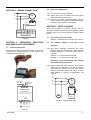
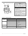
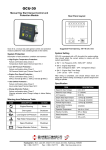
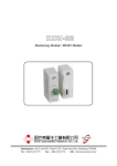
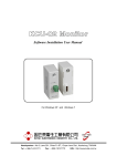
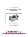
EA45A220
Generator Automatic Voltage Regulator
Operation Manual
Self Excited Automatic Voltage Regulator
45 Amp AVR for Carbon Brush Type Generators
EA45A220HL (Half Wave) / EA45A220FL (Full Wave)
*Parallel version is available for option
Headquarters : No.3, Lane 201, Chien Fu St., Chyan Jenn Dist., Kaohsiung, TAIWAN
Tel : + 886-7-8121771
Fax : + 886-7-8121775
URL : http://www.kutai.com.tw
SECTION 1 : SPECIFICATION
Sensing & power Input
Voltage
170 – 265 Vac, 1 phase 2 wire
Frequency
50 / 60 Hz selectable
Under Frequency Protection (Factory Knee Point Setting)
50 Hz system presets knee point at 45 Hz
60 Hz system presets knee point at 55 Hz
Output (at 220 Vac input)
Voltage
EA45A220HL(Half-wave) Max.90 Vdc
EA45A220FL(Full-wave) Max.180 Vdc
Current
Continuous 45A
Intermittent 60A for 10 sec.
Resistance EA45A220HL Min. 1.4 ohms
EA45A220FL Min. 2.7 ohms
Environment
Operation Temperature
Storage Temperature
Relative Humidity
Vibration
Voltage Regulation
< +/- 1% ( with 4% engine governing )
-40 − +60 ˚C
-40 − +85 ˚C
Max. 95%
3 Gs @ 100 − 2K Hz
Cooling condition
Forced with 120.0 (L) x 120.0 (W) x 38.0 (H) mm fan
Dimensions
330.0 (L) x 189.0 (W) x 180.0 (H) mm
Build Up Voltage
Residual voltage at AVR terminal > 5 Vac @ 25 Hz
External Volts Adjustment
+/- 6%
Weight
EA45A220HL
EA45A220FL
4.5 kgs +/- 2%
5.2 kgs +/- 2%
189.0
169.0
330.0
160.0
180.0
150.0
12
Unit : mm
Outline Drawing
Figure 1
SECTION 2 : ADJUSTMENT
AUTOMATIC
VOLTAGE REGULATOR
POWER LAMP
F
U/F LAMP
S
STAB.
+
VOLT.
HI
LO
U/F
Adjustment
Figure 2
___________________________________________________________________________________________
2
EA45A220
SECTION 3 : WIRING CONNECTION
R
G
~
S
T
Field
4.2
Knee Point Adjustment
4.2.1 Turn the U/F POT fully clockwise.
4.2.2 Adjust VOLT POT to nominal level and speed
down the engine to knee point.
4.2.3 Turn the U/F POT counter-clockwise until the
voltage starts to decrease (U/F lamp illuminates),
re-adjust engine speed to rated speed.
SECTION 5 : FIELD FLASHING
220VAC
F+
POWER
F-
B+
FIELD
B-
BATT.
EA45A220
When the regulator is installed correctly but the
generator is failed to generate power. Besides carbon
brushes were worn out, here are two possible causes
below.
5.1
Solution:Exchange the connection of F+ and F-.
Figure 3
SECTION 4 : FREQUENCY SELECTION
AND KNEE POINT ADJUSTMENT
4.1
The polarity of field is inverse
5.2
The residual voltage is less than 5 Vac,
Solution 1:
Frequency Selection
Detach the controller from enclosure(refer to Figure 4)
and select the system frequency on the back of the
controller(refer to Figure 5).
5.2.1 Shut down generator, disconnect the wiring
between AVR and generator then flash the field.
Flashing duration = 3 seconds. (See wiring in
Figure 6)
Resistor 3 – 5 ohms for full wave AVR
Resistor 5 – 10 ohms for half wave AVR
Warning!! Over field flashing may damage
the field winding of generator.
5.2.2 Restart generator and measure the residual
voltage by AC Voltmeter, if it is still less than 5
Vac, repeat the previous process, after several
times, the residual voltage still cannot be built,
Kutai EB500 is strongly recommended, see
Figure 6.
R
Figure 4
G
~
S
Open : 50Hz
Close : 60Hz
EXT. VR
1K Ohm
T
HZ HZ VR VR
Field
F-
EA45AF PCB
R
(Reverse Side)
J1 close :enable Low frequency protection
open :disable Low frequency protection
V
~
J1
J2
Figure 6
SW
-
+
BATT.
Manual Field Flash
White
Pink
Blue
Magenta
Red
Black
Yellow
1 2 3 4 5 6 7
F+
Figure 5
___________________________________________________________________________________________
EA45A220
3
Solution 2 : Install Kutai automatic flash module
EB500
R
G
~
S
T
WARNING
This Automatic Voltage Regulator is not
equipped with loss-Sensing Protection function /
Over Excitation Protection. An additional
Over-Voltage Protection device for load may be
required to avoid possible damage to the
equipment or severe personal injury or death.
Field
ATTENTION
220VAC
POWER
F+
F-
FIELD
B+
B-
BATT.
EA45A220
Oll pressure or
fuel switch(N.O.)
ACC1
ACC2
F+
F-
B+
B-
EB500
-
+
BATT.
Figure 7
1. AVR installation should only be performed by
a qualified technician.
2. Install AVR inside the generator control panel
to avoid high temperature, moisture, and
location where AVR cannot be easily reached.
3. AVR heat sink may reach a high temperature
(above 60 ˚C) when AVR is powered, do not
touch or ground AVR heat sink.
4. Make sure you have read and understand the
contents of the instruction manual prior to
installation. Incorrect wiring connection may
result in irreversible damage to the product
and other equipments.
SECTION 6 : TROUBLE SHOOTING
SYMPTOM
Voltage does not
build up
POSSIBLE CAUSES
Residual voltage below 5 Vac
SOLUTIONS
Field flash is required
Incorrect wiring
Check wiring diagram for proper connection
Engine under speed
Increase engine speed to above 25 Hz
Carbon brushes were worn out
Replace with new carbon brushes
Voltage set point is not properly adjusted
Adjust VOLT POT clockwise to reach
desired voltage
External voltage adjusted too low
Turn the external VR to reach desired
voltage
Under Frequency Protection is activated
Refer to Section 4 Frequency selection and
knee point adjustment
Over output voltage
Voltage set point is not properly adjusted
Adjust VOLT POT anti-clockwise to reach
rated voltage
Output voltage
unstable (Hunting)
Stability range is not set properly
Refer to Section 2 Adjustment
Field voltage or field resistance is too low
Connect suitable resistor in series to
increase total resistance
Low output voltage
※ Appearance and specifications of products are subject to change for improvement without prior notice.
___________________________________________________________________________________________
4
EA45A220