1
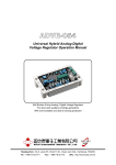
ADVR-08
Universal Hybrid Analog-Digital
Voltage Regulator Operation Manual
An Universal Hybrid Analog/Digital 2 lines sensing 8 Amp AVR with multiple
power input capability such as Full Harmonic (Compound Windings),
Harmonic + Auxiliary Winding, PMG and SHUNT.
Compatible with Leroy Somer* R438, R448, R449 and more.
Use with KUTAI IVT-1260/IVT-2460 add-on module can boost generator
motor starting capacity.
* Use for reference purpose only and do not imply that any part listed above
is the product of the manufacturer.
Headquarters : No.3, Lane 201, Chien Fu St., Chyan Jenn Dist., Kaohsiung, TAIWAN
Tel : + 886-7-8121771
Fax : + 886-7-8121775
URL : http://www.kutai.com.tw
SECTION 1 : SPECIFICATION
Sensing Input (E1, E2)
Voltage
110 − 480 Vac 1 phase
90 − 130 Vac @ 110 Vac
180 − 260 Vac @ 220 Vac
340 − 520 Vac @ 380 Vac
Frequency
50/60 Hz selectable
External Volts Adjustment (VR1, VR2)
+/- 4% 500 ohms 1 watt potentiometer
+/- 8% 1K ohms 1 watt potentiometer
Soft Start Ramp Time
4 sec.
Power Input (X1, X2)
Voltage
40 − 300 Vac, 1 phase
Frequency
50 − 500 Hz
Over Excitation Protection
Inverse-time 170 +/- 5 Vdc @ power input 220 Vac
Unit Power Dissipation
Max.6 watts
Auxiliary Input (Aux1, Aux2)
Voltage
40 − 300 Vac, 1 phase
Frequency
50 − 500 Hz
EMI Suppression
Internal EMI filtering
Output (F+, F-)
Voltage
Max. 63 Vdc @ power input 110 Vac
Max. 125 Vdc @power input 220 Vac
Current
Continuous 8A
Intermittent 12A for 10 sec.
Resistance ≧ 8 ohms @ power input 110 Vac
≧ 16 ohms @ power input 220 Vac
Fuse Spec.
5 x 20mm S505-10A (slow blow type)
Burden in SHUNT & PMG Wiring
880 VA @ power input 110 Vac
1760 VA @ power input 220 Vac
Voltage Regulation
Quadrature Droop Input (S1, S2, S3)
CT 5A (S1-S2) or 1A (S2-S3) > 5VA
Max. +/- 5% @ P.F +/- 0.7
Analogue Input (A1, A2)
Maximum input +/- 5 Vdc
Sensitivity +/- 25% Generator Volts (adjustable)
Input resistance > 2K ohms
Under Frequency Protection (Factory Knee Point Setting)
50 Hz system presets knee point at 47 Hz
60 Hz system presets knee point at 57 Hz
Knee point Frequency Drift:0.1 Hz @ -40 − +70 °C
< +/- 0.5% ( with 4% engine governing )
Typical System Response
AVR response 20 ms
Build Up Voltage
Residual voltage at AVR power input terminal
> 6 Vac @ 25 Hz
Voltage Thermal Drift
0.03% per °C change in AVR ambient
Environment
Operation Temperature
Storage Temperature
Relative Humidity
Vibration
-40 − +70 ˚C
-40 − +85 ˚C
Max. 95%
3 Gs @ 100 − 2K Hz
Dimensions
171.0 (L) x 120.0 (W) x 50.0 (H) mm
Weight
820 g +/- 2%
ATTENTION
Carefully set the AVR sensing voltage from 110 to 480 Vac using DIP Switch SW 4 & 5.
___________________________________________________________________________________________
2
ADVR-08
SECTION 2 : OUTLINE / SIZE / INSTALLATION REFERENCE
Terminal : “Fast-On” terminals 6.35 mm (1/4 inch)
Flag Terminal (“Fast-On” terminal)
Figure 1
Outline Drawing
ATTENTION
Meggers and high-potential test equipment must not be used as it could damage the AVR.
___________________________________________________________________________________________
ADVR-08
3
SECTION 3 : DIP SWITCH PROGRAMMING & ADJUSTMENTS
SW
1
KW
SW
1 2 3 4 5 6
+
-
+
51(61)
HZ
ON
-
2
3
OFF
60Hz
<90
OFF
OFF
ON
50Hz
90~500
OFF
ON
V
SW
>500
ON
ON
4
5
SW
6
-
+
3
10
90~130 180~260 340~520
OFF
ON
OFF
ON
ON
OFF
OFF
O/E ON
ON
O/E OFF
40(50)
HZ
NOTE
For more detail about “ IVT Generator Auxiliary Excitation Booster ” please visit KUTAI website.
___________________________________________________________________________________________
4
ADVR-08
SECTION 4 : WIRING CONNECTIONS
PMG
Exciter field
Armature
C.T
N:5Aor1A
Stator windings
C.T
N:5Aor1A
Stator windings
R
Exciter field
R
Armature
S
T
T
200VAC max 50~500HZ
S
(Harmoni)
AUX. wires
ADVR-08
ADVR-08
S1-S2 N:5A
S2-S3 N:1A
S1-S2 N:5A
S2-S3 N:1A
Figure 2
Figure 3 Three Phase Auxiliary
Winding (Full Harmonic)
Single & Three Phase PMG
Exciter field
Exciter field
Armature
C.T
N:5Aor1A
Stator windings
C.T
N:5Aor1A
Stator windings
Armature
R
R
S
S
T
T
N
Harmoni wires
AUX. wires
ADVR-08
ADVR-08
S1-S2 N:5A
S2-S3 N:1A
S1-S2 N:5A
S2-S3 N:1A
Figure 4
Auxiliary & Harmonic
Figure 5
Self-Excited (SHUNT)
___________________________________________________________________________________________
ADVR-08
5
Exciter field
Armature
C.T
N:5Aor1A
Stator windings
R
S
T
OUT1
OUT2
S1
S2
Droop
%
Time
ON
Test
IVT
ADVR-08
Fuse
Output
Ready
Test
Batt-Volt
OVLD
B
B+
+
S1-S2 N:5A
S2-S3 N:1A
Figure 6
ADVR-08 with IVT-1260 / IVT-2460
ATTENTION
1.
2.
3.
4.
All AC voltage readings are average value only.
Use a remote 500 ohms 1 watt external VR for +/- 4% adjustment range. (keep shorted if not used)
Use a remote 1K ohms 1 watt external VR for +/- 8% adjustment range.
If your PMG is not working you can also power the AVR in shunt using terminals X1 & X2 connected to
the output of the generator as long as it’s less than 300 Vac.
※ Use only the replacement fuses specified in this user manual.
※ Appearance and specifications of products are subject to change for improvement without prior notice.
___________________________________________________________________________________________
6
ADVR-08