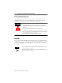
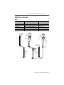
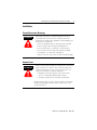
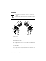
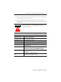
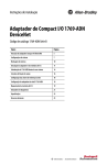
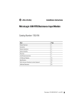
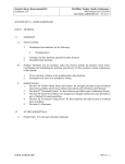
1
Installation Instructions
1769 Compact I/O Communication Bus
Expansion Cables
(Cat. No. 1769-CRR1, -CRR3, -CLL1, -CLL3, -CRL1, -CRL3)
Inside ...
For More Information ..............................
Hazardous Location Considerations ........
Environnements dangereux .....................
Overview ................................................
Cable Types and Lengths ........................
System Configurations ............................
Installation ..............................................
2
3
4
4
5
6
7
Publication 1769-IN014B-EN-P - May 2002
2
1769 Compact I/O Communication Bus Expansion Cables
For More Information
For
Refer to this Document
Pub. No.
Information on how to install and use
your 1769-ADN Adapter
CompactTM I/O 1769-ADN DeviceNet Adapter
Installation Instructions
1769-IN001
Installation guides for 1769 Discrete
Compact I/O module 1769-IA8I
Compact 1769-IA8I Individually Isolated 120V ac
Input Module
1769-IN012
Installation guides for 1769 Discrete
Compact I/O module 1769-IA16
Compact 1769-IA16 120V ac Input Module
Installation Instructions
1769-IN006
Installation guides for 1769 Discrete
Compact I/O module 1769-OW8
Compact 1769-OW8 AC/DC Relay Output Module
Installation Instructions
1769-IN051
Installation guides for 1769 Discrete
Compact I/O module 1769-OW8I
Compact 1769-OW8I Individually Isolated
AC/DC Relay Output Module
1769-IN053
Installation guides for 1769 Discrete
Compact I/O module 1769-IQ16
Compact 1769-IQ16 24V dc Sink/Source Input
Module Installation Instructions
1769-IN007
Installation guides for 1769 Discrete
Compact I/O module 1769-OB16
Compact 1769-OB16 Solid State 24V dc Source
Output Module Installation Instructions
1769-IN054
Installation guides for 1769 Discrete
Compact I/O module 1769-OB16P
Compact 1769-OB16P Solid State 24V dc Source
Output Module Installation Instructions
1769-IN052
Installation guides for 1769 Discrete
Compact I/O module 1769-OA8
Compact 1769-OA8 100 to 240V ac Solid State
Output Module Installation Instructions
1769-IN055
Installation guides for 1769 Discrete
Compact I/O module 1769-OV16
Compact 1769-OV16 Solid State 24V dc Sink Output
Module Installation Instructions
1769-IN056
Installation guides for 1769 Discrete
Compact I/O module 1769-IQ6XOW4
Compact 1769-IQ6XOW4 24V dc Sink/Source Input
1769-IN050
AC/DC Relay Output Module Installation Instructions
Installation guides for 1769 Discrete
Compact I/O module 1769-IM12
Compact 1769-IM12 240V ac Input Module
Installation Instructions
1769-IN011
Installation guides for 1769 Analog
Compact I/O module 1769-IF4
Compact 1769-IF4 Analog Input Module Installation
Instructions
1769-IN048
Installation guides for 1769 Analog
Compact I/O module 1769-OF2
Compact 1769-OF2 Analog Output Module
Installation Instructions
1769-IN049
Installation guides for 1769 Analog
Compact I/O module 1769-IF4XOF2
* For Series B DeviceNet adapters only
Compact 1769-IF4XOF2 Combination Analog Module 1769-IN057
Installation Instructions
Information on how to install and use
your 1769-IF4XOF2 module
Compact 1769-IF4XOF2 8-Bit Low-Resolution Analog 1769-UM008
I/O Combination Module User Manual
Installation guides for 1769 High Speed
Counter module 1769-HSC
* For Series B DeviceNet adapters only
Compact 1769-HSC High Speed Counter Module
Installation Instructions
1769-IN030
Installation guides for 1769
Thermocouple/mV module 1769-IT6
Compact 1769-IT6 Thermocouple/mV Input Module
Installation Instructions
1769-IN026
Publication 1769-IN014B-EN-P - May 2002
1769 Compact I/O Communication Bus Expansion Cables
For
Refer to this Document
3
Pub. No.
Information on how to install and use
your 1769-IT6 module
Compact 1769-IT6 Thermocouple/mV Input Module
User Manual
1769-UM004
Installation guides for 1769
RTD/resistance module 1769-IR6
Compact 1769-IR6 RTD/Resistance Input Module
Installation Instructions
1769-IN027
Information on how to install and use
your 1769-IR6 module
Compact 1769-IR6 RTD/Resistance Input Module
User Manual
1769-UM005
Installation guides for 1769 power
supplies
Compact 1769 Expansion I/O Power Supplies
Installation Instructions
1769-IN028
Installation guides for 1769 cables
Compact I/O Communication Bus Expansion Cables
Installation Instructions
1769-IN014
Installation guides for 1769 end caps and Compact I/O End Caps/Terminators Installation
terminators
Instructions
1769-IN015
If you would like a manual, you can:
• download a free electronic version from the internet:
www.ab.com/micrologix or www.theautomationbookstore.com
• purchase a printed manual by:
– contacting your local distributor or Rockwell Automation representative
– visiting www.theautomationbookstore.com and placing your order
– calling 1.800.963.9548 (USA/Canada) or
001.330.725.1574 (Outside USA/Canada)
Hazardous Location Considerations
This product must be installed in an enclosure. This equipment is suitable for use in
Class I, Division 2, Groups A, B, C, D or non-hazardous locations only. The
following ATTENTION statement applies to use in hazardous locations.
EXPLOSION HAZARD
ATTENTION
!
• Substitution of components may impair suitability for Class I,
Division 2.
• Do not replace components or disconnect equipment unless
power has been switched off or the area is known to be
non-hazardous.
• Do not connect or disconnect components unless power has
been switched off or the area is known to be non-hazardous.
• All wiring must comply with N.E.C. article 501-4(b).
Publication 1769-IN014B-EN-P - May 2002
4
1769 Compact I/O Communication Bus Expansion Cables
Environnements dangereux
Cet équipement est conçu pour être utilisé dans des environnements de Classe 1,
Division 2, Groupes A, B, C, D ou non dangereux. La mise en garde suivante
s’applique à une utilisation dans des environnements dangereux.
DANGER D’EXPLOSION
ATTENTION
!
• La substitution de composants peut rendre cet équipement
impropre à une utilisation en environnement de Classe 1,
Division 2.
• Ne pas remplacer de composants ou déconnecter
l'équipement sans s'être assuré que l'alimentation est coupée.
• Ne pas connecter ou déconnecter des composants sans s'être
assuré que l'alimentation est coupée.
• Ce produit doit être installé dans une armoire.
Overview
The 1769-CLLx, -CRRx, and -CRLx cables extend the 1769 bus communication lines.
A maximum of two cables can be used in a 1769 system, allowing for three groups
or banks of I/O modules. Each bank requires its own power supply. See System
Configurations on page 6.
TIP
• Some controllers do not support three I/O banks. Refer to your
controller’s manual for details.
• Some controllers provide power to the I/O bank. Refer to your
controller’s manual for details.
Publication 1769-IN014B-EN-P - May 2002
1769 Compact I/O Communication Bus Expansion Cables
5
Cable Types and Lengths
Table 1
Catalog Number
Cable Type
1769-CLL1
1769-CLL3
1769-CRR1
1769-CRR3
1769-CRL1
1769-CRL3
Left bank-to-left bank expansion
Left bank-to-left bank expansion
Right bank-to-right bank expansion
Right bank-to-right bank expansion
Right bank-to-left bank expansion
Right bank-to-left bank expansion
(1)
Length(1)
1 ft. (305 mm)
3.28 ft. (1 m)
1 ft. (305 mm)
3.28 ft. (1 m)
1 ft. (305 mm)
3.28 ft. (1 m)
Approximate cable length is measured from end-to-end of the cable only.
15 mm
(0.59 in.)
1769-CLLx
32 mm
(1.26 in.)
32 mm
(1.26 in.)
18 mm
(0.71 in.)
18 mm
(0.71 in.)
1769-CRRx
1769-CRLx
118 mm
(4.65 in.)
15 mm
(0.59 in.)
118 mm
(4.65 in.)
118 mm
(4.65 in.)
Publication 1769-IN014B-EN-P - May 2002
6
1769 Compact I/O Communication Bus Expansion Cables
System Configurations
The following illustration show examples of two valid system setups.
1769-CRRx
1769-CRRx
1769 I/O
1769 I/O
7
8
9
1769 End Cap
1769 I/O
5
6
I/O Slot Number
2
1769 Power Supply
4
1
1769 I/O
3
1769 Power Supply
*Bank 3
1769-CLLx
I/O Slot Number
1769 I/O
Left-to-Left
1769 I/O
Bank 2
1769 I/O
1769-CLLx
I/O Slot Number
1769 I/O
Bank 1
1769 I/O
Bus Master with Power
Supply
Right-to-Right
Right-to-Left
TIP
3
4
5
1769 End Cap
1769 I/O
1769 Power Supply
1769 I/O
1769-CRLx
1769-CRLx
*Bank 3
1769 I/O
1769 Power Supply
2
1769 I/O
1
1769-CRLx
1769 I/O
I/O Slot Number
1769-CRLx
1769 I/O
Bank 2
Bus Master with Power
Supply
Bank 1
6
• When configuring your system using a MicroLogix 1500
controller, only one expansion cable, one expansion power
supply, and a maximum of eight I/O modules may be used
allowing for two banks of I/O modules (maximum). * An adapter
allows three banks and 30 modules maximum.
Publication 1769-IN014B-EN-P - May 2002
1769 Compact I/O Communication Bus Expansion Cables
7
Installation
Prevent Electrostatic Discharge
ATTENTION
!
Electrostatic discharge can damage integrated circuits or
semiconductors if you touch bus connector pins or the
terminal block. Follow these guidelines when handling 1769
Compact I/O components:
•
•
•
•
•
•
Touch a grounded object to discharge static potential.
Wear an approved wrist-strap grounding device.
Do not touch the bus connector or connector pins.
Do not touch circuit components inside the module.
If available, use a static-safe workstation.
When not in use, keep cables in static shield packaging.
Remove Power
ATTENTION
!
Remove power before making or breaking cable connections.
When you remove or insert a cable connector with power
applied, an electrical arc may occur. An electrical arc can
cause personal injury or property damage by:
• sending an erroneous signal to your system’s field
devices, causing unintended machine motion
• causing an explosion in a hazardous environment
Electrical arcing causes excessive wear to contacts on both the
module and its mating connector. Worn contacts may create
electrical resistance.
Publication 1769-IN014B-EN-P - May 2002
8
1769 Compact I/O Communication Bus Expansion Cables
Attaching Cables
• A maximum of two expansion cables may be used in a 1769
system.
• Each I/O bank requires its own power supply. The 1769 cables
extend the 1769 communication bus, but do not extend bus
power.
TIP
3
3
4
2
1
Left Cover
1
1
4
Right Cover
1
1. Disconnect power
2. Check bus lever position.
Left cover: Make sure the bus lever (4) on the left-most I/O module is in the
unlocked (fully right) position.
Right cover: Make sure the bus lever (4) on the right cover is in the unlocked
(fully right) position.
3. Use the upper and lower tongue-and-groove slots (1) to secure the cable
cover to the module.
4. Move the cable cover back along the tongue-and-groove slots until the bus
connectors (2) line up with each other.
Publication 1769-IN014B-EN-P - May 2002
1769 Compact I/O Communication Bus Expansion Cables
9
5. If necessary, push the bus lever back slightly to clear the bus locking tab (3).
Use your fingers or a small screwdriver.
6. To allow communication between the module and the cable connector,
move the bus lever firmly to the left (4) until it clicks. Ensure that it is locked
firmly in place.
ATTENTION
When attaching cables, it is very important that the bus
connectors are securely locked together to ensure proper
electrical connection.
!
Specifications
Approximate Shipping
Weight (with carton)
3-foot cables: 350 g (0.77lbs.)
1-foot cables: 300 g (0.66 lbs.)
Storage Temperature
-40°C to +85°C (-40°F to +185°F)
Operating Temperature
0°C to +60°C (32°F to +140°F)
Operating Humidity
5% to 95% non-condensing
Operating Altitude
2000 meters (6561 feet)
Vibration
Operating: 10 to 500 Hz, 5G, 0.030 inches maximum peak-to-peak
Relay Operation: 2G
Shock
Operating: 30G panel mounted (20G DIN rail mounted)
Relay Operation: 7.5G panel mounted (5G DIN rail mounted)
Non-Operating: 40G panel mounted (30G DIN rail mounted)
Agency Certification
C-UL certified (under CSA C22.2 No. 142)
UL 508 listed
CE compliant for all applicable directives
Hazardous Environment
Class
Class I, Division 2, Hazardous Location, Groups A, B, C, D
(UL 1604, C-UL under CSA C22.2 No. 213)
Publication 1769-IN014B-EN-P - May 2002
10
1769 Compact I/O Communication Bus Expansion Cables
Notes:
Publication 1769-IN014B-EN-P - May 2002
1769 Compact I/O Communication Bus Expansion Cables
11
Notes:
Publication 1769-IN014B-EN-P - May 2002
Notes:
Publication 1769-IN014B-EN-P - May 2002
Supersedes Publication 1769-IN014A-US-P - April 2000
PN 40071-103-01(2)
Copyright © 2002 Rockwell Automation. All rights reserved. Printed in the U.S.A.
´H'+#!¶2(¨