1
1746sc I/O Module Installation Instructions 1
Spectrum Controls 1746 I/O Module
Installation Instructions
Catalog Numbers:
1746sc-INO4i/vi
1746sc-INI4i/vi
1746sc-OAP8I
1746sc-NI8u
1746sc-CTR4
1746sc-NO8i
1746sc-IA8I
1746sc-IB8I
1746sc-IC8I
1746sc-IM8I
1746sc-CTR8
1746sc-NO8v
Complete product manuals may be downloaded from our web
site: www.spectrumcontrols.com
File Name: AB_SpectrumIOModule_1746sc_xxx_install_D1101
2 1746sc I/O Module Installation Instructions
1746sc I/O Module Installation Instructions 3
TABLE OF CONTENTS
GENERAL INFORMATION ............................................................................ 4
PRECAUTIONARY WARNINGS .................................................................... 4
STEPS TO SUCCESS ........................................................................................ 5
GETTING TECHNICAL ASSISTANCE ........................................................ 5
1746sc-INO4i & 1746sc-INO4vi ..................................................................... 7
1746sc-INI4i & 1746sc-INI4vi....................................................................... 12
1746sc-IA8I & 1746sc-IB8I & 1746sc-IC8I & IM8I .............................. 18
1746sc-OAP8I ................................................................................................... 25
1746sc-NI8u....................................................................................................... 29
1746sc-CTR4 / 1746sc-CTR8 .......................................................................... 37
1746sc-NO8i & 1746sc-NO8v .......................................................................... 43
4 1746sc I/O Module Installation Instructions
GENERAL INFORMATION
This document is intended for experienced users. The information provided in this document will
allow you to configure, wire, and install your module. Please refer to your owner’s manual for more
comprehensive information about your module’s configuration and maintenance. You may
download your manual from our website www.spectrumcontrols.com.
Your module is intended to only be used with Allen-Bradley SLC500 systems.
PRECAUTIONARY WARNINGS
CAUTION – ELECTROSTATICALLY SENSITIVE COMPONENTS
Before handling the module, touch a grounded object to rid yourself of electrostatic charge. When
handling the module, wear an approved wrist strap-grounding device. Handle the module from the
front, away from the backplane connector. Do not touch backplane connector pins. Lastly, keep the
module in its static-shield container when not in use or during shipment.
This equipment is suitable for use in Class I, Division 2, Groups A, B, C, and D or non-hazardous
locations only.
For UL and cUL compliance, power and input/output (I/O) wiring must be in accordance with Class
I, Division 2, wiring methods [Article 501-4(b) of the National Electrical Code, NFPA 70] and the
authority having jurisdiction.
CAUTION – POSSIBLE EQUIPMENT OPERATION
Before installing or removing your module, always disconnect power from the SLC 500 system and
from any other source to the module (in other words, don’t “hot swap” your module), and
disconnect any devices wired to the module. Power, input and output (I/O) wiring must be in
accordance with Class I, Division 2 wiring methods (Article 501-4(b) of the National Electrical
Code, NFPA 70) and in accordance with the authority having jurisdiction
Peripheral equipment must be suitable for the location in which it is used.
WARNING – EXPLOSION HAZARD – Substitution of components may impair
suitability for class I, Division 2
WARNING – EXPLOSION HAZARD – When in hazardous locations, turn off
power before replacing or wiring modules.
WARNING – EXPLOSION HAZARD – Do not disconnect equipment unless
power has been switched off or the area is known to be non-hazardous.
WARNING – This device is intendedto only be used with the Allen-Bradley
SLC500 systems.
1746sc I/O Module Installation Instructions 5
STEPS TO SUCCESS
Installation of your module requires careful attention to insure proper operation. Refer to the
section for your specific module for details. The basic installation will proceed as follows…
1.
2.
3.
4.
5.
6.
7.
8.
Determine the backplane power requirements.
Set your DIP switches or shunts, if applicable.
Wire your module.
Assign your module to a slot.
Configure each channel.
Set limits, scale if applicable.
Monitor each channel’s data.
Check each channel’s configuration and status.
GETTING TECHNICAL ASSISTANCE
If you need technical assistance, please review the troubleshooting information in Allen-Bradley’s
system-level Installation and Operation Manual before calling your local distributor or Spectrum
Controls. Except for the 8 replaceable fuses (1 for each output) on the 1746sc-OAP8I, these
modules contain no user-serviceable parts, and if necessary, should be returned to Spectrum
Controls for repair.
Note that your module contains electronic components, which are susceptible to damage from
electrostatic discharge (ESD). An electrostatic charge can accumulate on the surface of ordinary
plastic wrapping or cushioning material.
In the unlikely event that the module should need to be returned to Spectrum Controls, please
ensure that the unit is enclosed in approved ESD packaging (such as static-shielding / metallized
bag or black conductive container). Spectrum Controls reserves the right to void the warranty on
any unit that is improperly packaged for shipment.
For further information or assistance, please contact your local distributor, or call the Spectrum
Controls Repair Center at (425) 746-9481 from 8:00 A.M. to 5:00 P.M., Pacific Time.
All manuals are available in Portable Document Format (PDF) from our website,
www.spectrumcontrols.com.
6 1746sc I/O Module Installation Instructions
1746sc I/O Module Installation Instructions 7
1746sc-INO4i & 1746sc-INO4vi
1. Backplane power requirements
Use the table below to calculate the total load on the system power supply. For more information,
see the Allen-Bradley system Installation and Operation Manual.
24 Vdc *
Catalog Number
5 Vdc
w/o ext. supply
w/ ext. supply
1746sc-INO4i
120 mA
250 mA
0 mA
1746sc-INO4vi
120 mA
250 mA
0 mA
* The 1746sc-INO4i and 1746sc-INO4vi output modules can be connected to an external 24 Vdc
power supply to reduce backplane loading.
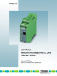
2. Set the module’s DIP switch
The switch, SW1, is located in the bottom corner of the module’s large circuit board.
SW1
RACK
EXT
WARNING: Module is ESD sensitive.
Handle accordingly.
NOTE: When using the External Power Feature, the external power and SLC power must be turned
on simultaneously.
· With the switch in the RACK position, the module draws all its power from the backplane of the
SLC system.
· With the switch in the EXT position, the module draws its 24 Vdc power from an external power
source; however, the module still draws its 5 Vdc power from the backplane.
Although your module has a jumper on its printed circuit board, this jumper is for the
manufacturer’s use only.
3. Wire your module
To wire your module, you need:
· a small, flat-blade screwdriver
· Belden 8761 (shielded, twisted pair) cable or equivalent
You do not need to remove the supplied 16-position terminal block from the module. If however,
you do remove the terminal block, use the write-on label to identify your module’s location.
Before wiring the terminal block, turn off the power, unscrew the two retaining screws at the top
and bottom of the terminal block, and carefully pry the terminal block loose.
Before removing the terminal block, take some time to plan your system:
· Ensure that the SLC 500 system is properly grounded and installed in a NEMA-rated enclosure.
8 1746sc I/O Module Installation Instructions
· Turn off the power.
· Route the field wiring away from other wiring and as far as possible from sources of electrical
noise, such as motors, transformers, contactors, and AC devices.
· Route the field wiring in grounded conduit if possible.
· Ensure that the field wiring crosses AC or power cables at a right angle.
For CE compliance, Ferrite EMI Suppressors are needed on each channel’s terminal block
connection. Apply the suppressor close to the module terminal block. A Steward Part 2882024-0A0
or equivalent is recommended.
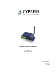
-INO4vi
Voltage output, ch. 0
0
Current output, ch. 0
1
Analog ground, ch. 0
2
Chassis ground
3
Voltage output, ch. 1
4
Current output, ch. 1
5
Analog ground, ch. 1
6
Voltage output, ch. 2
7
Current output, ch. 2
8
Analog ground, ch. 2
9
Chassis ground
10
Voltage output, ch. 3
11
Current output, ch. 3
12
Analog ground, ch. 3
13
+24 Vdc external
14
Ground external
15
Current
+
load
+
Voltage
load
-
Shielded, twisted-pair cable with shield
connected to ground only at one end
To guard against electrostatic damage
and improve module grounding,
connect a chassis ground pin directly
to a rack mounting bolt.
Ext. pwr.
supply
24 Vdc power supply if
external power is selected.
-INO4i
Not used
0
Current output, ch. 0
1
Analog ground, ch. 0
2
Chassis ground
3
Not used
4
Current output, ch. 1
5
Analog ground, ch. 1
6
Not used
7
Current output, ch. 2
8
Analog ground, ch. 2
9
Chassis ground
10
Not used
11
Current output, ch. 3
12
Analog ground, ch. 3
13
+24 Vdc external
14
Ground external
15
Current
+
load
-
Current
+
load
-
Shielded, twisted-pair cable with shield
connected to ground only at one end
To guard against electrostatic damage
and improve module grounding,
connect a chassis ground pin directly
to a rack mounting bolt.
Ext. pwr.
supply
24 Vdc power supply if
external power is selected.
1746sc I/O Module Installation Instructions 9
4. Assign your module to a slot
When assigning your module to a slot, select the module from the displayed list. If your module is
not listed, select OTHER at the bottom of the list and enter your module’s ID code at the prompt.
Catalog Number
1746sc-INO4i
1746sc-INO4vi
Module ID Code
3521
3519
5. Configure each channel
Use the low and high bytes in Output Words 4 and 5 (addresses O:e.4 and O:e.5) to configure each
channel.
0
15
Channel 2 Configuration Byte
0
0
0
0
1
1
1
1
0
0
1
1
0
0
1
1
0
1
0
1
0
1
0
1
0
0
1
1
0
0
1
1
0
1
0
1
0
1
0
1
= ±10 Vdc
= 15 Vdc
= 05 Vdc
= 010 Vdc
= 020 mA
= 420 mA
= 021 mA
= Invalid
= Engineering units
= Scaled for PID
= Proportional counts
= 1746-NO4 format
= Invalid
= Invalid
= User-defined scale
= Invalid
0
0
0
0
1
1
1
1
0
0
1
1
0
0
1
1
0
1
0
1
0
1
0
1
Output range
1 = Channel enable
Output range
0
0
0
0
1
1
1
1
Data format
Channel 3 Configuration Byte
1 = Hold last value (0 = reset*) on fault
Channel 0 Configuration Byte
Data format
1 = Hold last value (0 = reset) on fault
O:e.5
Channel 1 Configuration Byte
0
0
0
0
1
1
1
1
0
0
1
1
0
0
1
1
0
1
0
1
0
1
0
1
1 = Channel enable
Address
O:e.4
= ±10 Vdc
= 15 Vdc
= 05 Vdc
= 010 Vdc
= 020 mA
= 420 mA
= 021 mA
= Invalid
= Engineering units
= Scaled for PID
= Proportional counts
= 1746-NO4 format
= Invalid
= Invalid
= User-defined scale
= Invalid
* = Reset on Fault means the module outputs will go to zero (0) on a Rack Fault
6. Set output limits / user-defined scale (optional).
Use Output Words 6 and 7 (addresses O:e.6 and O:e.7) to set the low and high values of the output
data limits or user-defined scale (if user-defined scaling is desired). If you do not want to use these
features, set output words 6 and 7 to 0. Setting output words 6 and 7 to 0 disables limiting and
invalidates scaling.
Address
O:e.6
O:e.7
0
15
Low Value of Output Data Limit (or User-Defined Scale)
High Value of Output Data Limit (or User-Defined Scale)
10 1746sc I/O Module Installation Instructions
You cannot use output data limiting with user-defined scaling.
Important – The values in output words 6 and 7 apply to all 4 channels. If you want to use userdefined scaling or output data limiting, you must set all 4 channels to the same data format.
7. Control each channel’s signal level
Use Output Words 0-3 (address O:e.0 – O:e.3) to control the output signal level of each channel.
The output signal level depends on the data format and output range selected.
Address
O:e.0
0
15
Channel 0 Output Data Word
O:e.1
Channel 1 Output Data Word
O:e.2
Channel 2 Output Data Word
O:e.3
Channel 3 Output Data Word
The following equations show you how to convert between data value (counts) and signal level (in
mA or V):
S = {(D - D low) x (∆S) ÷ (∆D)} + S low
D = {(S - Slow) x (∆D) ÷ (∆S)} + D low
where
S =
signal level in mA or V)
Slow = minimum signal level (see Table 11 in Chapter 4)
Shigh = maximum signal level (see Table 11 in Chapter 4)
∆S = Shigh -Slow
D =
data value (counts)
Dlow = minimum data value (see Table 11 in Chapter 4)
Dhigh = maximum data value (see Table 11 in Chapter 4)
∆D = Dhigh - Dlow
1746sc I/O Module Installation Instructions 11
8. Monitor each channel’s data
Use Input Words 0-3 (addresses I:e.0 – I:e.3) to monitor the data received by your module from the
processor. When a channel is disabled, its data word is set to 0.
Address
I:e.0
0
15
Channel 0 Output Data Word
I:e.1
Channel 1 Output Data Word
I:e.2
Channel 2 Output Data Word
I:e.3
Channel 3 Output Data Word
9. Check each channel’s configuration and status
Use Input Words 4-7 (addresses I:e.4 – I:e.7) to check the configuration and status of each channel.
When a channel is disabled, its status word is set to 0.
0
15
the channel
configuration byte.
1 = Output data limiting enabled
1 = Over-limit error
1 = Operating temperature error
Channel 3 Status Word
1 = Under-limit error
I:e.7
1 = Over-range error
Channel 2 Status Word
1 = Under-range error
I:e.6
1 = Fatal channel error
Channel 1 Status Word
1 = Non-fatal channel error
I:e.5
the settings in
Channel 0 Status Word
Reflected Config Byte:
Bits 07 mirror
Address
I:e.4
12 1746sc I/O Module Installation Instructions
1746sc-INI4i & 1746sc-INI4vi
1. Determine the backplane power requirements.
Use the table below to calculate the total load on the system power supply. For more information,
see the Allen-Bradley system Installation and Operation Manual.
Backplane Current Consumed
Catalog Number
5 Vdc
24 Vdc
1746sc-INI4i
460 mA typical
0 mA
1746sc-INI4vi
570 mA typical
0 mA
2. Wire your module.
To wire your module, you need:
· a small, flat-blade screwdriver
· Belden 8761 (shielded, twisted pair) cable or equivalent
You do not need to remove the supplied 16-position terminal block from the module. If however,
you do remove the terminal block, apply the supplied write-on label to the terminal block, and use
the write-on label to identify your module’s location.
Before wiring the terminal block, unscrew the two retaining screws at the top and bottom of the
terminal block, and carefully pry the terminal block loose.
Before wiring the terminal block, take some time to plan your system:
· Ensure that the SLC 500 system is properly grounded and installed in a NEMA-rated enclosure.
· Ensure that the load resistance is <500ΩW for a current output channel and > 1 kΩW for a
voltage output channel.
· Route the field wiring away from other wiring and as far as possible from sources of electrical
noise, such as motors, transformers, contactors, and AC devices.
· Route the field wiring in grounded conduit if possible.
· Ensure that the field wiring crosses AC or power cables at a right angle.
For CE compliance, Ferrite EMI Suppressors are needed on each channel’s terminal block
connection. Apply the suppressor close to the module terminal block. A Steward Part 2882024-0A0
or equivalent is recommended.
1746sc I/O Module Installation Instructions 13
-INI4i
+
+
-
analog current
-
I IN 0 +
COM 0 SHIELD 0
SHIELD 1
+
+
-
analog current
-
I IN 1 +
COM 1 I IN 2 +
COM 2 -
Shielded, twisted-pair cable with shield
connected to ground only at one end
SHIELD 2
SHIELD 3
I IN 3 +
To guard against electrostatic damage
and improve chassis grounding,
connect one of the shield pins on the
terminal block to the rack.
-INI4vi
+
analog current
COM 3 -
+
-
-
V IN 0 +
I IN 0 +
COM 0 SHIELD 0
+
analog voltage
+
-
-
SHIELD 1
V IN 1 +
I IN 1 +
COM 1 V IN 2 +
I IN 2 +
COM 2 -
Shielded, twisted-pair cable with shield
connected to ground only at one end
SHIELD 2
SHIELD 3
V IN 3 +
To guard against electrostatic damage
and improve chassis grounding,
connect one of the shield pins on the
terminal block to the rack.
I IN 3 +
COM 3 -
3. Assign your module to a slot.
When assigning your module to a slot, select the module from the displayed list. If your module is
not listed, select OTHER at the bottom of the list and enter your module’s ID code at the prompt.
Catalog Number
1746sc-INI4i
1746sc-INI4vi
Module ID Code
3522
3520
14 1746sc I/O Module Installation Instructions
4. Configure each channel
Use the low and high bytes in Configuration Words 0-3 (addresses O:e.0 – O:e.3) to configure each
channel.
0
15
Channel 0 Configuration Word
*
*
*
*
0=
1=
0=
1=
Data format
Open circuit response
1= Autocalibration enabled
0
0
1
1
Input filter frequency
Channel 2 Configuration Word
Channel 3 Configuration Word
Unused (must set to 0)
O:e.2
O:e.3
0
0
0
0
1
1
1
1
60 Hz
50 Hz
150 Hz
500 Hz
00 = Zero on open circuit
01= Max. on open circuit
10= Min. on open circuit
11= Invalid
0
0
0
0
1
1
1
1
0
0
1
1
0
0
1
1
0
1
0
1
0
1
0
1
=
=
=
=
=
=
=
=
0
0
1
1
0
0
1
1
0
1
0
1
0
1
0
1
=
=
=
=
=
=
=
=
1 = Channel enable
Channel 1 Configuration Word
0 = Channel disable
O:e.1
Input range
Address
O:e.0
±10 Vdc
15 Vdc
05 Vdc
010 Vdc
020 mA
420 mA
Invalid
Invalid
Engineering units
Scaled for PID
Proportional counts
1746-NI4 format
User-defined scale A
User-defined scale B
Invalid
Invalid
* = Applies only to 1-5V and 4-20 mA. Select INVALID for all other ranges.
5. Set limits, scale if applicable.
Use Configuration Words 4-7 (addresses O:e.4 – O:e.7) to set the low and high values of the userdefined scale (if user-defined scaling is desired). If you do not want to use these features, set output
words 4-7 to 0. Setting output words 4-7 to 0 disables scaling.
Address
O:e.4
0
15
Low Value of User-Defined Scale A
O:e.5
High Value of User-Defined Scale A
O:e.6
Low Value of User-Defined Scale B
O:e.7
High Value of User-Defined Scale B
1746sc I/O Module Installation Instructions 15
6. Monitor each channel’s data
Use Input Words 0-3 (addresses I:e.0 – I:e.3) to monitor the data received by your module from the
input device. When a channel is disabled, its data word is set to 0.
Address 15
0
I:e.0
Channel 0 Data Word
I:e.1
Channel 1 Data Word
I:e.2
Channel 2 Data Word
I:e.3
Channel 3 Data Word
I:e.4
Channel 4 Data Word
I:e.5
Channel 5 Data Word
I:e.6
Channel 6 Data Word
I:e.7
Channel 7 Data Word
The following equations show you how to convert between data value (counts) and signal level (in
mA or V):
S = {(D - Dlow ) x (∆S) ÷ (∆D)} + S low
D = {(S - Slow) x (∆D) ÷ (∆S)} + D low
where
S =
signal level in mA or V)
Slow = minimum signal level (see Table 11 in Chapter 4)
Shigh = maximum signal level (see Table 11 in Chapter 4)
∆S = Shigh -Slow
D =
data value (counts)
Dlow = minimum data value (see Table 11 in Chapter 4)
Dhigh = maximum data value (see Table 11 in Chapter 4)
∆D = Dhigh - Dlow
16 1746sc I/O Module Installation Instructions
7. Check each channel’s configuration and status
Use Input Words 4-7 (addresses I:e.4 – I:e.7) to check the configuration and status of each channel.
When a channel is disabled, its status word will be set to 0.
0
15
the channel
configuration byte.
the settings in
1 = Operating temperature error
1 = Under-limit error
Channel 3 Status Word
1 = Operating temperature error
I:e.7
1 = Over-range error
Channel 2 Status Word
1 = Under-range error
I:e.6
1 = Fatal channel error
Channel 1 Status Word
1 = Non-fatal channel error
I:e.5
Bits 0-7 mirror
Channel 0 Status Word
Reflected Config Byte:
Address
I:e.4
1746sc I/O Module Installation Instructions 17
18 1746sc I/O Module Installation Instructions
1746sc-IA8I & 1746sc-IB8I & 1746sc-IC8I & IM8I
1. Determine the backplane power requirements.
Use the table below to calculate the total load on the system power supply. For more information,
see the Allen-Bradley system Installation and Operation Manual.
Backplane Power
All Modules
5Vdc
24Vdc
110mA
0mA
2. Wire your module.
To wire field devices to your module, follow these steps:
1. Turn off power to the I/O chassis.
2. Optional: Remove the supplied 18-position terminal block from the module. To remove the
terminal block, unscrew the two retaining screws at the top and bottom of the terminal block, and
pull the terminal block loose.
3. Wire field devices to your module as shown in the following wiring diagrams, using a maximum
wire size of 14 AWG and a maximum of two wires per terminal. The recommended terminal
screw torque is 7 to 9 in.-lb.
4. Install a wire tie in the slot below the terminal block and secure the wires.
CE Compliance Requirements
For installations requiring CE compliance, you must do the following:
· Observe the grounding guidelines provided in Allen-Bradley’s SLC 500 Installation and
Operation Manual (Allen-Bradley publication 1747-NI002).
· Connect an E-GND terminal on the module directly to a rack-mounting bolt.
· Hard wire or permanently connect the PLC to the AC mains, or provide a pin and sleeve (IEC
309) connector for connection to the AC mains.
This equipment is intended for use in over-voltage category II installations (see IEC 364-4-443),
where the rated mains supply voltage does not exceed 1000 Vac (50/60 Hz) or 1500 Vdc. If the
input power is rated above these levels, ensure that your system is isolated from the power main by
an isolation transformer (or equivalent over-voltage protection device) that has CE approval or
approval from a European test agency.
For the 1746c-IA8I, -IM8I, and -OAP8I, you must also protect against electrical shock by installing
the I/O chassis in an enclosure with an IP20 to IP29 rating per IEC 529. The enclosure should have
warning labels (hazard symbol 417-IEC-5036) and/or a mechanical disconnect to minimize the risk
of accidental shock during maintenance. Use an enclosure that can only be opened with a key or
tool.
For CE compliance, Ferrite EMI Suppressors are needed on each channel’s terminal block
connection. Apply the suppressor close to the module terminal block. A Steward Part 2882024-0A0
or equivalent is recommended.
1746sc I/O Module Installation Instructions 19
1746sc-IA8I On/Off-State Voltage Range
0 Vac*
0 Vdc
30 Vac*
20 Vdc
Off-State
80 Vac*
85 Vdc
Input State Not Guaranteed
150 Vac*
170 Vdc
On-State
* Frequency = 47 to 63 Hz
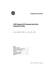
1746sc-IA8I Simplified Circuit Diagram (one circuit shown)
VAC/VDC +
24.3 kW
249 W
0.33 µF
24.3 kW
IN
1746sc-IB8I On/Off-State Voltage Range
0 Vdc
4.5 Vdc
Off-State
11.5 Vdc
Input State Not Guaranteed
32 Vdc
On-State
1746sc-IB8I Simplified Circuit Diagram (one circuit shown)
VDC +
1.91 kW
3.16 kW
IN
1.91 kW
1746sc-IC8I On/Off-State Voltage Range
0 Vdc
9.5 Vdc
Off-State
30 Vdc
Input State Not Guaranteed
1746sc-IC8I Simplified Circuit Diagram (one circuit shown)
VDC +
7.87 kW
6.65 kW
IN
7.87 kW
60 Vdc
On-State
20 1746sc I/O Module Installation Instructions
1746sc-IM8I On-Off-State Voltage Range
0 Vac*
0 Vdc
160 Vac*
170 Vdc
60 Vac*
40 Vdc
Off-State
264 Vac*
265 Vdc**
Input State Not Guaranteed
On-State
* Frequency = 47 to 63 Hz
** 276 Vdc short-term overload (1 hour)
1746sc-IM8I Simplified Circuit Diagram (one circuit shown)
499 W
VAC/VDC +
49.9 kW
0.15 µF
49.9 kW
IN
3. Assign your module to a slot.
When assigning your module to a slot, select the module from the displayed list. If your module is
not listed, select OTHER at the bottom of the list and enter your module’s ID code at the prompt.
Catalog Number
1746sc-IA8I
1746sc-IB8I
1746sc-IC8I
1746sc-IM8I
Module ID
303
324
324
304
4. Configure each channel
1746sc-IA8I
Isolated-Circuit 100/120 V ac/dc Inputs (8)
VS0 L1 or +VDC
100/120 V ac/dc
VAC/VDC
0+
VS1 L1 or +VDC
VAC/VDC
1+
VS2 L1 or +VDC
VAC/VDC
2+
VS3 L1 or +VDC
VAC/VDC
3+
IN 0
IN 1
IN 2
IN 3
E-GND
E-GND
VS4 L1 or +VDC
VAC/VDC
4+
VS5 L1 or +VDC
VAC/VDC
5+
VS6 L1 or +VDC
VAC/VDC
6+
VS7 L1 or +VDC
VAC/VDC
7+
IN 4
IN 5
IN 6
IN 7
Alternative
input device
location
VS0 L2 or DC COM
VS1 L2 or DC COM 1
VS2 L2 or DC COM 2
VS3 L2 or DC COM 3
Rack mounting bolt
VS4 L2 or DC COM 4
VS5 L2 or DC COM 5
VS6 L2 or DC COM 6
VS7 L2 or DC COM 7
For IEC Type 1+ devices
that can't support 0.7 A
of inrush current, use an
external 500 W 1W
resistor on one input line
to reduce the inrush to
250 mA.
Note The input circuits are electrically isolated from each other (the commons are NOT connected
internally). Therefore, up to eight different voltage sources (VS0VS7) may be used.
Module ID Code = 303
1746sc I/O Module Installation Instructions 21
1746sc-IB8I
Isolated-Circuit 24 Vdc Inputs (8)
VS0 +VDC
24 Vdc *
VDC
0+
VS1 +VDC
VDC
1+
VS2 +VDC
VDC
2+
VS3 +VDC
VDC
3+
IN 0
IN 1
IN 2
IN 3
E-GND
E-GND
VS4 +VDC
VDC
4+
VS5 +VDC
VDC
5+
VS6 +VDC
VDC
6+
VS7 +VDC
VDC
7+
IN 4
IN 5
IN 6
IN 7
Alternative
input device
location
VS0 DC COM
VS1 DC COM 1
VS2 DC COM 2
VS3 DC COM 3
Rack mounting bolt
VS4 DC COM 4
VS5 DC COM 5
VS6 DC COM 6
VS7 DC COM 7
Note The input circuits are electrically isolated from each other (the commons are NOT connected
internally). Therefore, up to eight different voltage sources (VS0VS7) may be used.
Module ID Code = 324
22 1746sc I/O Module Installation Instructions
1746sc-IC8I
Isolated-Circuit 48 Vdc Inputs (8)
VS0 +VDC
48 Vdc *
VDC
0+
VS1 +VDC
VDC
1+
VS2 +VDC
VDC
2+
VS3 +VDC
VDC
3+
IN 0
IN 1
IN 2
IN 3
E-GND
E-GND
VS4 +VDC
VDC
4+
VS5 +VDC
VDC
5+
VS6 +VDC
VDC
6+
VS7 +VDC
VDC
7+
IN 4
IN 5
IN 6
IN 7
Alternative
input device
location
VS0 DC COM
VS1 DC COM 1
VS2 DC COM 2
VS3 DC COM 3
Rack mounting bolt
VS4 DC COM 4
VS5 DC COM 5
VS6 DC COM 6
VS7 DC COM 7
Note The input circuits are electrically isolated from each other (the commons are NOT connected
internally). Therefore, up to eight different voltage sources (VS0VS7) may be used.
* Inputs are bipolar and may be connected without regard to polarity.
Module ID Code = 324
1746sc I/O Module Installation Instructions 23
1746sc-IM8I
Isolated-Circuit 200/240 V ac/dc Inputs (8)
VS0 L1 or +VDC
200/240 V ac/dc
VAC/VDC
0+
VS1 L1 or +VDC
VAC/VDC
1+
VS2 L1 or +VDC
VAC/VDC
2+
VS3 L1 or +VDC
VAC/VDC
3+
IN 0
IN 1
IN 2
IN 3
E-GND
E-GND
VS4 L1 or +VDC
VAC/VDC
4+
VS5 L1 or +VDC
VAC/VDC
5+
VS6 L1 or +VDC
VAC/VDC
6+
VS7 L1 or +VDC
VAC/VDC
7+
IN 4
IN 5
IN 6
IN 7
Alternative
input device
location
VS0 L2 or DC COM
VS1 L2 or DC COM 1
VS2 L2 or DC COM 2
VS3 L2 or DC COM 3
Rack mounting bolt
VS4 L2 or DC COM 4
VS5 L2 or DC COM 5
VS6 L2 or DC COM 6
VS7 L2 or DC COM 7
For IEC Type 1+ devices
that can't support 0.7 A
of inrush current, use an
external 500 W 1W
resistor on one input line
to reduce the inrush to
250 mA.
Note The input circuits are electrically isolated from each other (the commons are NOT connected
internally). Therefore, up to eight different voltage sources (VS0VS7) may be used.
Module ID Code = 304
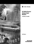
5. Interpreting your Module’s LED Indicators
On the 1746sc-IA8I, -IB8I, -IC8I, and –IM8I, each status indicator (0-7) illuminates when the
proper signal is received at the corresponding input terminal.
1746sc-IA8I
INPUT
STATUS
ISOLATED 100/120V AC/DC
1746sc-IB8I
INPUT
1746sc-IC8I
INPUT
STATUS
STATUS
ISOLATED 24V DC
ISOLATED 48V DC
1746sc-IM8I
INPUT
STATUS
ISOLATED 200/240V AC/DC
24 1746sc I/O Module Installation Instructions
1746sc I/O Module Installation Instructions 25
1746sc-OAP8I
1. Determine the backplane power requirements.
Use the table below to calculate the total load on the system power supply. For more information,
see the Allen-Bradley system Installation and Operation Manual.
Backplane Power
All Modules
5Vdc
24Vdc
110mA
0mA
2. Set your DIP Switches or shunts, if applicable.
Not applicable.
3. Wire your module.
For CE compliance, EMI Suppressors are needed on each channel’s terminal block connection.
Apply the suppressor close to the module terminal block. A Steward Part 2882024-0A0 or
equivalent is recommended.
1746sc-OAP8I Operating Voltage Range
0 Vac*
276 Vac*
74 Vac*
Operation Not Guaranteed
Recommended Operating Range
* Frequency = 47 to 63 Hz
1746sc-OAP8I Simplified Circuit Diagram (one circuit shown)
VAC
39 W
.01 µF
OUT
4. Assign your module to a slot.
When assigning your module to a slot, select the module from the displayed list. If your module is
not listed, select OTHER at the bottom of the list and enter your module’s ID code at the prompt.
Catalog Number
1746sc-OAP8I
Module ID
1905
26 1746sc I/O Module Installation Instructions
1746sc-OAP8I
Isolated-Circuit 120/240 Vac Outputs (8)
VS0 L1
Alternative
output device
location
VAC
0
VS1 L1
VAC
1
VS2 L1
VAC
2
VS3 L1
VAC
3
OUT 0
VS0 L2
OUT 1
VS1 L2
OUT 2
VS2 L2
OUT 3
VS3 L2
E-GND
E-GND
VS4 L1
VAC
4
VS5 L1
VAC
5
VS6 L1
VAC
6
VS7 L1
VAC
7
120/240 Vac
Rack mounting bolt
OUT 4
VS4 L2
OUT 5
VS5 L2
OUT 6
VS6 L2
OUT 7
VS7 L2
Note The output circuits are electrically isolated from each other (the commons are NOT connected
internally). Therefore, up to eight different voltage sources (VS0VS7) may be used.
Module ID Code = 1905
5. Interpreting your Module’s LED Indicators
On the 1746sc-OAP8I, each status indicator (0-7) illuminates when the processor commands the
module to turn on the corresponding output. The indicators do not necessarily indicate the presence
or absence of AC power at an output. The Blown-Fuse indicator illuminates when any 1 of the 8
outputs fuses blows and AC power is present.
1746sc-OAP8I
OUTPUT
STATUS
FUSE
ISOLATED TRIAC 120/240 VAC
1746sc I/O Module Installation Instructions 27
6. Checking for Blown Fuses
If a fuse blows on the 1746sc-OAP8I, the following occurs:
1.
2.
The blown-fuse LED indicator illuminates (provided your module is receiving power
from the chassis).
The module indicates to the logic controller’s input image table which fuse has blown.
This allows for fuse monitoring and smart power-down sequencing of equipment after a
circuit failure.
You can verify that a fuse has opened by visually checking the fuses, shown below. Turn all power
off, and replace blown fuses with the specified replacement part only. Substitutes are not acceptable.
Replaceable Fuses (F1F8)
3 A, 250 V, 2 AG SLO-BLO
Bussmann part C519-3A
F1
F2
F3
OAP8I
F4
F5
F6
F7
F8
28 1746sc I/O Module Installation Instructions
1746sc I/O Module Installation Instructions 29
1746sc-NI8u
1. Determine the backplane power requirements.
Use the table below to calculate the total load on the system power supply. For more information,
see the Allen-Bradley system Installation and Operation Manual.
Backplane Current Consumed
NI8U
5VDC
24VDC
120mA
100mA
2. Set your DIP switches or shunts, if applicable.
The 1746sc-NI8u module is a multi-purpose, multi-functional module, which is capable of
supporting many different input types in a very small package. There are a few shunts on the board
that allow the user to define input paths properly, which are imperative for the configuration control
to allow proper utilization of the module. JP1 through JP8 supports the current input mode options
for each of the input channels, 0 through 7, respectively. In order to define channels 4 through 7 for
voltage or RTD inputs, JP9 and JP10, must be configured properly. JP11 is used at the factory and
should not be modified. JP12 indicates whether or not RTDs are to be used in the configuration.
The module is shipped with all current input shunts in place, and the remaining shunts installed for
non-RTD inputs. The shunts are to be modified prior to installation of the module. Proper
precautions for electrostatic handling should be followed. Small needlenose pliers may be used to
configure the shunts, if needed.
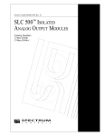
The following diagram shows the module outline defining the location of the various shunts,
looking at the primary side of the board, with the terminal block pointing up. A brief description of
each follows:
Terminal Bloc
k Header
Block
Terminal Block Header
JP1
JP2
JP3
JP4
JP5
JP6
JP7
JP8
JP9
JP10
JP11
JP12
JP1, JP2, JP3, JP4, JP5, JP6, JP7 and JP8 Setup
There are eight shunts corresponding to eight inputs, respectively, that exist to support the 0 to
20mA or 4 to 20mA current input selections. Each channel has an individual shunt (JP1- Ch. 0, JP2
- Ch. 2 through JP8 - Ch. 7). These shunts are two pin headers that only need to be connected if a
channel is to be configured for current input. If the channel is to be used for any other type
(thermocouple, millivolt, voltage for channels 0 through 3, or thermocouple, millivolt, voltage,
RTD, or resistance for channels 4 through 7), then the pins are to be left open and unconnected.
30 1746sc I/O Module Installation Instructions
Current Input
1
2
Shunt in place
Non-Current Input
1
2
Shunt removed
JP11 Setup Located in the bottom right hand corner, JP11 should always have pins 1 and 2
connected as shown. This shunt is used during manufacturing of the module, and should never be
moved by the user.
JP11
1
2 3
JP9, JP10, and JP12 Setup
The NI8u module supports up to four RTDs on channels 4 through 7. In order to properly support
RTD or resistance inputs, JP9, JP10, and JP12 have to be configured correctly. The function of JP9
and JP10 is to define the input path for the channels 4 through 7. JP9 and JP10 are four pin headers
toward the right side of the board, looking at the primary side of the board with the terminal block
pointing up. JP12 is a three pin header on the very bottom right hand corner, below JP11.
Setting For RTD or Resistance Inputs
The module will either support zero RTD or resistance inputs or four RTD or resistance inputs in
channels 4 through 7. To properly configure JP9 and JP10 for RTDs, set the shunts across pins 2
and 3 of the four pin headers. JP12 also needs to have pins 2 and 3 connected when RTDs or
resistance inputs are to be used, as shown below.
1
2
3 4
JP9
JP10
1
2 3
JP12
Setting For Non-RTD or Resistance Inputs
If RTDs are not to be used, and channels 4 through 7 are to be defined as thermocouple inputs,
current inputs, millivolt or voltage inputs, jumper pins 1 and 2 together, jumper pins 3 and 4
together, of JP9 and JP10, as defined below. JP12 also needs to have pins 1 and 2 connected when
RTDs are not in use.
1 2
3 4
JP9
JP10
1
2 3
JP12
3. Wire your module.
To wire your module, you need:
· a small, flat-blade screwdriver
· Belden 8761 (shielded, twisted pair) cable or equivalent
You do not need to remove the supplied 16-position terminal block from the module. If however,
you do remove the terminal block, apply the supplied write-on label to the terminal block, and use
the write-on label to identify your module’s location.
Before wiring the terminal block, unscrew the two retaining screws at the top and bottom of the
terminal block, and carefully pry the terminal block loose.
1746sc I/O Module Installation Instructions 31
Before wiring the terminal block, take some time to plan your system:
· Ensure that the SLC 500 system is properly grounded and installed in a NEMA-rated enclosure.
· Ensure that the load resistance is <500 Ω for a current output channel and > 1 kΩ for a voltage
output channel.
· Route the field wiring away from other wiring and as far as possible from sources of electrical
noise, such as motors, transformers, contactors, and AC devices.
· Route the field wiring in grounded conduit if possible.
· Ensure that the field wiring crosses AC or power cables at a right angle.
For CE compliance, Ferrite EMI Suppressors are needed on each channel’s terminal block
connection. Apply the suppressor close to the module terminal block. A Steward Part 2882024-0A0
or equivalent is recommended.
TOP ROW
CH0+
THERMOCOUPLE, mA,
CH0-
mV or V CABLE
Shield for CH0 and CH1
CH1+
CH1EXC4+
4-WIRE RTD CABLE
CH4+
CH4EXC4Shield for CH4 and CH5
3-WIRE RTD CABLE
EXC5+
CH5+
CH5EXC5CJCB+
CJCBCJC Sensors
32 1746sc I/O Module Installation Instructions
BOTTOM ROW
CJC Sensors
CJC A+
THERMOCOUPLE, mA,
CJC A -
mV or V CABLE
CH2+
CH2Shield for CH2 and CH3
CH3+
CH3EXC6+
CH6+
CH6EXC6Shield for CH6 and CH7
EXC7+
CH7+
CH7EXC7-
4. Assign your module to a slot.
When assigning your module to a slot, select the module from the displayed list. If your module is
not listed, select OTHER at the bottom of the list and enter your module’s ID code at the prompt.
Catalog Number
Module ID Code
1746sc-NI8u
3500
1746sc I/O Module Installation Instructions 33
5. Configure each channel
Use the low and high bytes in Configuration Words 0-7 (addresses O:e.0 – O:e.7) to configure each
channel.
0
O:e.4
Channel 4 Configuration Word
O:e.5
Channel 5 Configuration Word
O:e.6
Channel 6 Configuration Word
O:e.7
Channel 7 Configuration Word
0= Status word
1= Data word
Data format
Input range
Channel 3 Configuration Word
Open circuit response
O:e.3
Temperature units
Channel 2 Configuration Word
Channel filter frequency
Channel 1 Configuration Word
O:e.2
*RTD Type
O:e.1
Input image word
Channel 0 Configuration Word
Auto-calibration Disable
O:e.0
0
0
0= Periodic Calibration enabled
0
1= Periodic Calibration disabled
0
0
0 = 2 or 4 wire
1 = 3 wire
0
0
0 0 = 10 Hz
0 1 = 50 Hz
0
1 0 = 60 Hz
0
1 1 = 250 Hz
0
0
0 = Degrees C
1 = Degrees F
0
0
0 0 = Zero on open circuit
0 1 = Max. on open circuit
0
1 0 = Min. on open circuit
0
1 1 = Disable
0
0 0 = Engineering units x 1
1
0 1 = Engineering units x10
1
1 0 = Scaled for PID
1
1 1 = Proportional counts
1
1
* = For channels 0-3, this bit must be zero
** = Option for channels 4-7 only, for channels 0-3 invalid. 1
*** = For these input ranges, the open circuit response
1
does not apply and should be disabled.
1
1
1
1
1
1
1
1
1
1 = Channel enable
Address 15
0
0
0
0
0
0
0
0
1
1
1
1
1
1
1
1
0
0
0
0
0
0
0
0
1
1
1
1
1
1
1
1
0
0
0
0
1
1
1
1
0
0
0
0
1
1
1
1
0
0
0
0
1
1
1
1
0
0
0
0
1
1
1
1
0
0
1
1
0
0
1
1
0
0
1
1
0
0
1
1
0
0
1
1
0
0
1
1
0
0
1
1
0
0
1
1
0
1
0
1
0
1
0
1
0
1
0
1
0
1
0
1
0
1
0
1
0
1
0
1
0
1
0
1
0
1
0
1
=
=
=
=
=
=
=
=
=
=
=
=
=
=
=
=
=
=
=
=
=
=
=
=
=
=
=
=
=
=
=
=
4 to 20 mA
0 to 20 mA
± 0.05 V
± 0.10 V
± 0.50 V
± 2.0 V
0 to 5 V***
1 to 5 V***
0 to 10 V***
±10V***
Thermocouple Type J
Thermocouple Type K
Thermocouple Type T
Thermocouple Type E
Thermocouple Type R
Thermocouple Type S
Thermocouple Type B
Thermocouple Type N
RTD 100 W 385**
RTD 200 W Pt 385**
RTD 500 W Pt 385**
RTD 1000 W Pt 385**
RTD 100 W Pt 3916**
RTD 200 W Pt 3916**
RTD 500 W Pt 3916**
RTD 1000 W Pt 3916**
RTD 10 W Cu 426**
RTD 120 W Ni 618**
RTD 120 W Ni 672**
Resistance 3000 W**
Thermocouple Type C
CJC
34 1746sc I/O Module Installation Instructions
6. Monitor each channel’s data
Use Input Words 0-7 (addresses I:e.0 – I:e.7) to monitor the data received by your module from the
processor. When a channel is disabled, its data word is set to 0. To receive a channel (data word)
bit 15 of the channel’s configuration word must be set to 1.
Address 15
0
I:e.0
Channel 0 Data Word
I:e.1
Channel 1 Data Word
I:e.2
Channel 2 Data Word
I:e.3
Channel 3 Data Word
I:e.4
Channel 4 Data Word
I:e.5
Channel 5 Data Word
I:e.6
Channel 6 Data Word
I:e.7
Channel 7 Data Word
1746sc I/O Module Installation Instructions 35
7. Check each channel’s configuration and status.
Use Input Words 0-7 (addresses I:e.0 – I:e.7) to check the configuration of each channel. When a
channel is disabled, its status word will be set to 0. To receive a channel status word, bit 15 of the
channel’s configuration word must be set to 0.
I:e.1
Channel 1 Status Word
I:e.2
Channel 2 Status Word
I:e.3
Channel 3 Status Word
I:e.4
Channel 4 Status Word
0
1
0
1
=
=
=
=
0
0
0
0
0
0 = Zero on open circuit
1 = Max. on open circuit
0
0 = Min. on open circuit
0
1 = Disabled
0
0
0 0 = Engr Units x1
0
0 1 = Engr Units x10
0
1 0 = Scaled for PID
0
1 1 = Proportional counts
0
0
0
0
1
1
Valid for channels 4-7 only.
1
For these input ranges, the open circuit response 1
does not apply and should be disabled.
1
1
1
1
1
1
1
1
1
1
1
1
10 Hz input filter
50 Hz input filter
60 Hz input filter
250 Hz input filter
0
0
1
1
*=
** =
Data
Format
Open
Circuit
Channel 7 Status Word
Channel
Filter Freq.
I:e.7
1 = Under-range error
Channel 6 Status Word
1 = Open circuit error
Channel 5 Status Word
1 = Over range error
I:e.5
I:e.6
1 = Channel error
0
0
1
1
0
Channel 0 Status Word
0
0
0
0
0
0
0
0
1
1
1
1
1
1
1
1
0
0
0
0
0
0
0
0
1
1
1
1
1
1
1
1
0
0
0
0
1
1
1
1
0
0
0
0
1
1
1
1
0
0
0
0
1
1
1
1
0
0
0
0
1
1
1
1
0
0
1
1
0
0
1
1
0
0
1
1
0
0
1
1
0
0
1
1
0
0
1
1
0
0
1
1
0
0
1
1
0
1
0
1
0
1
0
1
0
1
0
1
0
1
0
1
0
1
0
1
0
1
0
1
0
1
0
1
0
1
0
1
=
=
=
=
=
=
=
=
=
=
=
=
=
=
=
=
=
=
=
=
=
=
=
=
=
=
=
=
=
=
=
=
1 = Channel enable
15
I:e.0
Input
Type
Address
4 to 20 mA
0 to 20 mA
± 0.05 V
± 0.10 V
± 0.50 V
± 2.0 V
0 to 5 V**
1 to 5 V**
0 to 10 V**
±10V**
Thermocouple Type J
Thermocouple Type K
Thermocouple Type T
Thermocouple Type E
Thermocouple Type R
Thermocouple Type S
Thermocouple Type B
Thermocouple Type N
RTD 100 W 385*
RTD 200 W Pt 385*
RTD 500 W Pt 385*
RTD 1000 W Pt 385*
RTD 100 W Pt 3916*
RTD 200 W Pt 3916*
RTD 500 W Pt 3916*
RTD 1000 W Pt 3916*
RTD 10 W Cu 426*
RTD 120 W Ni 618*
RTD 120 W Ni 672*
Resistance 3000 W*
Thermocouple Type C
CJC
36 1746sc I/O Module Installation Instructions
1746sc I/O Module Installation Instructions 37
1746sc-CTR4 / 1746sc-CTR8
1. Determine the backplane power requirements.
Use the table below to calculate the total load on the system power supply. For more information,
see the Allen-Bradley system Installation and Operation Manual.
Backplane Current Consumed
5VDC
24VDC
CTR4
175mA
75mA
CTR8
225mA
125mA
2. Wire your module.
To wire your module, you need:
· a small, flat-blade screwdriver
· Belden 8761 (shielded, twisted pair) cable or equivalent
You do not need to remove the supplied 16-position terminal block from the module. If however,
you do remove the terminal block, apply the supplied write-on label to the terminal block, and use
the write-on label to identify your module’s location.
Before wiring the terminal block, unscrew the two retaining screws at the top and bottom of the
terminal block, and carefully pry the terminal block loose.
Before wiring the terminal block, take some time to plan your system:
· Ensure that the SLC 500 system is properly grounded and installed in a NEMA-rated enclosure.
· Route the field wiring away from other wiring and as far as possible from sources of electrical
noise, such as motors, transformers, contactors, and AC devices.
· Route the field wiring in grounded conduit if possible.
· Ensure that the field wiring crosses AC or power cables at a right angle.
38 1746sc I/O Module Installation Instructions
Terminal Block Pinouts
Standard Input
Input CH0
Common CH0
Input CH1
Common CH1
Counter Enable CH0/1
Frame Ground Shield for CH0/1
Input CH2
Common CH2
Input CH3
Common CH3
Count Enable CH2/3
Frame Ground Shield for CH2/3
Input CH4
Common CH4
Input CH5
Common CH5
Counter Enable Ch4/5
Frame Ground Shield for Ch4/5
Input CH6
Common Ch6
Input CH7
Common CH7
Count Enable CH7
Frame Ground Shield for CH6/7
Quadrature Input
Note: Channels 4-7 are only available on the 1746sc-CTR8 module.
3. Assign your module to a slot.
When assigning your module to a slot, select the module from the displayed list. If your module is
not listed, select OTHER at the bottom of the list and enter your module’s ID code at the prompt.
Catalog Number
Module ID Code
1746sc-CTR4
1746sc-CTR-8
10200
10401
Note: The counter module supports Class III backplane communication. This module will not
work with the SCL5/01 processor. Please refer to your users manual for additional information
regarding ladder programming and module configuration.
4. Set jumpers
Removing the onboard jumper JP2 activates the 15 KHz hardware input filter for channels 0-3.
Removing the onboard jumper JP3 activates the 15 KHz hardware input filter for channels 4-7
(CTR8 only). You may also select from two digital filters. Refer to your operations manual for
additional information.
1746sc I/O Module Installation Instructions 39
5. Configure each channel
The input configuration word detailed below shows the configuration setup for a given channel.
Each channel has 4 associated words. Note the appropriate word address before performing
configuration.
Address
O:e.0
O:e.1
0
15
Channel 0 Configuration Word
Channel 0 Preset / M Factor
O:e.2
Channel 0 Limit / K Factor
O:e.3
Channel 0 Rate Limit / R Factor
O:e.4
Channel 1 Configuration Word
O:e.5
Channel 1 Preset / M Factor
O:e.6
Channel 1 Limit / K Factor
O:e.7
Channel 1 Rate Limit / R Factor
O:e.8
Channel 2 Configuration Word
O:e.9
Channel 2 Preset / M Factor
O:e.10
Channel 2 Limit / K Factor
O:e.11
Channel 2 Rate Limit / R Factor
O:e.12
Channel 3 Configuration Word
O:e.13
Channel 3 Preset / M Factor
O:e.14
Channel 3 Limit / K Factor
O:e.15
Channel 3 Rate Limit / R Factor
O:e.16
Channel 4 Configuration Word
O:e.17
Channel 4 Preset / M Factor
O:e.18
Channel 4 Limit / K Factor
O:e.19
Channel 4 Rate Limit / R Factor
O:e.20
Channel 5 Configuration Word
O:e.21
Channel 5 Preset / M Factor
O:e.22
Channel 5 Limit / K Factor
O:e.23
Channel 5 Rate Limit / R Factor
O:e.24
Channel 6 Configuration Word
O:e.25
Channel 6 Preset / M Factor
O:e.26
Channel 6 Limit / K Factor
O:e.27
Channel 6 Rate Limit / R Factor
O:e.28
Channel 7 Configuration Word
O:e.29
Channel 7 Preset / M Factor
O:e.30
Channel 7 Limit / K Factor
O:e31
Channel 7 Rate Limit / R Factor
CTR4
CTR8
40 1746sc I/O Module Installation Instructions
Address
O:e.x
0
15
0 = Max
1 = Preset
0 = Zero
1 = Preset
0 = Up
1 = Down
0 = 50kHz
1 = 30kHz
00 = AC
01 = 5 V
10 = 12V
11 = 24V
0 = Off
1 = On
Preset
Counter Stop
Freq. Mode
Reset Flags
Input Range
00 = UniDirect
01 = BiDirect
10 = Quad x1
11 = Quad x4
0 = +/- 32K
1 = +/- 8M
0 = Limit
1 = Scale
Count Mode
Stop on Zero
Filter
Stop in Limit
Count Size
Directrion
Roll over to
Roll under to
Scale / Limit Mode
Channel 0 Configuration Word
0 = Start
1 = Stop
0 = Off
1 = On
0 = Normal
1 = Reset
0 = Period
1 = Counter
0 = Off
1 = On
6. Set limits, scale if applicable.
A counter preset may be input to define the counter start point. The limit field may be used to flag
a high or low point in the count cycle. The frequency limit may be used to flag a particular
frequency value and toggle a status bit. The scale factor may be used to convert frequency data into
Engineering Units. The scale and preset/limit configuration bits must be set before the values are
stored. Refer to your user manual for more information about these functions.
Address
O:e.x
0
15
Counter Preset / M Factor
O:e.y
Counter Limit / K Factor
O:e.z
Rate Limit / R Factor
1746sc I/O Module Installation Instructions 41
7. Monitor each channel’s data.
Each channel has 3 associated data words and 1 status word. Counter data is provided in two
forms, count and rate. The count data is the combintation of word 1 (MSW) and 2 (LSW).
Frequency data is word 3. When the Instant/Average configuration bit is set to 0 the rate data is
based on a single count trigger. When set in Average mode the rate value is a 1 second average of
count data.
Address
I:e.0
0
15
Channel 0 MSW
CH 0 Counter Output MSW
I:e.1
Channel 0 LSW
CH 0 Counter Output LSW
I:e.2
Channel 0 Freq
CH 0 Frequency
I:e.3
Channel 0 Status
CH 0 Status
I:e.4
Channel 1 MSW
CH 1 Counter Output MSW
I:e.5
Channel 1 LSW
CH 1 Counter Output LSW
I:e.6
Channel 1 Freq
CH 1 Frequency
I:e.7
.
.
.
Channel 1 Status
I:e.28
Channel 7 MSW
CH 7 Counter Output MSW
I:e.29
Channel 7 LSW
CH 7 Counter Output LSW
I:e.30
Channel 7 Freq
CH 7 Frequency
I:e.31
Channel 7 Status
.
.
.
CH 1 Status
CH 7 Status
42 1746sc I/O Module Installation Instructions
8. Check each channel’s configuration and status.
The status word is shown below.
Address
I:e.3
0
15
Channel 0 Status Word
0 = OK
1 = Error
Counter Enable
Counter Output State
Direction
Channel 7 Status Word
Count Direction
I:e.31
CTR8
Count Max
Channel 6 Status Word
CTR4
Count Size
I:e.27
Count Limit
Channel 5 Status Word
Count Preset
I:e.23
Count Zero
Channel 4 Status Word
Frequency Max
I:e.19
Frequency Zero
Channel 3 Status Word
Frequency Limit
I:e.15
Scale / F Factor
Channel 2 Status Word
K Factor / M Factor
I:e.11
System Error
Channel 1 Status Word
Configuration Error
I:e.7
0 = Start
1 = Stop
0 = On
1 = Off
0= OK
1= Error
0 = Zero
1 = Set
0 = Zero
1 = Set
0 = 65 K
1 = 8 Meg
0 = Reset
1 = Set
0 = Reset
1 = Set
0 = Reset
1 = Set
0 = Reset
1 = Set
0 = Reset
1 = Set
0 = Reset
1 = Set
0 = Reset
1 = Set
0 = Up
1 = Down
0 = Normal
1 = Invert
1746sc I/O Module Installation Instructions 43
1746sc-NO8i & 1746sc-NO8v
The module will operate in Class 1 or Class 3 mode. This section describes how to configure the
module for Class 1 operation. Class 1 provides basic data output with no user scaling. No
configuration is required. This mode is compatible with the 1746-NO4 module.
Class 3 allows you to select units, ramping, clamping limit, alarming, safe
state options and alarm latching. For more information regarding these
features refer to the operators manual which may be found on our web site,
www.spectrumcontrols.com.
1. Backplane power requirements
Use the table below to calculate the total load on the system power supply. For more information,
see the Allen-Bradley system Installation and Operation Manual.
Catalog Number
5 Vdc
24V
w/o ext. supply
w/ ext. supply*
1746sc-NO8i
120mA
250 mA
0 mA
1746sc-NO8v
120 mA
160 mA
0 mA
* The 1746sc-NO8i and 1746sc-NO8v output modules can be connected to an external 24 Vdc
power supply to reduce backplane loading.
2. Set the module’s external power jumper JP4
The jumper, JP4, is located in the bottom corner of the module’s large circuit board near the power
supply.
!
WARNING: Module is ESD sensitive. Handle accordingly.
NOTE: When using the External Power Feature, the external power and SLC power must be turned
on simultaneously.
· With the jumper in the 1-2 position, the module draws all its power from the backplane of the
SLC system.
1
2
3
· With the jumper in the 2-3 position, the module draws its 24 Vdc power from an external power
source; however, the module still draws its 5 Vdc power from the backplane.
1
2
3
44 1746sc I/O Module Installation Instructions
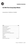
3. Wire your module
To wire your module, you need:
· a small, phillips-blade screwdriver
· Belden 8761 (shielded, twisted pair) cable or equivalent
You do not need to remove the supplied 18-position terminal block from the module. If however,
you do remove the terminal block, use the write-on label to identify your module’s location. Before
wiring the terminal block, turn off the power, unscrew the two retaining screws at the top and
bottom of the terminal block, and carefully pry the terminal block loose.
Before removing the terminal block, take some time to plan your system:
· Ensure that the SLC 500 system is properly grounded and installed in a NEMA-rated enclosure.
· Turn off the power.
· Route the field wiring away from other wiring and as far as possible from sources of electrical
noise, such as motors, transformers, contactors, and AC devices.
· Route the field wiring in grounded conduit if possible.
· Ensure that the field wiring crosses AC or power cables at a right angle.
For CE compliance, Ferrite EMI Suppressors are needed on each channel’s terminal block
connection. Apply the suppressor close to the module terminal block. A Steward Part 2882024-0A0
or equivalent is recommended.
V/I Out
0+
V/I Out
1+
V/I Out
2+
V/I Out
3+
V/I Out
4+
V/I Out
5+
V/I Out
6+
V/I Out
7+
External
+24VDC
Load
+
-
Anl Com
0
Anl Com
1
Anl Com
2
Anl Com
3
Anl Com
4
Anl Com
5
Anl Com
6
Anl Com
7
DC
Common
4. Assign your module to a slot
When assigning your module to a slot, select the module from the displayed list. If your module is
not listed, select OTHER at the bottom of the list and enter your module’s ID code at the prompt.
Catalog Number
1746sc-NO8i
1746sc-NO8v
Module ID Code
Class 1
3527
3528
Class 3
12727
12728
1746sc I/O Module Installation Instructions 45
5. Control each channel’s signal level
Use Output Words 0-7 (address O:e.0 – O:e.7) to control the output signal level of each channel.
The output signal level is fixed for Class 1 mode and identical to that of the 1746-NO4 module.
Class 1 Output Image
...
O:e.0
Channel 0 Output Data
O:e.7
Channel 7 Output Data
...
For 1746sc-NO8v: -10V to +10V = -32,768 to 32764
For 1746sc-NO8i: 0mA to 21mA = -32,768 to 32764
Refer to the operators manual for Class 3 range information.
6. Check each channel’s configuration and status
Use Input Words 0-7 (addresses I:e.0 – I:e.7) to check the configuration and status of each channel.
When a channel is disabled, its status word is set to 0.
Address
I:e.0
15
0
Channel 0 Input Status Word 1
...
I:e.7
...
Channel 7 Input Status Word 1
Bit settings in the status word
15 14
13 12
11 10
9
8
7
6
5
4
3
2
1
0
Channel Enable
Units
Output Range
0 = OK
1 = Failure
0 = OK
0 = OK
1
=
Open
1 = Fatal Error
0 = OK
1 = Reseting
Not Used
24V Power
SLC Status
Current Loop
Channel Configuration Word
Channel Status
Address
I:e.x
000 = Engineering
001 = Scaled for PID
010 = Prop. Counts
*011 = NO4 Comp. Mode
100 = User Defined
0 = Off
101 = Not Used
1 = On
110 = Not Used
*000 = +/- 10V
111 = Not Used
001 = 1-5V
010 = 0-5V
* Class 1 defaults
011 = 0-10V
*100 = 0-20mA
101 = 4-20mA
110 = 0-21mA
111 = Not Used
46 1746sc I/O Module Installation Instructions
1746sc I/O Module Installation Instructions 47
48 1746sc I/O Module Installation Instructions
Visit our Web Site or ask your distributor about these other Allen-Bradley compatible products from
Spectrum Controls:
Catalog No.
Description
1746sc-NO8i
Analog Outputs (8)
Current only
1746sc-NO8v
Analog Outputs (8)
Voltage only
1746sc-CTR4
(4) General Purpose 50kHz Counter
or Turbine Flowmeter
1746sc-CTR8
(8) General Purpose 50kHz Counter
or Turbine Flowmeter
1746sc-NI8u
Universal Analog Inputs (8)
1746sc-INI4vi
Isolated-Channel Analog Inputs (4)
Each Current or Voltage Selectable
1746sc-INI4i
Isolated-Channel Analog Inputs (4)
Current only
1746sc-INO4vi
Isolated-Channel Analog Outputs (4)
Each Current or Voltage Selectable
1746sc-INO4i
Isolated-Channel Analog Outputs (4)
Current only
1746sc-IA8I
Isolated-Circuit 100/120 Vac/dc Inputs (8)
1746sc-IB8I
Isolated-Circuit 24 Vdc Inputs (8)
1746sc-IC8I
Isolated-Circuit 48 Vdc Inputs (8)
1746sc-IM8I
Isolated-Circuit 200/240 V ac/dc Inputs (8)
1746sc-OAP8I
Isolated-Circuit 120/240 Vac Outputs (8)
1771sc-IMI16
Isolated-Circuit 200/240 Vac/dc Inputs (16)
1771sc-OMI16
Isolated-Circuit 120/240 Vac Triac Outputs (16)
Each Fuse Protected
1771sc-IFE32
(32) Single-ended Analog Inputs or
(16) Differential, Current or Voltage
The ENCOMPASS logo is a trademark of Rockwell Automation. SLC 500 is a trademark of AllenBradley Company. Copyright © 2000, 2001 Spectrum Controls, Inc. All rights reserved. Specifications subject to change without notice. Printed in U.S.A. Publication 0100081-04 Rev. D
November 1, 2001.
Corporate Headquarters
P.O. Box 5533,
Bellevue, WA 98006
Fax: (425) 641-9473
Tel: (425) 746-9481
Midwest/Northeast Sales Office
48945 Van Dyke, 4B
Utica, MI 48317
Fax: (586) 731-2715
Tel: (586) 731-2397
Southeast Sales Office
5300 Regency Lake Ct.
Sugar Hill, GA 30518
Fax: (770) 614-5886
Tel: (770) 614-5885
Web Site: http://www.spectrumcontrols.com • Email: [email protected]