Transcript
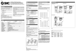
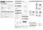
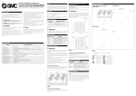
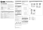
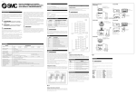
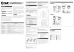
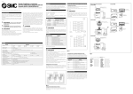
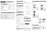
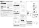
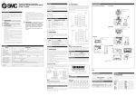
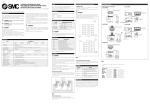
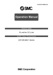
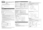
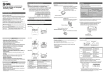
060A/Eng
Refer to the catalogues for each solenoid valve for details.
Specifications
Model
EX120-STA1-XP
EX121-STA1-XP
EX122-STA1-XP
Output point
Output style
Connecting load
Residual voltage
Power supply voltage
Current consumption
Weight (or less)
Operating ambient temperature
Operating ambient humidity
Vibration resistance
Impact resistance
Noise resistance
Withstand voltage
Insulation resistance
Operating atmosphere
Protection class
16 points
Transistor style (NPN open collector style)
DC24V, Solenoid valve with lamp-surge voltage protection circuit of 2.1W or less
0.4V or less
DC24V+10%, -5%
0.3A or less (inside unit)
170g
190g
180g
0~+50°C
35~85%RH (No dew allowed)
5G (According to JIS C0912)
10G (According to JIS C0911)
1000Vp-p pulse width 1µS, leading 1nS
AC1000V 50/60Hz for 1 min. between the terminal and the case
More than 2MΩ or more (DC500V) between the terminal and the case
No corrosive gas
IP40
54
Double
2
Double
1
64
Station
D
U
SI unit
Output No.
9
8
7
6
5
4
3
2
1
0
Connected to
24V supply power cable
0V supply power cable
Transmission path (+)
Transmission path (-)
Grounding conductor and shield
Wiring (Fig 1)
CAUTION
•••
•••
•••
•••
•••
•••
•••
•••
•••
•••
B
A
Va
A
Va
A
B
A
B
A
SI unit
Station
Double
5
Single
9.5
G(PF)1/2
1) EX120-STA1-XP
4
Single
3
Double
2
Double
1
LED
Wiring of the signal cables
Wiring of twisted pair cable should follow the drawing shown in Fig
1. Use cable recommended by OMRON Corporation.
Master
unit
SI
unit
SI
unit
15
2
Address setting
switch
Terminal LED
block
Terminal
block
D
6.2
64
Fig 2
2. Non standard wiring (mixed wiring)
Mixed wiring is available as a non-standard option. If mixed wiring is
specified, the positions of the single and double solenoids on the manifold must be indicated when ordering.
15
6.2
G(PF)1/2
LED display
LED Name
RUN
(65.5)
3) EX122-STA1-XP
Address setting
switch
64
Power of the product and all other equipment should be turned off
while wiring.
Tighten the wiring with terminal screw completely. The terminal screw
for connection is M3. Use appropriate crimp-style terminal for the
terminal screw. Short circuit, fire, and malfunction will be caused if
terminal screw is not tightened enough.
Avoid incorrect wiring. It may damage the product and/or other
equipment.
Ensure that the FG terminal is correctly earthed.
Power with correct capacity should be prepared by considering the
in-rush current when starting.
Influence of noise should be avoided for the wiring. Wiring should be
separated from power cables and high voltage cables.
6.2
60.8
Terminal name
24V
0V
+
–
FG
3
36
If solenoid valves, other than those stated in the chart above are used,
SMC offers no guarantee against malfunction of the SI unit, nor if any
load, other than solenoid valves, is used.
4
Single
SI unit
SI unit
Output No.
Terminal block
Specifications
Item
CAUTION
5
Single
54
Thoroughly read this manual and operate the product within the specified range. Follow the instructions.
Do not drop or impart any impact to the product.
Use within specified voltage range. Use outside of specified voltage
will cause malfunction, damage to unit, electric shock, and fire.
Do not touch the terminals or internal circuit board while they are
energized. It may cause malfunction, damage to unit, and electric
shock.
The product specified here is designed to be used in standard factory
automation equipment. Do not use in machinery and/or equipment
where operators may be injured, and malfunction or failure may cause
loss of life.
Do not disassemble to repair or modify the product.
Double
69.1
63.8
CAUTION
B
A
Va
A
Va
A
B
A
B
A
60.8
Applicable solenoid valve
VQ1000, VQ2000
VQ1000, VQ2000, SX3000, SX5000,
SY3000, SY5000
SX3000, SX5000, SY3000, SY5000
•••
•••
•••
•••
•••
•••
•••
•••
•••
•••
69.1
63.8
9
8
7
6
5
4
3
2
1
0
36
EX122-STA1-XP
WARNING
Terminal
block
U
Applicable solenoid valves
SI unit
EX120-STA1-XP
EX121-STA1-XP
Address setting
switch
LED
The following master unit is required to operate SYSBUS wire system:
C500-RM201
C200H-RM201
Note: Refer to the OMRON Corporation User Manual for full details.
60.8
injury or loss of life.
Use within operating ambient temperature. Do not use where temperatures can rapidly change even though it is within the specifications.
Foreign objects should be prevented from entering the product.
Contamination by foreign objects, such as wire chips will cause fire,
breakage, and malfunction.
Use within the operating environment of the protection structure.
Avoid using IP40 where water or oil, etc. can be splashed. IP40 is
achieved by mounting on manifold solenoid valve and process wire
entry correctly.
Carry out regular checks to confirm correct operation. Safety may not
be maintained by unintentional malfunction or incorrect operation.
63.8
WARNING: Operator error could result in serious
Applicable PLC
22.5
Operator error could result in injury or
equipment damage.
2) EX121-STA1-XP
Name of each part and dimension
54
CAUTION :
Products exist that can only be mounted from one side of the manifold. Please refer to the current catalogue for each solenoid valve.
When the number of stations on a VQ, SX manifold are 8 or less the
internal wiring will default to DOUBLE solenoid wiring.
36
These safety instructions are intended to prevent a hazardous situation
and/or equipment damage. These instructions indicate the level of
potential hazard by label of “CAUTION”, “WARNING”.
To ensure safety, be sure to observe ISO, JIS and other safety practices.
This SI unit is able to connect to OMRON Corp. PLC, SYSMAC C(CV)
series SYSBUS Wire system.
This SI unit has 16 output points (1 station). Maximum is 512 I/O
points (32 stations) per PLC master unit.
9.5
15
63.5
Content
Normal operation
PLC/Operation: Light
Normal transmission: Blink
Abnormal transmission: Light
T/R
ERR
Address setting (Fig 3)
Power should be turned off to set address.
Open the SI unit cover, adjust by turning the address setting switch
using a small bladed screwdriver. Setting range is 0~31. It is not possible to set address overlap.
ON
Fig 4
Fig 1
Address
End station setting
Hold/Clear
Wiring of power supply
Ensure that the power is within the specified voltage range.
Ensure that the cable is capable of supporting the solenoid and SI unit
in terms of rating.
Hold/Clear setting
For additional information please contact your local SMC office, see
below:
Set whether maintaining SI unit output condition or tune off all of it
when communication error is generated.
When you enquire about the product, please contact the following
SMC Corporation:
ENGLAND
Phone 01908-563888
TURKEY
Phone 212-2211512
ITALY
Phone 02-92711
GERMANY Phone 6103-402-0
HOLLAND
Phone 020-5318888
FRANCE
Phone 01-64-76-10-00
SWITZERLAND Phone 052-396-31-31
SWEDEN
Phone 08-603 07 00
SPAIN
Phone 945-184100
AUSTRIA
Phone 02262-62-280
Phone 902-255255
IRELAND
Phone 01-4501822
GREECE
Phone 01-3426076
DENMARK Phone 70 25 29 00
FINLAND
Phone 09-68 10 21
NORWAY
Phone 67-12 90 20
BELGIUM
Phone 03-3551464
POLAND
Phone 48-22-6131847
Hold/Clear setting
Clear
Hold
Fig 3
SW6
1
0
End station setting
Set the address as follows by SW1~5.
Corresponding SI unit output and solenoid valve
1. Standard wiring
The outputs of the SI unit are assigned from the D side (down)
solenoid valve in the order 0, 1, 2, etc.
The SI unit can be mounted from the direction of the D side or the U
side (up).
Node address
0
1
2
3
SW1
0
1
0
1
SW2
0
0
1
1
SW3
0
0
0
0
SW4
0
0
0
0
SW5
0
0
0
0
1
1
1
1
1
~
Safety Instructions
Part identification (Fig 4)
CAUTION
22.5
This manual should be read in conjunction with the current product catalogue
Outline
22.5
Installation and Maintenance Manual
EX12*-STA1-XP Series (OMRON SYSMAC C (CV)
Series, SYSBUS Wire System)
For future reference, please keep this manual in a safe place
31
Turn on both SW7 and 8 when unit is at the end station.
End station setting
ON
OFF
SW7
1
0
SW8
1
0