1
A General Toolkit for “GPUtilisation” in SME Applications
Deliverable 4.7
GPUtilisation Toolkit
User Manual
Theme:
SME-2011-1
Project Number: 286545
Deliverable ID:
4.7 – Part 1
Deliverable Name:
GPUtilisation Toolkit User Manual
Submission Date:
30/07/2013
COVER AND CONTROL PAGE OF DOCUMENT
Project Acronym:
GPSME
Project Full Name:
A General Toolkit for “GPUtilisation” in SME Applications
Document id:
4.7
Document name:
GPUtilisation Toolkit User Manual
Version:
3.0
Submission date:
30/07/2013
Editor:
Organisation:
Valeriu Codreanu
Rijksuniversiteit Groningen
GPUtilisation Toolkit Design Document
Page iii
Table of Contents
Table of Contents .............................................................................................................................. iii
Executive summary ............................................................................................................................ v
1. Introduction ................................................................................................................................... 6
1.1 Purpose of this document .................................................................................................................. 6
1.2 Document Overview .......................................................................................................................... 6
1.3 Target audience ................................................................................................................................. 6
1.4 Terminology and definitions .............................................................................................................. 6
1.5 Key Stakeholders ................................................................................................................................ 6
2. Getting started ............................................................................................................................... 8
2.1 Installation requirements................................................................................................................... 8
2.2 Installing the toolkit ........................................................................................................................... 9
2.3 Using the command-line options ....................................................................................................... 9
2.4 Key concepts/resources used within GPSME................................................................................... 10
2.5 Current status .................................................................................................................................. 12
2.6
Constraints .................................................................................................................................. 13
3. Using the GPSME toolkit ............................................................................................................... 14
3.1 7-point 3D heat equation using the GPSME toolkit ......................................................................... 14
3.2 SME code working example ............................................................................................................. 18
3.3 Example Makefile for multi-file support .......................................................................................... 19
4. Detailed Design ............................................................................................................................ 21
4.1 System and execution model ........................................................................................................... 21
4.2 GPSME Pragmas ............................................................................................................................... 22
4.2.1 New pragmas............................................................................................................................. 23
4.3 Input languages ................................................................................................................................ 24
4.4 Output languages ............................................................................................................................. 24
4.5 Loop management ........................................................................................................................... 25
4.5.1 Loop pattern classification ........................................................................................................ 25
4.6 Memory management ..................................................................................................................... 27
5. Implemented features .................................................................................................................. 28
5.1 Extended Mint’s input and output ................................................................................................... 28
5.2 Known limitations ............................................................................................................................ 28
GPUtilisation Toolkit Design Document
Page iv
5.3 In future releases ............................................................................................................................. 28
6. Writing code for parallelisation .................................................................................................... 29
6.1 Dealing with external dependencies................................................................................................ 29
6.1.1 Working with the toolkit locally ................................................................................................ 30
6.1.2 Working with the remote server ............................................................................................... 31
6.2 Handling difficult C++ constructs ..................................................................................................... 33
6.2.1 Loop parallelisation ................................................................................................................... 33
6.2.2 Data transfer and memory constraints ..................................................................................... 33
6.2.3 Conditional logic ........................................................................................................................ 34
6.2.5 Function calls ............................................................................................................................. 35
Appendix B. GPSME interface descriptions ....................................................................................... 49
Reference ........................................................................................................................................ 50
GPUtilisation Toolkit Design Document
Page v
Executive summary
This document presents the User Manual of the GPSME Toolkit. The GPSME Toolkit is part of the FP7
project entitled “A General Toolkit for “GPUtilisation” in SME Applications”. The project is developed
by a consortium composed of two research groups (University of Bedfordshire, UK and
Rijksuniversiteit Groningen, the Netherlands) and 4 SME partners. The goal of the project is to
develop a toolkit that will help SMEs improve the quality and reduce the time-to-market for their
new and existing products. The GPUtilisation toolkit will automate the conversion of existing
sequential CPU code to an optimal GPU implementation. The initiative of this project came from the
demands of the 4 SME participants. While providing services in different areas, they all face a
common problem: the quality of their products has been inhibited by a lack of computing power.
The lack of computing power is not an inherent limitation for the actual SMEs, but is mostly a
limitation imposed by the equipment that the users of their products are expected to have – in other
words, the product developed is constrained by the computational resources of the likely user base.
Hence, the availability and affordability of the equipment necessary to use the SME’s products can
affect their marketing and become a major obstacle to their competitiveness in the future.
From a technological point of view, through the GPSME toolkit the consortium will research and
develop techniques based on automatic parallelization for modern day GPUs. As a foundation for the
GPSME toolkit, the consortium will use a sophisticated open source complier platform ROSE
(www.rosecompiler.org), and improve the functions and optimize the algorithms of an existing Cto-CUDA translator MINT. In the proposed GPSME software structure, the input to the toolkit is
C/C++ source code, which would be read and transferred as an AST (Abstract Syntax Tree) by the
ROSE frontend. At the base of the GPSME toolkit is a set of #pragma user annotations that are
meant to guide the toolkit to a closer-to-optimal tailor-made implementation. By using the
information provided by the user through the annotations, the toolkit will carry out different
transformations on the AST. The output from the toolkit is CUDA/OpenCL source code obtained by
unparsing the transformed AST through the ROSE back-end. The toolkit will operate by creating
optimized GPU kernels out of annotated parallelizable loops.
In this document, Section 1 provides a brief introduction of the GPSME toolkit andthe purpose of
this document. Section 2 presents the installation instructions for the toolkit, as well as some of the
key concepts. Section 3 gives two use-cases for the GPUtilisation toolkit. In Section 4, a specification
of each important component of this toolkit is presented. Section 5 describes the current limitations
and the future improvements of the toolkit.
GPUtilisation Toolkit Design Document
Page 6
1. Introduction
1.1 Purpose of this document
This document is the User Manual (UM) for the GPSME Toolkit developed under the FP7 EU project
entitled: A General Toolkit for “GPUtilisation” in SME Applications (GPSME). This document is meant
to help SME users become more familiar with the GPSME toolkit and with its programming model.
The set of user-annotations will also be explained, and some working examples will be given later in
this text.
1.2 Document Overview
This document is intended for the SME developers. In Section 2, the design overview of the
GPUtilisation toolkit is provided. Section 3 gives a general description of the system architecture of
the GPUtilisation toolkit. In section 4, the detailed design of each component in this toolkit is
presented. Section 5 describes the testing strategy of this toolkit.
1.3 Target audience
The target audience of the User Manual are the developers and scientists from the SMEs who want
to learn how to use the toolkit. They are shown the handles by which they can tune their existing
and future algorithms towards the efficient use of GPGPU hardware.
1.4 Terminology and definitions
Throughout this document, certain terms have a very specific meaning:
ROSE – open-source compiler infrastructure developed at LLNL (Lawrence Livermore
National Laboratory) with the goal to help the research community in designing source-tosource translators
GPU (Graphics Processing Unit) – highly data-parallel processing hardware, typically used for
games, but lately used more extensively in scientific applications
CUDA is the parallel computing platform and programming model supported by NVIDIA on
its range of GPUs
OpenCL is a parallel computing platform and programming model promoted by the Khronos
group and supported by NVIDIA, AMD, Intel and other hardware vendors on GPUs or on
multi-core CPUs
Mint is a basic C-to-CUDA translator, based on ROSE, that is optimized towards sequential C
– to – parallel CUDA source-to-source translation for stencil-based applications
1.5 Key Stakeholders
The key stakeholders are:
Biocomputing Competence Center,
Italy
http://www.b3c.it/
ImageMetry Ltd.
Czech Republic
http://www.imagemetry.com/
GPUtilisation Toolkit Design Document
Medicsight
United Kingdom
http://www.medicsight.com/
RotaSoft Ltd.
Turkey
http://www.rotasoft.com.tr/
AnSmart Ltd.
United Kingdom
http://www.ansmart.co.uk/
University of Bedfordshire
United Kingdom
http://www.beds.ac.uk
University of Groningen
Netherlands
http://www.rug.nl/
Page 7
GPUtilisation Toolkit Design Document
Page 8
2. Getting started
In this chapter we outline the first steps in using the GPSME toolkit. In the first part of the chapter
information about the toolkit’s installation is provided, while in the second part some basic
command-line usage of the tool is presented.
2.1 Installation requirements
The GPUtilisation toolkit is designed to work in the Linux environment, and is based on the
foundation provided by the ROSE platform. Below we list the requirements from both a hardware
and software standpoint:
Hardware requirements:
X86/x64 CPU 1.5GHz CPU
Graphic card supporting CUDA (http://developer.nvidia.com/cuda/cuda-gpus) or a
computing platform supporting OpenCL - multi-core CPU or supported GPU
(http://www.khronos.org/conformance/adopters/conformant-products/)
Ram size over 4GB
Hard disk space of over 1GB
Software requirements:
Linux Ubuntu (10.04 or higher)
ROSE infrastructure
git
subversion
wget
g++ version 4.0.x to 4.4.x
gfortran version 4.2.x to 4.4.x
BOOST version 1.36.0 to 1.45.0
JAVA version >=1.5.0_11
Autoconf version >=2.59
Automake version >= 1.96
GNU Libtool version >= 1.5.6
GNU Flex, GNU Bison, Doxygen, ghostscript, DOT(GraphViz), LaTex, zgrviewer.
Note: The majority of the software listed above is actually used for the successful installation of
ROSE. Once the ROSE library has been generated, the GPSME toolkit only requires BOOST and JAVA
on the Ubuntu platform. However, considering the diversity of ROSE versions, it is recommended
that users download and install ROSE on their machine before using the toolkit.
GPUtilisation Toolkit Design Document
Page 9
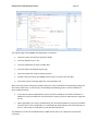
2.2 Installing the toolkit
The steps required to have a working installation of the GPSME toolkit are summarized below:
1. Download and install a version of the Boost library (between 1.36 and 1.45) from
www.boost.org/users/download. More information about the specific issues with installing
the different versions of Boost can be found in: www.boost.org.
2. Download and install one of the recent versions of ROSE. The GPSME toolkit development
started with the ROSE toolkit version 16568 from 3/10/2011. This version is recommended,
but newer versions will typically be supported also. Instructions for the ROSE installation can
be found in the ROSE user manual (http://rosecompiler.org/ROSE_UserManual/ROSEUserManual.pdf) under Section 2.
3. Download and untar the GPSME toolkit. To successfully install the toolkit, the rose.mk file
has to be modified to reflect the specific pre-required installation paths. The following paths
should be provided:
a. ROSE_INSTALL_DIR
b. BOOST_INSTALL_DIR
c. JAVA_INCLUDE
4. cd to the GPSME src directory and type make to compile the GPSME toolkit
5. Set up the LD_LIBRARY_PATH environment variable to include the paths to the boost library
and java library. For example:
a. export BOOST_INSTALL= /yourpath/boost_1_4
b. export LD_LIBRARY_PATH=$BOOST_INSTALL/lib:$LD_LIBRARY_PATH
c. export JAVA_HOME= /usr/lib/jvm/java-6-openjdk
d. export LD_LIBRARY_PATH=$JAVA_HOME/jre/lib/amd64/server:$LD_LIBRARY_PATH
After successfully completing these steps the GPSME toolkit installation should be complete. The
next step is to experiment with the GPSME programming model.
2.3 Using the command-line options
The toolkit is used to generate a CUDA or OpenCL output from an annotated C/C++ source file. The
output code does not rely on any external library that should be loaded at runtime, as the GPSME
toolkit solely relies on the libraries of the target language, namely the CUDA runtime library when
targeting CUDA, or the OpenCL runtime library when targeting OpenCL. These libraries should be
present at the locations contained in the LD_LIBRARY_PATH environment variable.
The GPSME toolkit uses the command-line interface (CLI) to invoke the program in the Linux
environment. Each command for the GPSME toolkit starts with the executable name, which is
“GPSMETranslator”. The executable name is followed by the name of the source file that should be
translated and also by an option flag that controls the output of the translator. These are the three
mandatory fields, with other fields being optional.
Use the following rules when specifying command line options:
Enter options in any order. Each option is separated by spaces.
Be consistent with upper case and lower case.
Enter file names in the specified order that is prescribed by the command line program.
Use lower case for all file extensions.
There is an “options” modifier at the end of the command line, which controls the various
options of the translator.
GPUtilisation Toolkit Design Document
Page 10
An example for the usage of the toolkit is:
$ ./GPSMETranslator <input_source_file>.<extension> <output_format> [options]
Where:
<input_source_file> - represents the filename of the source code to be processed.
<extension> can currently be either .c or .cpp. Based on the provided extension, the GPSME
toolkit will call the necessary front-end parser from the ROSE infrastructure, and will
generate the AST for the input source.
<output_format> is a mandatory parameter that selects whether the output format is CUDA
or OpenCL. The toolkit can thus be called like:
o $ ./GPSMETranslator matMul.c –cl to generate an OpenCL version of the matMul.c
input C program
o $ ./GPSMETranslator Heat3D.cpp –cu to generate a CUDA version of the Heat3D.cpp
input C++ program
[options] is an optional list of arguments that trigger certain optimizations, or guide the
compiler with extra knowledge. These set of options will further be extended during the
development of the project. Some of the options are:
o Optimization options:
opt:shared turns on shared memory usage to improve performance
opt:register turns on register reuse to avoid register fill/spill
o Platform-specific:
platform:xxx helps the translator produce a code tailored to a specific
output platform (e.g. platform:cc30 tunes the output to an NVIDIA computecapability 3.0 compatible device)
Apart from this simple use-case, users can also make use of Makefiles, in order to compile multi-file,
multi-rule projects. A sample Makefile will be shown farther in this document.
Besides this Linux client-based usage scenario, the toolkit will be provided with a web-server frontend. In the first versions of the toolkit the web-service will be accessible by the SMEs through normal
web queries, with later versions increasing the automation and providing scripted access to the webserver. The purpose of this web-server approach is to provide platform independence to the SMEs.
This way, even if the toolkit is normally usable only in the UNIX environment, SMEs who have their
application on other platforms (e.g. Windows, Mac OSX) can still use it. Some further constraints will
be applied for this approach (e.g. target operating system-specific libraries must not be used in the
files that need to be parallelized, as they will not be found on the source Linux system by the frontend parser).
2.4 Key concepts/resources used within GPSME
Below are listed some of the most important concepts and the resources used within the GPSME
project.
ROSE Infrastructure: Open source compiler infrastructure to build source-to-source program
transformation and analysis tools.
GPUtilisation Toolkit Design Document
Page 11
Particularly well suited for building custom tools for static analysis, program optimization,
arbitrary program transformation, domain-specific optimizations, complex loop
optimizations, and performance analysis.
ROSE builds and provides access to an abstract syntax tree (AST) that is well suited to
source-to-source transformation (ROSE does not lose any information about the structure of
the original source code).
Nearly all types of optimizations are included in ROSE and can be used via simple function
calls to some interfaces from the translators. Examples of packages within ROSE which can
be used:
o Call Graph analysis library
o CFG analysis
o Alias analysis
o Extensive loop transformation API with capabilities including:
Dependence and transitive dependence analysis
Profitability analysis
Transformation framework
More information about the ROSE infrastructure can be found at http://rosecompiler.org
Mint Translator: A domain-specific source-to-source translator between C and CUDA.
Based on ROSE and targeting CUDA.
Domain-specific targeting stencil-based methods. Stencil-based methods are the base for
many algorithms that numerically solve partially differential equations (PDEs), and are thus
widely used in scientific applications.
Uses some user-guided annotations in the form of pragmas. These pragmas give more
specific knowledge to the translator.
Achieves about 80% of hand-optimized code performance for stencil methods when
targeting the latest NVIDIA boards.
AST manipulation:
The GPSME toolkit works by modifying the input files’ abstract syntax tree (AST).
The AST is passed to the GPSME toolkit in the mid-end of ROSE, after the input file is parsed
by the EDG front-end (C/C++ front-end from ROSE). The resulting AST is complete,
incorporating all the semantics from the input source-file. This is due to the vast number of
the ROSE intermediate representation nodes (IR nodes) that are required to model every
aspect of the input source-file inside the AST.
Loop transformations:
The GPSME toolkit relies on the dependency testing from ROSE to check if a particular loop
is safely parallelizable or not.
Apart from checking the safeness of parallelization, ROSE also provides an API for loop
dependency elimination that employs techniques such as: loop skewing, loop reversal, loop
interchange, loop fusion, etc.
Each transformation modifies the AST accordingly, and after the dependency has been
eliminated, the loop nest can be safely parallelized.
CUDA/OpenCL runtime:
Based on the user-provided pragma annotations, the GPSME translator will issue CUDA or
OpenCL runtime calls in the output programs.
GPUtilisation Toolkit Design Document
Page 12
These runtime calls control the creation of the data structures on the GPU, the copying
between the host processor’s memory and the device memory, and the copying of results
from device memory to the host memory.
Launching of compute kernels on the accelerator device.
Communication with the various command and data queues from the OpenCL runtime.
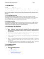
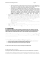
2.5 Current status
The development environment of the GPSME toolkit has been built on top of the ROSE platform for
designing source-to-source translation. The ROSE platform is designed solely for Linux, and thus this
is the operating system of choice for the GPSME toolkit. A web-service scenario that extends this
initial limitation to multiple platforms has been described in Section 2.3 Using the command-line
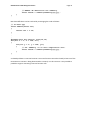
options. The general architecture of the GPSME toolkit is presented in Figure 1: General architecture
of the GPSME toolkit. The first version of the GPSME toolkit to support C/C++ input source files and
capable of outputting a CUDA/OpenCL source file has been implemented. This version of the GPMSE
toolkit is built on top of a similar toolkit called “Mint”. Mint is only capable of translating a single C
source file into a CUDA file. Also, Mint is limited to some domain-specific problems, namely stencil
computation. The extended functions proposed so far in the GPSME toolkit make it capable of
reading basic C++ files and generating OpenCL files.
GPUtilisation Toolkit Design Document
Page 13
Figure 1: General architecture of the GPSME toolkit
2.6 Constraints
The main constraints of the current version of the GPSME toolkit are:
Only works natively on the Linux platform due to the availability of ROSE libraries
Unable to support all the features of the C++ programming language
Unable to parallelize multiple types of loop patterns, being limited to a 3D type of loop
pattern
as
will
be
seen
in
the
source
examples
from
Section
GPUtilisation Toolkit Design Document
3. Using the GPSME toolkit.
Page 14
GPUtilisation Toolkit Design Document
Page 15
3. Using the GPSME toolkit
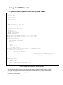
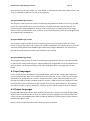
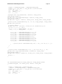
3.1 7-point 3D heat equation using the GPSME toolkit
void Heat3D::execute(void)
{
int n = 256;
int m = 256;
int k = 256;
float c0=0.5;
float c1=-0.25;
float*** Unew; float*** Uold;
Unew= alloc3D(n+2, m+2, k+2);
Uold= alloc3D(n+2, m+2, k+2);
init(Unew, n+2, m+2, k+2);
init(Uold, n+2, m+2, k+2);
int T= 20;
int nIters = 0;
double time_elapsed ;
double Gflops=0.0;
#pragma mint copy(Uold, toDevice, (n+2), (m+2), (k+2))
#pragma mint copy(Unew, toDevice, (n+2), m+2, (k+2))
#pragma mint parallel
{
time_elapsed = getTime();
int t=0;
while( t < T ){
t++;
int x, y, z;
//7-point stencil
#pragma mint for nest(all) tile(16,16,16) chunksize(1,1,16)
for (z=1; z<= k; z++){
for (y=1; y<= m; y++){
for (x=1; x<= n; x++) {
Unew[z][y][x] = c0* Uold[z][y][x] + c1 * (Uold[z][y][x-1] + Uold[z][y][x+1]+
Uold[z][y-1][x] + Uold[z][y+1][x] +
Uold[z-1][y][x] + Uold[z+1][y][x]);
}
}
}
#pragma mint single
{
REAL*** tmp;
tmp = Uold; Uold = Unew; Unew = tmp;
nIters = t ;
}
}//end of while
Figure 2: GPSME toolkit example for a 3D heat equation
}//end of parallel region
#pragma mint copy(Uold, fromDevice, (n+2), (m+2), (k+2))
This section aims at providing the user an understanding of using the GPSME toolkit pragmas.
Currently, the pragmas involved are inherited from the Mint project, but they will be further
extended during the lifetime of the project, in order to provide increased flexibility and the ability to
fine-tune the output code.
GPUtilisation Toolkit Design Document
Page 16
As can be seen in the modified source file, only 4 pragmas are needed to optimally transform the 3D
heat equation from its CPU to an optimal GPU implementation. The used pragmas have the
following meaning:
#pragma mint copy
o
First two pragmas of type copy command the transfer of the input arrays from the
host to the device memory (Unew and Uold). toDevice is the direction of transfer and
n+2,m+2,k+2 are the three dimensions of each array.
o
The last pragma of type copy transfers the result back to host-memory space by
using the modifier fromDevice.
#pragma mint parallel
o
This pragma indicates the start of a parallel region. This region encloses the kernel
that should be parallelized.
#pragma mint for
o
This pragma indicates that the following statement is a series of nested for-loops.
o
The all modifier lets GPSME know that all the levels of the loop nest should be
parallelized.
o
The tilesize and chunksize parameters control the thread block dimensions. The
direct relation between the thread block size and these parameters is: dim3
blockDim(tx/cx,ty/cy,tz/cz), where tilesize=(tx,ty,tz) and chunksize= (cx,cy,cz).
#pragma mint single
o
The part of code that is enclosed in a pragma mint single block is executed either on
the device by a single GPU-thread, or on the host. It is a sequential region.
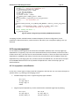
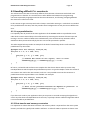
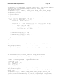
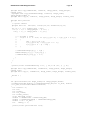
After annotating the code in this manner, we run the GPSMETranslator executable as shown in
Section 2.3 Using the command-line options. In case we target CUDA, the output will be the
following:
A *.cu CUDA file that contains:
o
The transformed kernel - This function will be compiled with the device compiler
and executed on the GPU.
o
The host-code. This code will issue all the commands to the runtime system. It will
issue memory allocation, memory copying, kernel launches, as well as other
commands to the device.
An example of the output from the GPSME toolkit is outlined in the figures below:
Page 17
GPUtilisation Toolkit Design Document
Unew = alloc3D((n + 2),(m + 2),(k + 2));
Uold = alloc3D((n + 2),(m + 2),(k + 2));
init(Unew,(n + 2),(m + 2),(k + 2));
init(Uold,(n + 2),(m + 2),(k + 2));
int T = 20;
int nIters = 0;
double time_elapsed;
double Gflops = 0.0;
/* Mint: Replaced Pragma: #pragma mint copy( Uold, toDevice,( n + 2 ),( m + 2
),( k + 2 ) ) */
cudaError_t stat_dev_1_Uold;
cudaExtent ext_dev_1_Uold = make_cudaExtent(((n+2)) * sizeof(double
),((m+2)),((k+2)));
/* Mint: Malloc on the device */
cudaPitchedPtr dev_1_Uold;
stat_dev_1_Uold = cudaMalloc3D(&dev_1_Uold,ext_dev_1_Uold);
if (stat_dev_1_Uold != cudaSuccess)
fprintf(stderr,"%s\n",cudaGetErrorString(stat_dev_1_Uold));
/* Mint: Copy host to device */
cudaMemcpy3DParms param_1_dev_1_Uold = {0};
param_1_dev_1_Uold.srcPtr = make_cudaPitchedPtr(((void *)Uold[0][0]),((n+2))
* sizeof(double ),((n+2)),((m+2)));
param_1_dev_1_Uold.dstPtr = dev_1_Uold;
param_1_dev_1_Uold.extent = ext_dev_1_Uold;
param_1_dev_1_Uold.kind = cudaMemcpyHostToDevice;
stat_dev_1_Uold = cudaMemcpy3D(¶m_1_dev_1_Uold);
…………………….
#pragma mint for nest ( all ) tile ( 16, 16, 16 ) chunksize ( 1, 1, 16 )
int num3blockDim_1_1527 = (k - 1 + 1) % 16 == 0?(k - 1 + 1) / 16 : (k 1 + 1) / 16 + 1;
int num2blockDim_1_1527 = (m - 1 + 1) % 16 == 0?(m - 1 + 1) / 16 : (m 1 + 1) / 16 + 1;
int num1blockDim_1_1527 = (n - 1 + 1) % 16 == 0?(n - 1 + 1) / 16 : (n 1 + 1) / 16 + 1;
float invYnumblockDim_1_1527 = 1.00000F / num2blockDim_1_1527;
dim3 blockDim_1_1527(16,16,1);
dim3
gridDim_1_1527(num1blockDim_1_1527,num2blockDim_1_1527*num3blockDim_1_1527);
mint_1_1527<<<gridDim_1_1527,blockDim_1_1527>>>(n,m,k,c0,c1,dev_2_Unew,dev_1_U
old,num2blockDim_1_1527,invYnumblockDim_1_1527);
cudaThreadSynchronize();
cudaError_t err_mint_1_1527 = cudaGetLastError();
Figure 3: GPSME generated host code
GPUtilisation Toolkit Design Document
Page 18
__global__ void mint_1_1527(int n,int m,int k,double c0,double
c1,cudaPitchedPtr dev_2_Unew,cudaPitchedPtr dev_1_Uold,int
num2blockDim_1_1527,float invYnumblockDim_1_1527)
{
double *Unew = (double *)dev_2_Unew.ptr;
int _width = dev_2_Unew.pitch / sizeof(double );
int _slice = dev_2_Unew.ysize * _width;
double *Uold = (double *)dev_1_Uold.ptr;
float blocksInY = num2blockDim_1_1527;
float invBlocksInY = invYnumblockDim_1_1527;
int _p_x;
int _p_y;
int _p_z;
{
int _upperb_y = m;
int _upperb_x = n;
int _idx = threadIdx.x + 1;
int _gidx = _idx + blockDim.x * blockIdx.x;
int _idy = threadIdx.y + 1;
int _gidy = _idy + blockDim.y * 1 * blockIdx.y;
int _idz = threadIdx.z + 1;
int blockIdxz = blockIdx.y * invBlocksInY;
int blockIdxy = blockIdx.y - blockIdxz * blocksInY;
_gidy = _idy + blockIdxy * blockDim.y;
int _gidz = _idz + blockIdxz * 16;
int _index3D = _gidx + _gidy * _width + _gidz * _slice;
{
int _upper_gidz = _gidz + 16 < k?_gidz + 15 : k;
{
if (_gidy >= 1 && _gidy <= m) {{
if (_gidx >= 1 && _gidx <= n)
for (_gidz = _gidz; _gidz <= _upper_gidz; _gidz += 1) {
_index3D = _gidx + _gidy * _width + _gidz * _slice;
{
Unew[_index3D] = ((c0 * Uold[_index3D]) + (c1 *
(((((Uold[_index3D - 1] + Uold[_index3D + 1]) + Uold[_index3D - _width]) +
Uold[_index3D + _width]) + Uold[_index3D - _slice]) + Uold[_index3D +
_slice])));
}
}
}
}
}
}
}
}
GPUtilisation Toolkit Design Document
Page 19
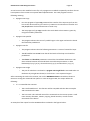
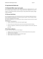
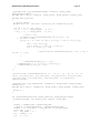
3.2 SME code working example
In this section a sample code from one of the SME partners in the project is presented. As can be
seen also from this sample, the effort necessary to annotate the code is much less than the effort
needed to write an optimal parallel implementation. As can be seen in the input source code from
Figure 5, in order to pass through the toolkit, the third dimension of the arrays has to be “artificially
created”. Other samples of code can also be transformed in this manner.
int getartiblocks(int image_width,int image_height,double
***imDenoised_GPU,double ***oneChannelImage_GPU,int fv_size, double
***fv_GPU,int intraBlockRelativeOffset)
{
int counter = 0;
int row;
int column;
int row_offset;
int column_offset;
float denoised_value;
double ***imDenoised = imDenoised_GPU;
double ***oneChannelImage = oneChannelImage_GPU;
double ***fv = fv_GPU;
int
index_z = 1;
#pragma mint copy(imDenoised, toDevice, index_z, image_width, image_height)
#pragma mint copy(oneChannelImage, toDevice, index_z, image_width,
image_height)
#pragma mint copy(fv, toDevice, index_z, index_z, fv_size)
#pragma mint parallel
{
#pragma mint for nest(all) tile(16,16,16) chunksize(1,1,16)
for (int j = 1 ; j <=1 ; j++){
for (int t = 1 ; t <=1 ; t++){
for (int i = 0; i < (image_height * image_width); i++) {
row = (i / image_width);
column = (i % image_width);
row_offset = (row % 8);
column_offset = (column % 8);
if ((((row_offset >= intraBlockRelativeOffset) && (row_offset <= ((8 intraBlockRelativeOffset) - 1))) && (column_offset >=
intraBlockRelativeOffset)) && (column_offset <= ((8 intraBlockRelativeOffset) - 1))) {
denoised_value = imDenoised[0][row][column];
fv[0][0][counter++] = (oneChannelImage[0][row][column] denoised_value);
}
}
}
}
}
#pragma mint copy(imDenoised, fromDevice, index_z, image_width, image_height)
#pragma mint copy(oneChannelImage, fromDevice, index_z, image_width,
image_height)
#pragma mint copy(fv, fromDevice, index_z, index_z, fv_size)
return 1 ;
}
Figure 5: SME code passing through GPSME toolkit
GPUtilisation Toolkit Design Document
Page 20
3.3 Example Makefile for multi-file support
Until this example, we have only used a single source file for input to the GPSME toolkit. However,
one Makefile is provided below as a basis for creating C++ multi-file projects by the users of the tool:
#Input/outputs
SOURCES=MemoryManagement.cpp Timings.cpp Poisson19.cpp Heat3D.cpp main.cpp
CPU_EXECUTABLE=MultiCpp_cpu
GPU_EXECUTABLE=MultiCpp_gpu
#Compiler settings
CC=g++
CFLAGS=-c -Wall
LDFLAGS=
#Generated variables
OBJECTS=$(SOURCES:.cpp=.o)
TEMP=$(basename $(SOURCES))
TEMP2=$(addprefix gpsme_, $(TEMP))
CUDASRCS=$(addsuffix .cu, $(TEMP2))
CUDAOBJS=$(CUDASRCS:.cu=.o)
# Stops make deleting the intermediate (.cu) files after compiling them.
# http://darrendev.blogspot.nl/2008/06/stopping-make-delete-intermediatefiles.html
.SECONDARY:
#Default target
all: gpu cpu
#Target for CPU version
cpu: $(SOURCES) $(CPU_EXECUTABLE)
$(CPU_EXECUTABLE): $(OBJECTS)
$(CC) $(LDFLAGS) $(OBJECTS) -o $@
#Taget for GPU version
gpu: $(SOURCES) $(GPU_EXECUTABLE)
$(GPU_EXECUTABLE): $(CUDAOBJS)
nvcc $(CUDAOBJS) -o $@
%.o : %.cu
nvcc -c $< -o $@
gpsme_%.cu : %.cpp
GPSMETranslator $< -o $@
clean:
#rm -rf $(OBJECTS) $(CUDAOBJS) $(CPU_EXECUTABLE) $(GPU_EXECUTABLE)
$(CUDASRCS) $(ROSEFILES)
rm -rf $(CPU_EXECUTABLE)
rm -rf $(GPU_EXECUTABLE)
rm -rf a.out
rm -rf gpsme_*
When calling make in the directory in which the Makefile resides, two versions will be created, one
for the CPU, and a different CUDA one for the GPU. In the case of the GPU one, the GPSMETranslator
is firstly called to translate the annotated input files to CUDA. Then, the NVIDIA compiler nvcc is used
GPUtilisation Toolkit Design Document
Page 21
to compile the *.cu generated file to a *.o object file. Finally, after this process is repeated for all the
input files, nvcc is again invoked in order to link all the object files together and create the GPU
executable. For the CPU version, the input files are compiled directly with the g++ UNIX C++ compiler.
This script was provided as a model, and can be further extended to provide compile options specific
to OpenCL.
GPUtilisation Toolkit Design Document
Page 22
4. Detailed Design
Technically, GPSME features techniques to adapt automatic parallelization to the latest GPU
compute architecture to deliver optimal performance. This is expected to greatly improve on
traditional CPU-based automatic parallelization. The literature review has suggested that the
techniques in this area are still very much in their infancy and that there is no existing toolkit that
can benefit the SMEs immediately.
Among others, the product shall support:
Automatic parallelization under Linux natively and under other OS through the use of a webservice;
C++ programming language;
Parallelization of all parallelizable types of loops in the code;
Specific semi-automated directives/clauses (like OpenMP).
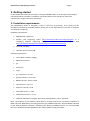
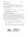
4.1 System and execution model
The system structure and translation flow of the GPSME toolkit is illustrated in Figure 1. The input to
the toolkit is C/C++ source code annotated with GPSME pragmas. Once the source file is read, the
ROSE frontend constructs the AST and passes it to the core of the GPSME toolkit. The core of the
toolkit traverses the AST and queries the parallel regions containing data-parallel for-loops.
Directives in a parallel region go through the components of the identifier, analyser and optimizer in
the toolkit core. The translator component uses the conducted rules from the above components to
transform the AST. The output from the toolkit is CUDA/OpenCL source code generated by unparsing
the transformed AST. The GPSME-generated source file follows the CUDA (OpenCL is similar) system
assumptions as seen in Figure 6. These assumptions are as follows:
The host (CPU) has a different address space from the device (GPU) address space.
The host is typically a multi-core CPU, coupled to the system main memory.
The device is typically a many-core GPU with a complex memory hierarchy and with at least
two levels of parallelism.
The host issues commands and data to the device. The execution of a kernel takes place on
the device, and the host reads back the results by again issuing a command to the device.
.
Figure 6: Mint system model
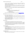
GPUtilisation Toolkit Design Document
Page 23
Figure 7: Mint execution model
4.2 GPSME Pragmas
The design of the toolkit starts from the defined user annotations. GPSME has inherited a set of 5
pragmas from the Mint project. This minimal set of pragmas will be extended during the course of
the project, with some more specialized pragmas that will have the role of fine-tuning the code
transformation process (e.g. improving the memory management).
#pragma mint parallel [clauses]: indicates the start of a structured block of code
representing the region containing parallel work. This region implies the use of a different
address space (device address space) and creates an accelerator scope for the variables.
These regions will be accelerated. Before control enters the parallel region, any data used in
the region must have previously been transferred using the copy directive. It is the
programmer’s responsibility to specify the variable names, the size and the number of
dimensions in case of a copy. This should be provided by the prior use of a #pragma copy
directive. Currently, it is not supported to have a parallel region nested inside another
parallel region.
#pragma mint for [clauses]: marks the succeeding for-loop for GPU acceleration and
manages data decomposition and work assignment. Each such parallel for-loop becomes a
CUDA or OpenCL kernel. After the kernel returns, there is an implicit barrier, synchronizing
all the device threads to the host thread. This is the most powerful annotation, having also a
few clauses that extend its capabilities:
o
nest(#|all): indicates the depth of for-loop parallelization within a loop nest. It can
be an integer or it can be all to specify that all the loops from within the loop nest
are parallelizable. If the nest clause is omitted, only the outer-most for-loop is
parallelized.
GPUtilisation Toolkit Design Document
Page 24
o
tile(tx,ty,tz): specifies how the iteration space of a loop nest is to be subdivided into
tiles. A data tile is a group of threads. In particular for the NVIDIA notation, a tile
corresponds to the number of data points computed by a thread block.
o chunksize(cx,cy,cz): aggregates logical threads into a single CUDA or OpenCL thread.
For some applications, if each point is calculated by a device thread, the workload
for each thread is not sufficient to obtain high performance. For this kind of
applications, the granularity of the separation of work into threads is controlled
using this clause. Together with the tile clause, the chunksize clause specifies the
number of threads residing in a thread clock. This number is
threads(tx/cx,ty/cy,tz/cz).
#pragma mint copy (src|dst, toDevice|fromDevice,*Nx,Ny,Nz,…+): expresses data transfers
between the host and device. The programmer should manually handle all the transfers
to/from device memory using this pragma. Users should be careful when needing data back
from the device. At the exit from a parallel region, the data on the device is destroyed, and
thus has to be read with a copy directive. The specific modifiers of this pragma are:
o src|dst is the variable name that should be transferred.
o toDevice|fromDevice represents the direction of the data copy.
o *Nx,Ny,Nz,…+ represent the dimension of the array from the fastest to slowest
varying dimension.
#pragma mint barrier: synchronizes all the threads.
#pragma mint single: indicates serial regions. Depending on the requirements, either a host
or a single device thread executes the region.
4.2.1 New pragmas
The pragmas listed above have been inherited from the Mint project, but in addition to these we
have defined some new pragmas to help with different code structures such as those found in the
code from IME. These pragmas particularly aim at solving 2D image processing problem. Before
using these pragmas, it is necessary to revise CPU code into an acceptable format of auto-processing
CPU code. It assumes that the 2D Image data is stored into a 2D float pointer : Image[width][height],
and a known size window would be created into a 1D array to process some operations in this image,
such as median filter, sobel filter, etc.
Therefore, the general steps of 2D image processing operations are below:
1. To define the required 1D array before traveling the image data stored in 2D float pointer.
2. For each selected window, to transfer the relevant image data in buffer to the 1D array.
3. To do any necessary image processing operations on this 1D array.
4. To find the required value into 1D array and assign to image data.
In order to achieve these steps, four pragmas are designed in GPSME toolkit:
#pragma GPSME single remaininloop
This pragma is used to put the definition statement of 1D array into CUDA kernels. It is because in
revised CPU code, the definition statement of 1D array usually is putted outside the “for” Loop, but
in CUDA kernel, it should be defined inside the kernel. This pragma is to put the definition statement
GPUtilisation Toolkit Design Document
Page 25
from outside “for” loop into inside “for” loop. Ideally, it would be not limited the number of 1D or 2D
arrays are defined, in IME case, one 1D array is required.
#pragma GPSME single transfer
This pragma is used to parse the codes of transferring image data from buffer into 1D array in CUDA
kernel. One code transferring is on the initialization, condition statement and increment of “for”
loop during the traveling image data. Another code transferring is on replacing 2D pointer image
buffer on host by CUDA Texture Array on device. The thread calculation process should be generated
at the beginning of CUDA kernel.
#pragma GPSME single remain
This pragma is used to remain the codes of operating 1D array in CPU code as same as in CUDA
kernel. It requires the codes in this pragma are variable-independent; the referenced 1D or 2D arrays
should be already defined into GPSME single remaininloop pragma. Meanwhile, the operations in
the code should be simple calculation and suitable for GPU threads.
#pragma GPSME single assign
This pragma is used to parse the codes of transferring image data from 1D array into texture buffer
in CUDA kernel. Code transferring is on replacing 2D pointer image buffer on host by CUDA Texture
Array on device. The thread calculation process should be generated at the beginning of CUDA
kernel.
4.3 Input languages
In this section the input possibilities of the GPSME toolkit are presented. Initially, Mint supported
only C annotated code. After some modifications to the front-end, now C++ code can pass through
the toolkit. The parallel loop can now be in member functions, so the code palette that can pass
through the toolkit is further extended. However, not all C++ OOP constructs are supported. Inside
of the parallel constructs delimited by the pragmas, there are also some limitations. These will be
discussed in section 5.2 Known limitations, and some of them will be resolved in further revisions.
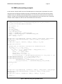
4.4 Output languages
Initially, Mint had support for the CUDA backend. Because this is a project involving multiple SMEs,
each one with its particular GPU in mind, the palette of output languages had to be extended. The
current version of the GPSME toolkit offers an OpenCL backend, increasing the use of the toolkit to
platforms like AMD or Intel.
Below is the most important information about the OpenCL backend.
Page 26
GPUtilisation Toolkit Design Document
/* Mint_num_platforms: Device Configuration. */
printf("------ Start to get PlatformIDs \n");
cl_platform_id platform_id = (NULL);
cl_device_id device_id = (NULL);
cl_uint ret_num_devices;
cl_uint ret_num_platforms;
cl_int ret;
cl_context context = (NULL);
cl_command_queue command_queue = (NULL);
ret =
clGetPlatformIDs(1,&platform_id,&ret_num_platforms);
printf("------ Get PlatformIDs \n");
ret =
clGetDeviceIDs(platform_id,CL_DEVICE_TYPE_DEFAULT,1,&device_id,&ret_num_platfor
ms);
context = clCreateContext((NULL),1,&device_id,(NULL),(NULL),&ret);
printf("------ Start Loading the kernel .cl file \n");
/* Mint: Loading the kernel. */
cl_program program;
Figure a8: program
OpenCL configuration
generated
by GPSME
OpenCL backend
/* Mint: Create
from the kernel
source.
*/
printf("------ Create Program With Source file \n");
program = clCreateProgramWithSource(context,1,((const char
)(&source_str)),((const size_t * )
mapping**
has
been realized between CUDA and OpenCL for device configuration, kernel
(&source_size)),&ret);
A
parameters, allocate structures, create structures and others, but a complete mapping is not yet
Mint: Build the program. */
achieved. /*cl_kernel
kernel;
printf("------ Create Kernel file \n");
/* Mint: Create the OpenCL kernel. */
kernel = clCreateKernel(program,"heat_3D",&ret);
ret = clBuildProgram(program,1,&device_id,(NULL),(NULL),(NULL));
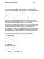
4.5 Loop management
For the majority
of the algorithms
encountered in the SMEs codebase, there are only slight loop
command_queue
= clCreateCommandQueue(context,device_id,0,&ret);
dependencies. So typically, loop nests are transformed directly to kernel bodies, and a kernel call is
issued instead. This is also the case for stencil methods. However, if there are some loops that have
dependencies, GPSME has the ability to use the Loop Transformation API from ROSE, remove the
dependencies by rearranging the AST, and then rewrite the modified AST. This will assure the input
to the GPSME toolkit will be as free as possible of dependencies. Some of the loop types are
described below.
4.5.1 Loop pattern classification
In this class, several types of loops would be recognized, and then we can use some techniques to
optimize them, e.g. skewing, interchanging, stencil.
Standard Single Loop: This is a typical singe loop type as below:
do I = 0, N
S1 : A(I) = B(I) + 1
S2: C(I) = A(I) + 1
enddo
Single Loop with dependency: can be transformed to standard single loop by skewing
do I = 0, N
S1 : A(I) = B(I) + 1
S2: C(I) = A(I-1) + 1
do I = 0, N
S1 : A(I) = B(I) + 1
S2: C(I) = A(I+1) + 1
Page 27
GPUtilisation Toolkit Design Document
enddo
enddo
Standard Double Loop: This is a typical double loop type as below:
do I = 0, N
do I = 1, N
do J = 0, M
do J = 1, M
S1 : A(I,J) = F(B(I,J) )
S1 : A(I,J) = F((I-1,J) )
enddo
enddo
enddo
enddo
Double Loop with dependencies: can be transferred to standard double loop by
interchanging
Do I = 1, N
Do J = 1, M
S1 : A(J,I) = F(B(J-1,I))
Enddo
Enddo
Do I = 1, N
Do J = 1, M
S1 : A(I,J) = F(B(I-1,J) )
Enddo
Enddo
do I = 1, N
do J = 1, M
S1 : A(J,I) = F(B(J-1,I-1))
enddo
enddo
do I = 0, N
do J = 0, 1
S1 : A(I,J) = F(B(I-1,J+1) )
enddo
enddo
do I = 0, 1
do J = 0, M
S1 : A(J,1-I) = F(B(J-1,1-I+1))
enddo
enddo
Standard Three Loops: There is a typical triple loop type as below:
do I = 0, N
do J = 0, M
do T = 0, K
S1 : A(I,J,K) = F(B(I,J,K) )
enddo
enddo
enddo
The stencil computing technique can solve the more complex three nested loops.
The identification of these loops uses Data Dependency Analysis (DDA) techniques. We will use the
functions provided by ROSE to traverse the parallel regions of the AST, and then classify the type of
the loop. In order to reach this aim, some data has to be collected:
Number of Loops: Number of “For” nodes in the AST.
Loop Parameters: parameters used in each “For” loop.
Local Variable: variable defined in the loop bodies.
Reference Variable: variable used in the loop bodies.
Note: this sub-component is under further investigation.
GPUtilisation Toolkit Design Document
Page 28
4.6 Memory management
The memory management mechanisms are triggered by the #pragma copy pragmas present in the
user code. First, the array is created on the target device, and afterwards the data is copied from the
source to the specified target destination. All the allocation and copying is made through the CUDA
and OpenCL runtime. However, this pragma should be extended in order to select between creation
and copying. Maybe the data is already on the device, and it doesn’t make sense to create/allocate it
again. This could also facilitate the data persistence on the device between subsequent kernel calls,
hence improving performance. It is known that the biggest problem in GPGPU computing is the lowspeed PCIe copies between host and device.
GPUtilisation Toolkit Design Document
Page 29
5. Implemented features
5.1 Extended Mint’s input and output
In this initial version of the toolkit, the main addition to Mint was the added support for C++ input
files, and added support for OpenCL output. This greatly extends the capabilities of this research
initiative, increasing the possibility of experimenting with a big codebase while targeting a bigger
number of platforms.
5.2 Known limitations
One of the biggest limitations we have determined so far when working with SME code in Mint is
exactly what Mint was designed for: it is a domain-specific translator. It works and gives the best
results when targeting 3D stencil methods.
Also, memory management is a bit limiting at this moment, making unnecessary copies for specific
algorithmic cases.
The following is a list of limitations:
Unable to parallelize function calls inside of parallel regions.
Cannot work on other domains (only 3D stencil-based methods) without tweaking.
Memory management is inefficient for given types of algorithms. Extra memory copies are
generated.
5.3 In future releases
In order to reach these objectives, the test strategy is:
Adding more execution patterns that can be detected, besides the 3D stencil-pattern
Improve memory management
Improve support for function calls inside parallel regions
Improve support for pointer arithmetic
GPUtilisation Toolkit Design Document
Page 30
6. Writing code for parallelisation
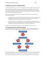
Automatic parallelisation of source code is a complex process and the GPSME toolkit needs a good
understanding of the code which is being converted. Ideally the toolkit would be able to handle
arbitrary C++ code as input, but the state-of-the-art in automatic parallelisation is still a long way
from this goal. Therefore, the purpose of this section is to guide the user on how to best write code
which can be parallelised by the GPSME toolkit.
There are two fundamental limitations which must be kept in mind when writing code to be
processed by the toolkit:
1. The GPSME toolkit is a source-to-source translator, which means it needs the source code to
the algorithm being parallelised. This prohibits the use of external libraries to which the
toolkit cannot see the source code when conversion is performed.
2. Not all constructs which can be expressed in C++ can be translated to GPU equivalents. In
particular the regions to be parallelised should be simple nested loops which do not contain
interdependencies, complex conditional logic, or most types of function call.
Guidelines for dealing with these limitations are further discussed in the sections below.
6.1 Dealing with external dependencies
When trying to understand the behaviour of the toolkit with regard to external dependencies it is
useful to have a basic understanding of the parallelisation process. The process is as follows:
The input to the toolkit is C++ source code, and the output is also source code (C++/OpenCL/CUDA)
with transformations applied. Internally the toolkit builds an abstract syntax tree from the source
code, applies parallelising transformations to this, and then generates the corresponding output
GPUtilisation Toolkit Design Document
Page 31
source code. It is this need to build an abstract syntax tree which underpins the requirement to have
the source code to parts of the algorithm which are being parallelised.
Of course, most applications do have some form of external dependencies as software reuse is a
strong principle of good engineering. To some degree it is indeed possible to parallelise such
applications if the code can be revised according to the guidelines below.
6.1.1 Working with the toolkit locally
Using the toolkit locally under Linux offers the most flexibility as it is possible to configure the host to
have the required dependencies installed, and this can ease the code revising process. However you
should watch out for the following scenarios.
Let’s say you have an application which you wish to parallelise but which makes use of the OpenCV
toolkit for image processing operations. You might have a nested for loop which contains a call to an
OpenCV function:
#pragma mint for nest(2) tile(16,16)
for(int x = 0; x < 128; x++)
{
for(int y = 0; y < 128; y++)
{
.
.
// External function call
cvSomeFunction();
.
.
}
}
In this case the code is not suitable for parallelisation because the function ‘cvSomeFunction()’ is
contained within a shared library (.dll or .so) and is implemented in CPU machine code. It is not
possible to move this function to the GPU because GPUs have a different instruction set and
architecture.
In this case the only option is to remove the call to cvSomeFunction() and replace it with your own
implementation, but only if you believe that the algorithm being implemented matches the parallel
nature of the GPU.
Another important example is when dependencies are outside the region being parallelised but
within the same source file. Consider the case when we have a call to a Windows system function
before the nested loop:
#include <windows.h>
.
.
.
someWindowsFunction();
.
.
.
GPUtilisation Toolkit Design Document
Page 32
#pragma mint for nest(2) tile(16,16)
for(int x = 0; x < 128; x++)
{
for(int y = 0; y < 128; y++)
{
.
.
.
}
}
Because the toolkit runs on Linux the use of Windows functions (even just including ‘windows.h’)
represents an external dependency. The GPSME translator is unable to see the definitions of these
Windows functions and so is not able to build the abstract syntax tree. Fortunately in this case it is
possible to work around the limitation by splitting the code to be parallelised into a separate file and
only running the GPSME toolkit on that:
// In „parallelisable.cpp‟ (for example)
#pragma mint for nest(2) tile(16,16)
for(int x = 0; x < 128; x++)
{
for(int y = 0; y < 128; y++)
{
.
.
.
}
}
//In main.cpp
#include <windows.h>
#include “parallelisable.h”
.
.
someWindowsFunction();
.
.
//Now call parallelised function in parallelisable.cpp
With this approach the GPSME toolkit never sees the code which it can’t handle and so
parallelisation is possible.
6.1.2 Working with the remote server
Driven by the potential difficulties of having a local GPSME installation, and also to increase the
visibility of the toolkit, we include access to the toolkit through a remote web server. The web server
can be accessed at http://gp-sme.co.uk/web_face/.
This service facilitates the translation of the user source code, not needing anything related to the
toolkit locally installed on the users’ machines. A screenshot from the online translator is given in the
image below.
GPUtilisation Toolkit Design Document
Page 33
The typical usage of the GPSME web application is as follows:
The user creates and account with their details.
The user uploads a C/C++ file
The users upload the necessary header files.
The user selects the desired output type.
The user initiates the code translation process.
It takes a few seconds for the GPSME remote server to process the user files.
The results can be retrieved under the ‘Processed files’ tab.
Many users will not be running the toolkit locally on a Linux machine but will instead be making use
this remote web server. In this case you should keep the following points in mind in addition to
those raised previously:
If you have an external dependency then it must be installed on the remote webserver in
addition to your local machine. You will need to contact you server administrator to get this
set up.
When uploading a C++ file for parallelisation you must also upload any of your own headers
on which the C++ file is dependant. It is assumed that these belong in the same directory as
the C++ source file, so avoid paths in your #include statements.
The webserver can also be installed locally on SME servers and act as a demo for the eventual
customers.
GPUtilisation Toolkit Design Document
Page 34
6.2 Handling difficult C++ constructs
The architecture of the GPU is inherently different from the CPU architectures with which most
programmers are familiar. As a result there are often differences between the programming
constructs exposed by languages aimed at the two architectures, and forming a mapping between
the constructs is often non-trivial.
In this section we give some tips and tricks to keep in mind when writing C++ code which is intended
to be parallelised for the GPU, and also provides some background as to why the various differences
exist.
6.2.1 Loop parallelisation
It is hopefully clear by now that the main application of the GPSME toolkit is to parallelise source
code which contains nested loops. The toolkit works by extracting the contents of these loops and
running it across a number of GPU cores simultaneously. This means that loop iterations which
would have been processed serially by the CPU can now be processed in parallel.
The code snippet below provides an example of the kind of nested loop which is well suited for
parallelisation by the toolkit:
#pragma mint for nest(2) tile(16,16)
for(int x = 0; x < 128; x++)
{
for(int y = 0; y < 128; y++)
{
// Double the value of all inputs, this is fine.
someArray[x][y] = someArray[x][y] * 2.0f;
}
}
Of course, real world code is often more complex than that shown above and may contain loop
interdependencies which impede the parallelisation process. A typical example is when the results of
one iteration are used in the next iteration, and so it is not possible to execute the iterations in
parallel because the required data is not available. For example:
#pragma mint for nest(2) tile(16,16)
for(int x = 0; x < 128; x++)
{
for(int y = 0; y < 128; y++)
{
// This is not possible because we depend on previous „x‟
someArray[x][y] = someArray[x-1][y] * 2.0f;
}
}
If you have such code in your application then you may want to consider rewriting the algorithm in
such a way that these interdependencies do not exist, or perhaps choose a different algorithm which
is more amicable to parallelisation.
6.2.2 Data transfer and memory constraints
It is important to realise that GPUs have their own memory which is separate from the main system
memory and which is typically both smaller and faster. In order for GPUs to operate on data it must
GPUtilisation Toolkit Design Document
Page 35
first be transferred into GPU memory using the #pragma mint copy directive already discussed,
and the results must be transferred back to the main system memory after the transfer is complete.
This architecture has a significant effect on the kinds of algorithms which can be moved to the GPU
and on the benefit obtained by doing so. In particular you should keep the following points in mind:
Bandwidth: There is a limit to the rate at which data can be transferred to the GPU and back
again, and this limit varies between system. Typically the rate at which data can be sent to
the GPU is higher than the rate at which it can be retrieved. If an application does not do
significant work on each piece of data then it is possible for the application to be limited by
this rate of data transfer, and so a significant speedup might not be obtained.
Latency: Each time a data transfer is requested there is a small delay before it actually
occurs. If an application is performing a lot of small transfers between the GPU and system
memory then these accumulated delays can have a noticeable effect on the speed of the
application. In general it is better to perform a single large data transfer rather than several
small ones.
Memory size: The amount of memory available on a GPU can vary from approx. 128Mb up
to 2Gb, but it is always significantly less than the available system memory. You should also
be aware that some memory is already taken up for purposes such as holding the frame
buffer which is used during rendering. With this in mind, you may want to optimise your
algorithm to work on smaller amount if data, for example by braking large images down into
a number of tiles (which also has cache benefits).
6.2.3 Conditional logic
GPUs utilise a Single Instruction Multiple Data (SIMD) pipeline in order to effectively achieve
parallelism. Execution of programs is performed by a large number of threads which each operate on
a separate piece of the data set. Due to the architecture of GPUs it is important for all threads to be
executing the same instruction at the same time.
This architecture can be problematic for algorithms which contain conditional branches. While valid,
these branches do not map well to the GPU architecture because they can cause the threads to
exhibit divergent behaviour. Consider the following example:
#pragma mint for nest(2) tile(16,16)
for(int x = 0; x < 128; x++)
{
for(int y = 0; y < 128; y++)
{
float val = someArray[x][y];
if(val < 0.001f)
{
continue; // Optimisation
}
else
{
.
. // Some expensive code here
.
GPUtilisation Toolkit Design Document
Page 36
}
}
}
In this code the conditional test ‘if(val < 0.001f)’ has been added as an intended optimisation
because it skips the expensive code for certain values of ‘val’. However, on the GPU this optimisation
does not work as expected because all threads must take the same path and so threads cannot
return early. Instead the execution time for a group of threads is determined by the slowest thread
in that group.
6.2.5 Function calls
Function calls are one of the fundamental building blocks of C/C++ programs, but their
implementation in GPU languages such as CUDA or OpenCL is different to what might be expected.
In a modern CPU function calls are implemented by saving the current program state onto the stack
and then using a ‘jump’ instruction which transfers execution of a program from one point to
another. This approach does not match the architecture of GPUs (for similar reasons to the issues
with conditional logic) and so current GPUs do not support jumps or function calls.
That said, programming languages such as OpenCL and CUDA do allow functions to be defined and
called from the main kernel but a different implementation is used. In particular the function call is
actually inlined into the function that called it. This is done during the compilation stage.
The impact of this on the GPSME toolkit is that parallel regions can include function calls provided
that those functions can be inlined by the compiler. This requires a definition of the function to be
available to be available to the toolkit at the time it processes the callsite. Functions definitions
should not exist in external libraries or separate compilation units.
As a concrete example the following code will give difficulties to the GPSME toolkit:
// In functions.h
float addOne(float val);
// In functions.cpp
#include “functions.h"
float addOne(float val)
{
return val + 1.0f;
}
// In main.cpp
#include “functions.h"
.
.
.
#pragma mint for nest(2) tile(16,16)
for(int x = 0; x < 128; x++)
{
for(int y = 0; y < 128; y++)
{
GPUtilisation Toolkit Design Document
Page 37
// ERROR: No definition for addOne()
float result = addOne(someArray[x][y]);
}
}
But these difficulties can be resolved by rearranging the code as follows:
// In main.cpp
float addOne(float val)
{
return val + 1.0f;
}
.
.
.
#pragma mint for nest(2) tile(16,16)
for(int x = 0; x < 128; x++)
{
for(int y = 0; y < 128; y++)
{
// OK: addOne() is in this compilation unit.
float result = addOne(someArray[x][y]);
}
}
A related problem is recursion because a recursive function cannot be inlined (at least not if the
termination a criterion is being determined at runtime). For this reason it is not possible to
parallelise regions containing recursive function calls.
GPUtilisation Toolkit Design Document
Page 38
Appendix A. GPSME programs
/*
by Didem Unat
3D 7-point jacobi
Written to be used as an input program to mint translator
*/
//#include "common.h"
#include <stdio.h>
#include <math.h>
#include <omp.h>
#include <stdlib.h>
#include <assert.h>
#include <sys/time.h>
#define REAL double
#define FLOPS 8
#define chunk 64
const double kMicro = 1.0e-6;
REAL ***alloc3D(int n, int m,int k)
{
REAL ***m_buffer=NULL;
int nx=n, ny=m, nk = k;
m_buffer = (REAL***)malloc(sizeof(REAL**)* nk);
assert(m_buffer);
REAL** m_tempzy = (REAL**)malloc(sizeof(REAL*)* nk * ny);
REAL *m_tempzyx = (REAL*)malloc(sizeof(REAL)* nx * ny * nk );
int z, y;
for ( z = 0 ; z < nk ; z++, m_tempzy += ny ) {
m_buffer[z] = m_tempzy;
for ( y = 0 ; y < ny ; y++, m_tempzyx += nx ) {
m_buffer[z][y] = m_tempzyx;
}
}
return m_buffer;
}
double getTime()
{
struct timeval TV;
const int RC = gettimeofday(&TV, NULL);
if(RC == -1)
{
printf("ERROR: Bad call to gettimeofday\n");
return(-1);
}
return( ((double)TV.tv_sec) + kMicro * ((double)TV.tv_usec) );
GPUtilisation Toolkit Design Document
}
Page 39
// end getTime()
//allocate 3D array
REAL ***alloc3D_(int n, int m,int k){
REAL ***E=NULL;
int nx=n, ny=m, nk = k;
E = (REAL***)malloc(sizeof(REAL**)* nk);
assert(E);
E[0] = (REAL**)malloc(sizeof(REAL*)* nk * ny);
E[0][0] = (REAL*)malloc(sizeof(REAL)*nx * ny * nk );
int jj,kk;
for(kk=0 ; kk < nk ; kk++){
if(kk > 0)
{
E[kk] = E[kk-1] + ny ;
E[kk][0] = E[kk-1][0] + ny*nx ;
}
for(jj=1; jj< ny; jj++) {
E[kk][jj] = E[kk][jj-1] + nx ;
}
}
return(E);
}
void free3D(REAL*** E)
{
//int k=0;
/* for(k=0 ; k < m ; k++)
{
free(E[k]);
}*/
free(E[0][0]);
free(E[0]);
free(E);
}
void init(REAL*** E, int N, int M, int K)
{
int i,j,k;
for(k=0 ; k < K ; k++)
for(i=0 ; i < M ; i++)
for(j=0 ; j < N ; j++){
E[k][i][j]=1.0;
if(i==0 || i == M-1 || j == 0 || j == N-1 || k==0 || k == K-1 )
E[k][i][j]=0.0;
}
}
//calculate l2norm for comparison
GPUtilisation Toolkit Design Document
Page 40
void calculatel2Norm(REAL*** E, int N, int M, int K, int nIters)
{
int i, j, k =0;
float mx = -1;
float l2norm = 0;
for (k=1; k<= K ; k++){
for (j=1; j<= M; j++){
for (i=1; i<= N; i++) {
l2norm += E[k][j][i]*E[k][j][i];
if (E[k][j][i] > mx)
mx = E[k][j][i];
}
}
}
l2norm /= (float) ((N)*(M)*(K));
l2norm = sqrt(l2norm);
printf(":N %d M %d K %d , iteration %d\n", N, M, K , nIters);
printf(":max: %20.12e, l2norm: %20.12e\n",mx,l2norm);
}
int main (int argc, char* argv[])
{
int n = 256;
int m = 256;
int k = 256;
REAL c0=0.5;
REAL c1=-0.25;
REAL*** Unew; REAL*** Uold;
Unew= alloc3D(n+2, m+2, k+2);
Uold= alloc3D(n+2, m+2, k+2);
init(Unew, n+2, m+2, k+2);
init(Uold, n+2, m+2, k+2);
int T= 20;
printf("\n=====Timings (sec) for 7-Point Jacobi, Solving Heat Eqn ");
if(sizeof(REAL) == 4)
printf(" (Single Precision) =====\n");
if(sizeof(REAL) == 8)
printf(" (Double Precision) =====\n");
printf("Kernel\t Time(sec)\tGflops \tBW-ideal(GB/s)\tBW-algorithm
(N=(%d,%d) ite\
rs=%d)\n", n,n, T);
printf("------\t----------\t--------\t--------------\t------------\n");
int nIters = 0;
double time_elapsed ;
double Gflops=0.0;
#pragma mint copy(Uold, toDevice, (n+2), (m+2), (k+2))
#pragma mint copy(Unew, toDevice, (n+2), m+2, (k+2))
Page 41
GPUtilisation Toolkit Design Document
#pragma mint parallel
{
time_elapsed = getTime();
int t=0;
while( t < T ){
t++;
int x, y, z;
//7-point stencil
#pragma mint for nest(all) tile(16,16,16) chunksize(1,1,16)
for (z=1; z<= k; z++){
for (y=1; y<= m; y++){
for (x=1; x<= n; x++) {
Unew[z][y][x] = c0* Uold[z][y][x] + c1 * (Uold[z][y][x-1] +
Uold[z][y][x+1] +
Uold[z][y-1][x] +
Uold[z][y+1][x] +
Uold[z-1][y][x] +
Uold[z+1][y][x]);
}
}
}
#pragma mint single
{
REAL*** tmp;
tmp = Uold; Uold = Unew; Unew = tmp;
nIters = t ;
}
}//end of while
}//end of parallel region
#pragma mint copy(Uold, fromDevice, (n+2), (m+2), (k+2))
time_elapsed = getTime() - time_elapsed ;
Gflops = (double)(nIters * (n) * (m) * (k) * 1.0e-9 * FLOPS) /
time_elapsed ;
printf("%s%3.3f \t%5.3f\n", "Heat3D
calculatel2Norm(Uold, n, m, k, T);
free3D(Uold);
free3D(Unew);
return 0;
}
Wiener denoising - IME
#include "wiennerdenosing.h"
#include <fstream>
#include <windows.h>
double getTime_2()
{
", time_elapsed, Gflops);
GPUtilisation Toolkit Design Document
Page 42
DWORD t1 ;
t1 = timeGetTime();
return (double)t1 ;
} // end getTime()
double meandenosing(int image_width,int image_height,double
***imDenoised_GPU, double ***oneChannelImage_GPU, int window_size)
{
double ***imDenoised = imDenoised_GPU;
double ***oneChannelImage = oneChannelImage_GPU;
float tmp = 0.0 ;
float win = 1.0/window_size ;
int
max_index = 0 ;
int
index_z = 1;
int
i, j, m ;
double time_elapsed = 0.0 ;
time_elapsed = getTime_2();
#pragma mint copy(imDenoised, toDevice, image_width,
image_height,window_size)
#pragma mint copy(oneChannelImage, toDevice, image_width,
image_height,window_size)
#pragma mint parallel
{
//7-point stencil
#pragma mint for nest(all) tile(16,16,16) chunksize(1,1,16)
//for(int n = 1 ; n < 256 ; n++){
for (m = 1 ; m < window_size - 1; m++){
for (i = 1; i < image_height - 1; i++) {
for(j = 1; j < image_width - 1; j++){
imDenoised[m][i][j] = (oneChannelImage[m][i-1][j-1] +
oneChannelImage[m][i-1][j] + oneChannelImage[m][i-1][j+1] +
oneChannelImage[m][i][j-1] +
oneChannelImage[m][i][j] + oneChannelImage[m][i][j+1] +
oneChannelImage[m][i+1][j-1] +
oneChannelImage[m][i+1][j] + oneChannelImage[m][i+1][j+1])*win
+
(oneChannelImage[m-1][i-1][j-1] + oneChannelImage[m-1][i-1][j] +
oneChannelImage[m-1][i-1][j+1] +
oneChannelImage[m-1][i][j-1] +
oneChannelImage[m-1][i][j] + oneChannelImage[m-1][i][j+1] +
oneChannelImage[m-1][i+1][j-1] +
oneChannelImage[m-1][i+1][j] + oneChannelImage[m-1][i+1][j+1])*win
;
}
}
}
//}
}
#pragma mint copy(imDenoised, fromDevice, image_width,
image_height,window_size)
time_elapsed = getTime_2() - time_elapsed ;
return time_elapsed ;
}
GPUtilisation Toolkit Design Document
Page 43
int getartiblocks(int image_width,int image_height,double
***imDenoised_GPU,double ***oneChannelImage_GPU,int fv_size, double
***fv_GPU,int intraBlockRelativeOffset)
{
int counter = 0;
int row;
int column;
int row_offset;
int column_offset;
float denoised_value;
double ***imDenoised = imDenoised_GPU;
double ***oneChannelImage = oneChannelImage_GPU;
double ***fv = fv_GPU;
int
index_z = 1;
printf("start getartiblocks \n");
#pragma mint copy(imDenoised, toDevice, image_width, image_height,index_z)
#pragma mint copy(oneChannelImage, toDevice, image_width,
image_height,index_z)
#pragma mint copy(fv, toDevice, fv_size, index_z, index_z)
#pragma mint parallel
{
//7-point stencil
#pragma mint for nest(all) tile(16,16,16) chunksize(1,1,16)
for (int j = 1 ; j <=1 ; j++){
for (int t = 1 ; t <=1 ; t++){
for (int i = 0; i < (image_height * image_width); i++) {
row = (i / image_width);
column = (i % image_width);
row_offset = (row % 8);
column_offset = (column % 8);
if ((((row_offset >= intraBlockRelativeOffset) && (row_offset <= ((8 intraBlockRelativeOffset) - 1))) && (column_offset >=
intraBlockRelativeOffset)) && (column_offset <= ((8 intraBlockRelativeOffset) - 1))) {
denoised_value = imDenoised[0][row][column];
fv[0][0][counter++] = (oneChannelImage[0][row][column] denoised_value);
}
}
}
}
}
#pragma mint copy(imDenoised, fromDevice, index_z, image_height,
image_width)
#pragma mint copy(oneChannelImage, fromDevice, index_z, image_height,
image_width)
#pragma mint copy(fv, fromDevice, index_z, index_z, fv_size)
return 1 ;
}
int wiennerdenosing(int image_width,int image_height,double
***oneChannelImage_GPU, int window_size, double ***win_GPU)
{
//double ***imDenoised = imDenoised_GPU;
GPUtilisation Toolkit Design Document
Page 44
double ***oneChannelImage = oneChannelImage_GPU;
double ***v = win_GPU; // win_GPU has to be initlized
float tmp = 0.0 ;
int
max_index = 0 ;
int
index_z = 1;
int
i, j, m ;
//#pragma mint copy(imDenoised, toDevice, image_width,
image_height,index_z)
#pragma mint copy(oneChannelImage, toDevice, image_width,
image_height,index_z)
#pragma mint copy(v, toDevice, window_size, image_width, image_height)
//printf("start wiennerdenosing %d , %d \n", image_height, image_width);
#pragma mint parallel
{
//7-point stencil
#pragma mint for nest(all) tile(16,16,16) chunksize(1,1,16)
for (m = 0 ; m < 1 ; m++){
for (i = 1; i < image_height - 1; i++) {
for(j = 1; j < image_width - 1; j++){
v[i][j][0]
v[i][j][1]
v[i][j][2]
v[i][j][3]
v[i][j][4]
v[i][j][5]
v[i][j][6]
v[i][j][7]
v[i][j][8]
=
=
=
=
=
=
=
=
=
oneChannelImage[m][i-1][j-1];
oneChannelImage[m][i-1][j];
oneChannelImage[m][i-1][j+1];
oneChannelImage[m][i][j-1];
oneChannelImage[m][i][j];
oneChannelImage[m][i][j+1];
oneChannelImage[m][i+1][j-1];
oneChannelImage[m][i+1][j];
oneChannelImage[m][i+1][j+1];
//printf("start wiennerdenosing m %d, i %d, j %d \n", m, i, j);
}
}
}
}
//printf("start wiennerdenosing i %d , j %d, m %d \n", i, j, m);
#pragma mint copy(oneChannelImage, fromDevice, image_width,
image_height,index_z)
#pragma mint copy(v, fromDevice, window_size, image_width, image_height)
return 1 ;
}
int wiennerdenosing2(int image_width,int image_height,double
***imDenoised_GPU, int window_size, double ***win_GPU)
{
double ***imDenoised = imDenoised_GPU;
//double ***oneChannelImage = oneChannelImage_GPU;
double ***v = win_GPU; // win_GPU has to be initlized
float tmp = 0.0 ;
int
max_index = 0 ;
int
index_z = 1;
int
i, j ,m ;
GPUtilisation Toolkit Design Document
Page 45
#pragma mint copy(imDenoised, toDevice, image_width, image_height,index_z)
//#pragma mint copy(oneChannelImage, toDevice, image_width,
image_height,index_z)
#pragma mint copy(v, toDevice, window_size, image_width, image_height)
#pragma mint parallel
{
//7-point stencil
#pragma mint for nest(all) tile(16,16,16) chunksize(1,1,16)
for (i = 1; i < image_height - 1; i++) {
for(j = 1; j < image_width - 1; j++){
for (m = 9 ; m <=90 ; m++){
// To make a order
if((m % 9 >= 9 - m/9) && (v[i][j][m % 9] < v[i][j][m % 9 -1]))
{
tmp = v[i][j][m % 9];
v[i][j][m % 9] = v[i][j][m % 9 - 1];
v[i][j][m % 9 - 1] = tmp ;
}
//oneChannelImage[i][j] = v[4] ;
imDenoised[0][i][j] = v[i][j][4] ;
//imDenoised[0][ii][jj] = 0.5 ;
}
}
}
}
//printf("start wiennerdenosing i %d , j %d, m %d \n", i, j, m);
#pragma mint copy(imDenoised, fromDevice, image_width,
image_height,index_z)
#pragma mint copy(v, fromDevice, window_size, image_width, image_height)
return 1 ;
}
// Fixed the bug
int wiennerdenosing1(int image_width,int image_height,double
***oneChannelImage_GPU, int window_size, double ***win_GPU)
{
//double ***imDenoised = imDenoised_GPU;
double ***oneChannelImage = oneChannelImage_GPU;
double ***v = win_GPU; // win_GPU has to be initlized
float tmp = 0.0 ;
int
max_index = 0 ;
int
index_z = 1;
int
i, j, m ;
//#pragma mint copy(imDenoised, toDevice, image_width,
image_height,index_z)
#pragma mint copy(oneChannelImage, toDevice, image_width, image_height,
window_size)
#pragma mint copy(v, toDevice,image_width, image_height, window_size)
//printf("start wiennerdenosing %d , %d \n", image_height, image_width);
GPUtilisation Toolkit Design Document
Page 46
#pragma mint parallel
{
//7-point stencil
#pragma mint for nest(all) tile(16,16,16) chunksize(1,1,16)
for (m = 0 ; m < window_size ; m++){
for (i = 1; i < image_height - 1; i++) {
for(j = 1; j < image_width - 1; j++){
if(m==0)
v[m][i][j]= oneChannelImage[m][i-1][j-1];
else if(m==1)
v[m][i][j] = oneChannelImage[m][i-1][j];
else if(m==2)
v[m][i][j] = oneChannelImage[m][i-1][j+1];
else if(m==3)
v[m][i][j] = oneChannelImage[m][i][j-1];
else if(m==4)
v[m][i][j] = oneChannelImage[m][i][j];
else if(m==5)
v[m][i][j] = oneChannelImage[m][i][j+1];
else if(m==6)
v[m][i][j] = oneChannelImage[m][i+1][j-1];
else if(m==7)
v[m][i][j] = oneChannelImage[m][i+1][j];
else if(m==8)
v[m][i][j] = oneChannelImage[m][i+1][j+1];
//printf("start wiennerdenosing m %d, i %d, j %d \n", m, i, j);
}
}
}
}
//printf("start wiennerdenosing i %d , j %d, m %d \n", i, j, m);
#pragma mint copy(oneChannelImage, fromDevice, image_width, image_height,
window_size)
#pragma mint copy(v, fromDevice, image_width, image_height, window_size)
return 1 ;
}
int wiennerdenosing22(int image_width,int image_height, int window_size,
double ***win_GPU)
{
//double ***imDenoised = imDenoised_GPU;
//double ***oneChannelImage = oneChannelImage_GPU;
double ***v = win_GPU; // win_GPU has to be initlized
float tmp = 0.0 ;
int
max_index = 0 ;
int
index_z = 1;
int
i, j ,m ;
//printf("start wiennerdenosing 22 \n");
//#pragma mint copy(imDenoised, toDevice, image_width, image_height,
window_size)
GPUtilisation Toolkit Design Document
Page 47
//#pragma mint copy(oneChannelImage, toDevice, image_width,
image_height,index_z)
#pragma mint copy(v, toDevice, image_width, image_height, window_size)
#pragma mint parallel
{
//7-point stencil
#pragma mint for nest(all) tile(16,16,16) chunksize(1,1,16)
for (m = 9 ; m < 90 ; m++){
for (i = 1; i < image_height - 1; i++) {
for(j = 1; j < image_width - 1; j++){
//if(m == 81)
//printf("start wiennerdenosing 22 m %d \n", m);
// To make a order
if((m % 9 > 9 - m/9) && (v[m % 9][i][j] < v[m % 9 -1][i][j]))
{
tmp = v[m % 9][i][j];
v[m % 9][i][j] = v[m % 9 - 1][i][j];
v[m % 9 - 1][i][j] = tmp ;
//printf("start wiennerdenosing 22 i %d , j %d, m
%d \n", i, j, m);
}
}
//oneChannelImage[i][j] = v[4] ;
//imDenoised[m % 9 - 1][i][j] = v[4][i][j] ;
//imDenoised[0][ii][jj] = 0.5 ;
}
}
}
//printf("start wiennerdenosing 22 %f , %f, %f , %f , %f, %f, %f , %f,
%f\n", v[0][100][100], v[1][100][100], v[2][100][100], v[3][100][100],
v[4][100][100], v[5][100][100], v[6][100][100], v[7][100][100],
v[8][100][100]);
//#pragma mint copy(imDenoised, fromDevice, image_width, image_height,
window_size)
#pragma mint copy(v, fromDevice, image_width, image_height, window_size)
return 1 ;
}
int wiennerdenosing23(int image_width,int image_height,double
***imDenoised_GPU, int window_size, double ***win_GPU)
{
double ***imDenoised = imDenoised_GPU;
//double ***oneChannelImage = oneChannelImage_GPU;
double ***v = win_GPU; // win_GPU has to be initlized
float tmp = 0.0 ;
int
max_index = 0 ;
int
index_z = 1;
int
i, j ,m ;
GPUtilisation Toolkit Design Document
Page 48
#pragma mint copy(imDenoised, toDevice, image_width, image_height,
window_size)
//#pragma mint copy(oneChannelImage, toDevice, image_width,
image_height,index_z)
#pragma mint copy(v, toDevice, image_width, image_height, window_size)
#pragma mint parallel
{
//7-point stencil
#pragma mint for nest(all) tile(16,16,16) chunksize(1,1,16)
for (m = 0 ; m < window_size ; m++){
for (i = 1; i < image_height - 1; i++) {
for(j = 1; j < image_width - 1; j++){
////
//
//
//
//
//
//
To make a order
if((m % 9 >= 9 - m/9) && (v[i][j][m % 9] < v[i][j][m % 9 -1]))
{
tmp = v[i][j][m % 9];
v[i][j][m % 9] = v[i][j][m % 9 - 1];
v[i][j][m % 9 - 1] = tmp ;
}
//oneChannelImage[i][j] = v[4] ;
imDenoised[m][i][j] = v[4][i][j] ;
//imDenoised[0][ii][jj] = 0.5 ;
}
}
}
}
//printf("start wiennerdenosing i %d , j %d, m %d \n", i, j, m);
#pragma mint copy(imDenoised, fromDevice, image_width, image_height,
window_size)
#pragma mint copy(v, fromDevice, image_width, image_height, window_size)
return 1 ;
}
int getartiblocks1(int image_width,int image_height,double
***imDenoised_GPU,double ***oneChannelImage_GPU,int fv_size, double
***fv_GPU,int intraBlockRelativeOffset)
{
int counter = 0;
int row;
int column;
int row_offset;
int column_offset;
float denoised_value;
double ***imDenoised = imDenoised_GPU;
double ***oneChannelImage = oneChannelImage_GPU;
double ***fv = fv_GPU;
int
index_z = 1;
printf("start getartiblocks 1\n");
GPUtilisation Toolkit Design Document
Page 49
#pragma mint copy(imDenoised, toDevice, image_width, image_height,fv_size)
#pragma mint copy(oneChannelImage, toDevice, image_width,
image_height,fv_size)
#pragma mint copy(fv, toDevice, image_width, image_height,fv_size)
#pragma mint parallel
{
//7-point stencil
#pragma mint for nest(all) tile(16,16,16) chunksize(1,1,16)
for (int i = 0; i < image_height ; i++) {
for(int j = 0; j < image_width ; j++){
for( int m = 0 ; m < fv_size ; m++) {
//for (int i = 0; i < (image_height * image_width); i++) {
//row = (i / image_width);
//column = (i % image_width);
row_offset = (i % 8);
column_offset = (j % 8);
if ((((row_offset >= intraBlockRelativeOffset) && (row_offset <= ((8 intraBlockRelativeOffset) - 1))) && (column_offset >=
intraBlockRelativeOffset)) && (column_offset <= ((8 intraBlockRelativeOffset) - 1))) {
denoised_value = imDenoised[m][i][j];
//fv[0][0][counter++] = (oneChannelImage[m][i][j] - denoised_value);
fv[m][i][j] = (oneChannelImage[m][i][j] - denoised_value);
//printf("start getartiblocks 1 i %d , j %d, m %d \n", i, j, m);
}
}
}
}
}
#pragma mint copy(imDenoised, fromDevice, image_width,
image_height,fv_size)
#pragma mint copy(oneChannelImage, fromDevice, image_width,
image_height,fv_size)
#pragma mint copy(fv, fromDevice, image_width, image_height,fv_size)
return 1 ;
}
GPUtilisation Toolkit Design Document
Page 50
Appendix B. GPSME interface descriptions
The GPSME toolkit uses the command-line interface (CLI) to invoke the program in
the Linux environment. Each command for the GPSME toolkit starts with the
executable name, which is “GPSMETranslator”. The executable name is followed by
the name of the source file that should be translated and also by an option flag that
controls the output of the translator. These are the three mandatory fields, with other
fields being optional.
Use the following rules when specifying command line options:
Enter options in any order. Each option is separated by spaces.
Be consistent with upper case and lower case.
Enter file names in the specified order that is prescribed by the command line
program.
Use lower case for all file extensions.
There is an “options” modifier at the end of the command line, which controls
the various options of the translator.
An example for the usage of the toolkit is:
$ ./GPSMETranslator <input_source_file>.<extension>
[options]
<output_format>
Where:
<input_source_file> - represents the filename of the source code to be
processed.
<extension> can currently be either .c or .cpp. Based on the provided
extension, the GPSME toolkit will call the necessary front-end parser from the
ROSE infrastructure, and will generate the AST for the input source
<output_format> is a mandatory parameter that selects whether the output
format is CUDA or OpenCL. The toolkit can thus be called like:
o $ ./GPSMETranslator matMul.c –cl to generate an OpenCL version of
the matMul.c input C program
o $ ./GPSMETranslator Heat3D.cpp –cu to generate a CUDA version of
the Heat3D.cpp input C++ program
[options] is an optional list of arguments that trigger certain optimization, or guide the
compiler with extra knowledge. These set of options will further be extended during
the development of the project.
GPUtilisation Toolkit Design Document
Page 51
Reference
1. GPSME User Requirements Specification Document.
2. Domain-Specific Translator and Optimizer for Massive On-Chip
Parallelism, Didem Unat, Ph.D. Dissertation, San Diego, 2012