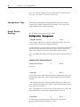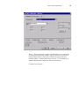
1
Owner’s Guide 0300191-04 Rev. A CONTROLLOGIX™ UNIVERSAL ANALOG INPUT MODULE Catalog Number: 1756sc-IF8u Important Notes 1. Please read all the information in this owner’s guide before installing the product. 2. The information in this owner's guide applies to hardware version A and firmware version 2.0 or later. 3. This guide assumes that the reader has a full working knowledge of the relevant processor. Notice The products and services described in this owner's guide are useful in a wide variety of applications. Therefore, the user and others responsible for applying the products and services described herein are responsible for determining their acceptability for each application. While efforts have been made to provide accurate information within this owner's guide, Spectrum Controls assumes no responsibility for the accuracy, completeness, or usefulness of the information herein. Under no circumstances will Spectrum Controls be responsible or liable for any damages or losses, including indirect or consequential damages or losses, arising out of either the use of any information within this owner's guide or the use of any product or service referenced herein. No patent liability is assumed by Spectrum Controls with respect to the use of any of the information, products, circuits, programming, or services referenced herein. The information in this owner's guide is subject to change without notice. LimitedWarranty Spectrum Controls warrants that its products are free from defects in material and workmanship under normal use and service, as described in Spectrum Controls literature covering this product, for a period of 1 year. The obligations of Spectrum Controls under this warranty are limited to replacing or repairing, at its option, at its factory or facility, any product which shall, in the applicable period after shipment, be returned to the Spectrum Controls facility, transportation charges prepaid, and which after examination is determined, to the satisfaction of Spectrum Controls, to be thus defective. This warranty shall not apply to any such equipment which shall have been repaired or altered except by Spectrum Controls or which shall have been subject to misuse, neglect, or accident. In no case shall the liability of Spectrum Controls exceed the purchase price. The aforementioned provisions do not extend the original warranty period of any product which has either been repaired or replaced by Spectrum Controls. Preface Read this preface to familiarize yourself with the rest of the owner’s guide. This preface covers: • who should use this guide • what this guide covers • related Allen-Bradley documents • terms & abbreviations you should know Who Should Use This Guide Use this guide if you design, install, program, or maintain a control system that uses Allen-Bradley ControlLogix Controllers. You should have a basic understanding of ControlLogix products. You should also understand electronic process control and the ladder program instructions required to generate the electronic signals that control your application. If you do not, contact your local Allen-Bradley representative for the proper training before using these products. What This Guide Covers Related AllenBradley Documents This guide covers the 1756sc-IF8u universal analog input module. It contains the information you need to install, wire, use, and maintain these modules. It also provides diagnostic and troubleshooting help should the need arise. Table A lists several Allen-Bradley documents that may help you as you use these products. Table A. Related Allen-Bradley documents Allen-Bradley Doc. No. Title Publication Number 1756-PA72, ControlLogix Power Supply Installation -PB72 Instructions 1756-5.1 1756-A4, ControlLogix Chassis Installation Instructions 1756-5.2 -A7, -A10, -A13, -A17 vi ControlLogix™ Universal Analog Input Modules 1756 Series ControlLogix Module Installation Instructions (Each module has separate document for installation) 1756-L1, Logix5550 Controller User Manual -L1M1, -L1M2 1756-DHRIO ControlLogix Data Highway Plus Communication Interface Module User Manual 1756-5.5, -5.42 1756-6.5.12 1756-6.5.2 1756-ENET ControlLogix Ethernet Communication Interface Module User Manual 1756-6.5.1 To obtain a copy of any of the Allen-Bradley documents listed, contact your local Allen-Bradley office or distributor. Terms & Abbreviations You Should Know You should understand the following terms and abbreviations before using this guide. A/D - Refers to analog-to-digital conversion. The conversion produces a digital value whose magnitude is proportional to the instantaneous magnitude of an analog input signal. Attenuation – The reduction in magnitude of a signal as it passes through a system. The opposite of gain. Channel – Refers to one of eight, small-signal analog input interfaces to the module’s terminal block. Each channel is configured for connection to a input device, and has its own configuration and status words. Chassis – See rack. CJC - (Cold Junction Compensation) The means by which the module compensates for the offset voltage error introduced by the temperature at the junction between the thermocouple lead wire and the input terminal block (the cold junction). Common mode rejection ratio (CMRR) - The ratio of a device’s differential voltage gain to common mode voltage gain. Expressed in dB, CMRR is a comparative measure of a device’s ability to reject interference caused by a voltage common to its terminal relative to ground. Common mode voltage – The voltage difference between the negative terminal and analog common during normal differential operation. Preface vii Cut-off frequency - The frequency at which the input signal is attenuated 3 dB by the digital filter. Frequency components of the input signal that are below the cut-off frequency are passed with under 3 dB of attenuation for low-pass filters. dB (decibel) – A logarithmic measure of the ratio of two signal levels. Digital filter - A low-pass mathmatic single order filter applied to the A/D signal. The digital filter provides high-frequency noise rejection. Effective resolution – The number of bits in the channel data word that do not vary due to noise. Local System - A control system with I/O chassis within several feet of the processor. LSB (least significant bit) – The bit that represents the smallest value within a string of bits. Mulitplexer – A switching system that allows several input signals to share a common A/D converter. Normal mode rejection (differential mode rejection) – A logarithmic measure, in dB, of a device’s ability to reject noise signals between or among circuit signal conductors, but not between the equipment grounding conductor or signal reference structure and the signal conductors. Module update time – See channel update time. Remote system - A control system where the chassis can be located several thousand feet from the processor chassis. Chassis communication is via the 1756-DHRIO and 1756-ENET Adapter. Resolution – The smallest detectable change in a measurement, typically expressed in engineering units (e.g. 0.15 °C) or as a number of bits. For example, a 12-bit system has 4096 possible output states. It can therefore measure 1 part in 4096. See also effective resolution. RTD (Resistance Temperature Detector) - A temperature sensing element with 2, 3, 4, lead wires. It uses the basic characteristics that electrical resistance of metals increases with temperature. When a small current is applied to the RTD, it creates a voltage that varies with temperature. This voltage is processed and converted by the RTD module into a temperature value. Sampling time - The time required by the A/D converter to sample an input channel. viii ControlLogix™ Universal Analog Input Modules Step response time – The time required for the A/D signal to reach 95% of its expected, final value, given a full-scale step change in the output data word. Tags - Identifiers for configuration, data, and status information found withing the module. Tags allow the user to modify specific module attributes and view data and status. Update time – The time for the module to sample and convert a channel input signal and make the resulting value available to the ControlLogix processor. Table of Contents Preface v Module Overview 1 Installing And Wiring Your Module 9 Operation Within the ControlLogix System 23 Programming Your Module 29 Who Should Use This Guide ................................................................................... v What This Guide Covers .......................................................................................... v Related Allen-Bradley Documents ........................................................................... v Table A. Related Allen-Bradley documents ............................................................. v Terms & Abbreviations You Should Know ............................................................. vi General Description .................................................................................................. 1 Detailed Specifications ............................................................................................. 2 Hardware Features .................................................................................................... 3 Diagnostic LEDs ....................................................................................................... 4 System Overview ...................................................................................................... 4 System Operation ..................................................................................................... 5 Module Operation .................................................................................................... 5 Compatibility with Thermocouple, Current, and Millivolt Devices & Cables ......... 6 Electrostatic Damage ................................................................................................ 9 Power Requirements ............................................................................................... 10 Table 2.1 Maximum current drawn by the module ................................................. 10 Module Installation and Removal .......................................................................... 10 Figure 2.1 Module insertion into a rack ................................................................ 13 Figure 2.2 Terminal block diagram with keying ..................................................... 14 Wiring Your Module .............................................................................................. 14 Preparing and Wiring the Cables ........................................................................... 15 Terminal Block Layout ............................................................................................ 16 Wiring Voltage/Current Inputs the IF8u Module ................................................... 17 Wiring RTD or Resistance Sensors to the IF8u Module ....................................... 18 Wiring Thermocouples to the IF8u Module .......................................................... 20 Ownership and Connections .................................................................................. 23 Using RSNetWorx and RSLogix 5000 ..................................................................... 23 Direct Connections ................................................................................................. 24 Module Operation .................................................................................................. 24 Modules in a Local Chassis ................................................................................... 25 Requested Packet Interval (RPI) ............................................................................ 25 Modules in a Remote Chassis ................................................................................ 26 Listen-Only Mode .................................................................................................. 27 Multiple Owners of Input Modules ....................................................................... 27 Configuration Changes in an Input Module with Multiple Owners ...................... 28 Module Installation ................................................................................................ 29 Adding Your Module to a Project .......................................................................... 29 Configuring module attributes: Configuration Tags .............................................. 34 x ControlLogix™ Universal Analog Input Modules Configuration, Data, and Status Tags 37 Programming Examples 55 Troubleshooting 61 Maintaining Your Module And Ensuring Safety 65 Module Specifications 69 Thermocouple Descriptions 75 Send Configuration Data to the Module ................................................................ 37 Configuration Tags ................................................................................................. 38 Global Module Settings .......................................................................................... 38 Channel Specific Settings ....................................................................................... 43 Input Tags .............................................................................................................. 50 Fault and Status Reporting Tags ........................................................................... 50 Module Data Tags .................................................................................................. 53 Initial Programming ................................................................................................. 55 Figure 5.1 Sample Ladder Logic ............................................................................ 56 Using Module Indicators to Troubleshoot ............................................................ 61 Using RSLogix 5000 to Troubleshoot Your Module .............................................. 62 Module Configuration Errors ................................................................................. 64 Preventive Maintenance ........................................................................................ 65 Safety Considerations ............................................................................................ 65 Electrical Specifications .......................................................................................... 69 Physical Specifications .......................................................................................... 70 Environmental Specifications ................................................................................. 70 Input Specifications ............................................................................................... 70 J Type Thermocouples ........................................................................................... 75 K Type Thermocouples .......................................................................................... 77 T Type Thermocouples .......................................................................................... 79 E Type Thermocouples .......................................................................................... 81 R Type Thermocouples .......................................................................................... 83 S Type Thermocouples .......................................................................................... 84 B Type Thermocouples .......................................................................................... 86 N Type Thermocouples .......................................................................................... 87 References .............................................................................................................. 90 Table of Contents Using Grounded Junction, Ungrounded Junction, and Exposed Junction Thermocouples 97 Programming Your Module 101 xi Thermocouple Types .............................................................................................. 97 Grounded Junction ................................................................................................. 98 Ungrounded (Insulated) Junction .......................................................................... 98 Exposed Junction ................................................................................................... 98 Isolation .................................................................................................................. 98 Module Installation .............................................................................................. 101 Adding Your Module to a Project ........................................................................ 101 Declaration of Conformity .................................................................................... 105 xii ControlLogix™ Universal Analog Input Modules Chapter 1 Module Overview This chapter describes the universal analog input module and explains how the ControlLogix controller reads analog input data from the module. Read this chapter to familiarize yourself further with your universal analog input module. This chapter covers: • general description and hardware features • an overview of system and module operation General Description This module is designed exclusively for use in the Allen-Bradley ControlLogix 1756 I/O rack systems. The module stores digitally converted thermocouple, RTD, resistance, millivolt (mV), volt (V), milliamp (mA), and CJC temperature analog data in its image table for retrieval by all ControlLogix processors. Following is a list of features available on the IF8u module that allow their use in a wide variety of applications. · Removal and insertion under power (RIUP) - a system feature that allows you to remove and insert modules while chassis power is applied · Producer/consumer communications - an intelligent data exchange between modules and other system devices in which each module produces data without having been polled · Rolling timestamp of data - 15 bit module-specific rolling timestamp with millisecond resolution which indicates when data was sampled/applied. This timestamp may be used to calculate the interval between channel or updates · System timestamp of data - 64 bit system clock places a timestamp on the transfer of data between the module and its owner controller within the local chassis · IEEE 32 bit floating point format · On-Board Features, such as custom User Scaling, Process Alarms, Rate Alarms, Digital Filtering, and Under/Overrange Detection · Automatic Calibration - analog I/O modules may perform autocalibration on a channel-by-channel or module-wide basis to reduce drift inaccuracies due to module ambient temperature changes. · Class I/Division 2, UL, CSA, CE, and FM Agency Certification 2 ControlLogix™ Counter Module Detailed Specifications Input Ranges The following tables provide compatibility information on the supported thermocouple types and their associated temperature ranges, the supported RTD types and their associated temperature ranges, as well as the millivolt, volt, milliamp and resistance input types supported by the IF8u module. To determine the practical temperature range of your thermocouple, refer to the specifications in appendices A and B. Table 1.1 Thermocouple Temperature Ranges Type °C Temperature Range °F Temperature Range J K T B E R S N C CJC Sensor -210°C to 1200°C -270°C to 1372°C -270°C to 400°C 300°C to 1820°C -270°C to 1000°C 0°C to 1768°C 0°C to 1768°C -210°C to 1300°C 0°C to 2315°C 0°C to 90°C -346°F to 2192°F -454°F to 2502°F -454°F to 752°F 572°F to 3308°F -454°F to 1832°F 32°F to 3214°F 32°F to 3214°F -346°F to 2372°F 32°F to 4199°F 32°F to 194°F Table 1.2 RTD Temperature Ranges Type °C Temp Range °F Temp Range Platinum (385) 100 Ohm -200°C to +850°C 200 Ohm -200°C to +850°C 500 Ohm -200°C to +850°C 1000 Ohm -200°C to +850°C -328°F to +1562°F -328°F to +1562°F -328°F to +1562°F -328°F to +1562°F Platinum (3916) 100 Ohm -200°C to +630°C 200 Ohm -200°C to +630°C 500 Ohm -200°C to +630°C 1000 Ohm -200°C to +630°C -328°F to +1166°F -328°F to +1166°F -328°F to +1166°F -328°F to +1166°F Copper (426) 10 Ohm -100°C to +260°C -148°F to +500°F Nickel (618) 120 Ohm -100°C to + 260°C 200 Ohm -100°C to + 260°C 500 Ohm -100°C to + 260°C 1000 Ohm -100°C to + 260°C -148°F to +500°F -148°F to +500°F -148°F to +500°F -148°F to +500°F Nickel (672) 120 Ohm -80°C to +260°C -112°F to + 500°F Nickel/Iron (518) 604 Ohm -100°C to +200°C -148°F to +392°F The digits in parenthisis following the RTD type represent the temperature coefficient of resistance (alpha, a), which is defined as the resistance change per Ohm per°°C. For instance, Platinum 385 refers to a platinum RTD with a = 0.00385 Ohms/Ohm - °C, or simply 0.00385/°°C. Chapter 1: Module Overview 3 Table 1.3 Millivolt Input Ranges Stated Actual -50 to +50 mV (-75 to +75 mV) -150 to +150 mV (-175 to +175 mV) 0 to +5.0 V (-0.5 to +5.5 V) 1.0 to +5.0 V (0.5 to +5.5 V) 0 to 10.0 V (-0.5 to 10.0 V) -10.0 to +10.0 V (-10.0 to +10.0 V) Table 1.4 Current Input Ranges 4 to 20 mA (-3.5 to +21.5mA) 0 to 20 mA (0 to +21.5mA) Table 1.5 Resistance Input Range 0 to 250 Ohms 0 to 500 Ohms 0 to 1000 Ohms 0 to 2000 Ohms 0 to 3000 Ohms 0 to 4000 Ohms All eight input channels are individually configurable for RTD, resistance, thermocouple, millivolt, volt, or milliamp input types. Each input channel provides wire-off input, over-range, and under-range detection and indication, when enabled. Hardware Features The module fits into any single slot for I/O modules in a ControlLogix modular system. The module has a unique generic profile which may be configured using your RSLogix 5000 programming software. The module utilizes one removable terminal block, that provides connections for the eight input channels. There are two cold-junction compensation (CJC) sensors that compensate for the cold junction at ambient temperature rather than at freezing (0°C). There are eight current sources for supplying the RTD or resistance sensors. The module is configured through RSLogix 5000 software, defining RTD, resistance, current or voltage input paths. 4 ControlLogix™ Counter Module Table 1.6 Hardware Features Hardware Function OK LED Displays communication and fault status of the module Cal LED Displays a fault condition Side Label (Nameplate) Provides module information Removable Terminal Block Provides electrical connection to input devices Door Label Permits easy terminal identification Self Locking Tabs Secure module in chassis slot Terminal Block Switch Locks the RTB to the module. Diagnostic LEDs The module contains diagnostic LEDs that help you identify the source of problems that may occur during power-up or during normal operation. Power-up and diagnostics are explained in Chapter 7, Testing Your Module. System Overview The module communicates with the ControlLogix processor and receives +5 Vdc and +24 Vdc power from the system power supply through the parallel backplane interface. You may install as many universal modules in the system as the power supply can support. Channels (0 through 7) can receive input signals from RTDs, resistance sources, thermocouples, millivolt, volt, or milliamp devices. When configured for thermocouple input types, the module converts analog input voltages into cold-junction compensated and linearized, digital temperature readings. The module uses the National Institute of Standards and Technology (NIST) linearization tables based on ITS-90 for thermocouple linearization. When configured for RTD input types, the module converts the analog input voltages into digital temperature readings, based on the alpha type, wire type, and ohms specified. The standards used are the JIS C 16041997 for the Pt 385 RTD types, the JIS C 1604-1989 for the Pt 3916 RTD types, SAMA RC21-4-1966 for the 10. Cu 426 RTD, DIN 43760 Sept. 1987 for the 120. Ni 618 RTD, and MINCO Application Aid #18 May 1990 for the 120. Ni 672 RTD.When configured for millivolt, volt, milliamp, or resistance analog inputs, the module converts the analog values directly into floating point values. For those input types, the module assumes that the input signal is linear prior to input into the module. Chapter 1: Module Overview 5 Table 1.6 Hardware Features Hardware Function OK LED Displays communication and fault status of the module Cal LED Displays a fault condition Side Label (Nameplate) Provides module information Removable Terminal Block Provides electrical connection to input devices Door Label Permits easy terminal identification Self Locking Tabs Secure module in chassis slot Terminal Block Switch Locks the RTB to the module. System Operation At power-up, the module checks internal circuits, memory, and basic functions. During this time the Cal LED remains on. If the module does not find any faults, it turns off the Cal LED. After completing power-up checks, the module wait for a connection to an owner controller then valid channel configuration data from your ladder logic program. After channel configuration data is transferred, and one or more channels are enabled, the module continuously converts the inputs to floating point data for use in your ladder program. Each time the module reads an input channel, the module tests that data for a fault, i.e. over-range, or under-range condition. If it detects an overrange or under-range condition, the module sets a unique bit in the status tags. Module Operation The module’s input circuitry consists of eight differential analog inputs, multiplexed into an A/D converter. The A/D converter reads the analog input signals and converts them to floating point values.. The input circuitry also continuously samples the CJC sensors, if not disabled and compensates for temperature changes for thermocouples at the cold junction (terminal block). The sensors must be Spectrum Controls supplied temperature sensors. The module will not accept other CJC sensor inputs, and thermocouple inputs will not function properly if incorrect CJC sensors are used. Two CJC sensors are shipped with each module. 6 ControlLogix™ Counter Module Compatibility with Thermocouple, Current, and Millivolt Devices & Cables The module is compatible with the following standard types of thermocouples: B, E, J, K, N, R, S, T and C and extension wire. Refer to appendices B and C for details. The module is also compatible with a variety of voltage and current devices with an output of ±50, ±150 mV, 05V, 1-5V, 0-10V, ±10V, 0-20mA, and 4-20mA. To minimize interference from radiated electrical noise, we recommend twisted-pair and highly shielded cables such as the following: Table 1.7 Recommendations to minimize interference from radiated electrical noise For This Type of Device We Recommend This Cable (or equivalent) Thermocouple Type J EIL Corp. J20-5-502 Thermocouple Type K EIL Corp. K20-5-510 Thermocouple Type T EIL Corp. T20-5-502 Other Thermocouple Types consult with EIL Corp or other manufacturers mV, V, mAdevices Belden 8761, shielded, twisted-pair Compatibility with RTD and Resistance devices and cables The module is compatible 100. Platinum 385, 200. Platinum 385, 500. Platinum 385, 1000. Platinum 385, 100. Platinum 3916, 200. Platinum 3916, 500. Platinum 3916, 1000. Platinum 3916, 10. Copper 426, 120. Nickel 618 and 120. Nickel 672 RTD types and resistance inputs, and 3 possible wire types (2 wire, 3 wire, or 4 wire). Each RTD input individually supports three input pins on the terminal block: one excitation current source (EXC+), one sense positive (IN+) and one sense negative (IN-). Only those pins are connected that are required by the selected RTD or resistance wire type. For 2, 3, or 4 wire configurations, the module can support a maximum combined cable length associated with an overall cable impedance of 25 ohms or less without exceeding its input limitations. The accuracy specifications provided herein do not include errors associated with unbalanced cable impedance. Since the operating principle of the RTD and resistance inputs is based on the measurement of resistance, take special care in selecting your input cable. For 2-wire or 3-wire configuration, select a cable that has a consistent impedance throughout its entire length. For 2-wire configurations, we recommend that you use Belden #9501 (or equivalent). For 3-wire configurations, we recommend that you use Belden #9533 (or equivalent) for short installation runs (less than 100 feet) or use Belden #83503 (or equivalent) for longer runs (greater than 100 feet) and in high humidity environments. Chapter 1: Module Overview Table 1.8 Cable Specifications Description For Belden #9501 Belden#9533 Belden#83503 2-wire RTDs and 3-wire RTDs and 3-wire RTDs and potentiometers. potentiometers. Short potentiometers. When used? Long runs less than 100 feet runs greater than 100 7 8 ControlLogix™ Counter Module Chapter 2 Installing And Wiring Your Module Read this chapter to install and wire your module. This chapter covers: • avoiding electrostatic damage • determining power requirements • installing the module • wiring signal cables to the module’s terminal block Electrostatic Damage Electrostatic discharge can damage semiconductor devices inside this module if you touch backplane connector pins. Guard against electrostatic damage by observing the following precautions: CAUTION ! ELECTROSTATICALLY SENSITIVE COMPONENTS • Before handling the module, touch a grounded object to rid yourself of electrostatic charge. • When handling the module, wear an approved wrist strap grounding device. • Handle the module from the front, away from the backplane connector. Do not touch backplane connector pins. • Keep the module in its static-shield container when not in use or during shipment. Failure to observe these precautions can degrade the module’s performance or cause permanent damage. 10 ControlLogix™ Universal Analog Input Module Power Requirements The module receives its power through the ControlLogix chassis backplane from the fixed or modular +5 VDC and +24 VDC chassis power supply. The maximum current drawn by the module is shown in the table below. Table 2.1. Maximum current drawn by the module 5VDC Amps 0.230 24VDC Amps 0.075 Using your module in the ControlLogix System Place your module in any slot of a ControlLogix modular, or modular expansion chassis. An analog I/O module translates an analog signal into, or from, a corresponding digital representation which controllers can easily operate on for control purposes. A ControlLogix I/O module mounts in a ControlLogix chassis and uses a Removable Terminal Block (RTB) to connect all field-side wiring. Before you install and use your module you should have already: · installed and grounded a 1756 chassis and power supply. · ordered and received an RTB for your application. Important: RTBs are not included with your module purchase. Specify Allen Bradley Part Number: 1756-TBCH - 36 position screw terminals 1756-TBS6H - 36 position press terminals Module Installation and Removal When installing the module in a chassis, it is not necessary to remove the terminal blocks from the module. However, if the terminal blocks are removed, use the write-on label located on the side of the terminal blocks to identify the module location and type. Chapter 2: Installing And Wiring Your Module 11 Preventing Electrostatic Discharge This module is sensitive to electrostatic discharge. ! ATTENTION: Electrostatic discharge can damage integrated circuits or semiconductors if you touch backplane connector pins. Follow these guidelines when you handle the module: · · · · · · Touch a grounded object to discharge static potential Wear an approved wrist-strap grounding device Do not touch the backplane connector or connector pins Do not touch circuit components inside the module If available, use a static-safe work station When not in use, keep the module in its static-shield box Removal and Insertion Under Power These modules are designed to be installed or removed while chassis power is applied. ! ATTENTION: When you insert or remove a module while backplane power is applied, an electrical arc may occur. An electrical arc can cause personal injury or property damage by: · sending an erroneous signal to your system’s field devices causing unintended machine motion or loss of process control. · causing an explosion in a hazardous environment. Repeated electrical arcing causes excessive wear to contacts on both the module and its mating connectors. Worn contacts may create electrical resistance that can affect module operation. Compliance to European Union Directives If this product bears the CE marking, it is approved for installation within the European Union and EEA regions. It has been designed and tested to meet the following directives. EMC Directive This product is tested to meet Council Directive 89/336/EEC Electromagnetic Compatibility (EMC) and the following standards, in whole or in part, documented in a technical construction file: 12 ControlLogix™ Universal Analog Input Module EN 61010-1 and EN 61131-2, EN61000-6-2:2001, EN61000-6-4:2001 EN61010-1:2001 This product is intended for use in an industrial environment. Low Voltage Directive This product is tested to meet Council Directive 73/23/EEC Low Voltage, by applying the safety requirements of EN 61131-2 Programmable Controllers, Part 2 - Equipment Requirements and Tests. For specific information required by , EN61131-2:1994 + A11:1996 + A12:2000, see the appropriate sections in this publication, as well as the following Allen-Bradley publications: · Industrial Automation Wiring and Grounding Guidelines For Noise Immunity, publication 1770-4.1 · Automation Systems Catalog, publication B111 This equipment is classified as open equipment and must be installed (mounted) in an enclosure during operation as a means of providing safety protection. ! CAUTION POSSIBLE EQUIPMENT OPERATION ATTENTION: The module is designed to support Removal and Insertion Under Power (RIUP). However, when you remove or insert an RTB with field-side power applied, unintended ol can occur . control mac hine motion or loss of pr ocess contr Exercise extreme caution when using this feature. ! WARNING The 1756sc-IF8U module is to be used only with the AllenBradley 1756 ControlLogix System. Chapter 2: Installing And Wiring Your Module 13 To insert your module into the rack, follow these steps: 1. Align the circuit board of your module with the card guides at the top and bottom of the chassis. Figure 2.1. Module insertion into a rack 2. Key the RTB in positions that correspond to unkeyed module positions. Insert the wedge-shaped tab on the RTB with the rounded edge first. Push the tab onto the RTB until it stops. Keying the Removable Terminal Block Key the RTB to prevent inadvertently connecting the incorrect RTB to your module. When the RTB mounts onto the module, keying positions will match up. For example, if you place a U-shaped keying band in position #4 on the module, you cannot place a wedge-shaped tab in #4 on the RTB or your RTB will not mount on the module. We recommend that you use a unique keying pattern for each slot in the chassis. 1. Insert the U-shaped band with the longer side near the terminals. Push the band onto the module until it snaps into place. 14 ControlLogix™ Universal Analog Input Module Figure 2.2. Wiring Your Module Terminal block diagram with keying Follow these guidelines to wire your input signal cables: • Power, input, and output (I/O) wiring must be in accordance with Class I, Division 2 wiring methods [Article 501-4(b) of the National Electrical Code, NFPA 70] and in accordance with the authority having jurisdiction. • Peripheral equipment must be suitable for the location in which it is used. • Route the field wiring away from any other wiring and as far as possible from sources of electrical noise, such as motors, transformers, contactors, and ac devices. As a general rule, allow at least 6 in. (about 15.2 cm) of separation for every 120 V of power. • Routing the field wiring in a grounded conduit can reduce electrical noise further. • If the field wiring must cross ac or power cables, ensure that they cross at right angles. • To limit the pickup of electrical noise, keep thermocouple, RTD, millivolt, and milliamp signal wires as far from power and load lines as possible. • For improved immunity to electrical noise, use Belden 8761 (shielded, twisted pair) or equivalent wire for millivolt sensors; or use shielded, twisted pair thermocouple extension lead wire specified by the thermocouple or RTD manufacturer. Using the incorrect type of thermocouple extension wire or not following the correct polarity may cause invalid readings. • Ground the shield drain wire at only one end of the cable. The preferred location is at the shield connections at the ControlLogix chassis. (Refer to IEEE Std. 518, Section 6.4.2.7 or contact your sensor manufacturer for additional details.) 15 Chapter 2: Installing And Wiring Your Module • Keep all unshielded wires as short as possible. • To limit overall cable impedance, keep input cables as short as possible. Locate your I/O chassis as near the RTD or thermocouple sensors as your application will permit. • Tighten screw terminals with care. Excessive tightening can strip a screw. The RTB terminations can accommodate 2.1…0.25 mm2 (14…22 AWG) shielded wire and a torque of 0.5 N•m (4.4 lb•in.). • Follow system grounding and wiring guidelines found in your ControlLogix Installation and Operation Manual. Preparing and Wiring the Cables To prepare and connect cable leads and drain wires, follow these steps: Signal Wires Cable (Remove foil shield and drain wire from sensor-end of the cable.) Drain Wire Signal Wires (At the module-end of the cable, extract the drain wire but remove the foil shield.) 1. At each end of the cable, strip some casing to expose individual wires. 2. Trim signal wires to 5-inch lengths beyond the cable casing. Strip about 3/16 inch (4.76 mm) of insulation to expose the ends of the wires. 3. At the module-end of the cables (see figure above): - extract the drain wire and signal wires - remove the foil shield - bundle the input cables with a cable strap 4. Connect pairs of drain wires together, Channels 0 and 1, Channels 2 and 3, Channels 4 and 5, Channels 6 and 7. Keep drain wires as short as possible. 5. Connect the drain wires to the grounding lug on the PLC chassis. 6. Connect the signal wires of each channel to the terminal block. Important: Only after verifying that your connections are correct for each channel, trim the lengths to keep them short. Avoid cutting leads too short. 7. At the source-end of cables from mV devices: - remove the drain wire and foil shield - apply shrink wrap as an option 16 ControlLogix™ Universal Analog Input Module - connect to mV devices keeping the leads short Important: If noise persists, try grounding the opposite end of the cable, instead (Ground one end only.) Terminal Block Layout The following figure shows the general terminal block layout. The input signal type will determine which pins are used. Chapter 2: Installing And Wiring Your Module Wiring Voltage/ Current Inputs the IF8u Module 17 Voltage inputs use the terminal block pins labelled IN+ and INCurrent inputs use the terminal block pins labelled IN+ and INVoltage Inputs EXC+ IN+ Voltage + Voltage - INiRTN CABLE SHIELD Current Inputs ADD JUMPER EXC+ IN+ Current + INiRTN Current CABLE SHIELD 18 ControlLogix™ Universal Analog Input Module Wiring RTD or Resistance Sensors to the IF8u Module The IF8u module supports two, three, and four wire RTDs or resistance inputs connected individually to the module as shown in the figure below. These are: * 2-wire RTDs, which are composed of 2 RTD lead wires (EXC+ and IN- with a jumper between EXC+ and IN+) * 3-wire RTDs, which are composed of a 2 Signal and 1 RTD return lead wires (EXC+ and IN+ with a the return RTD lead to IN-) * 4-wire RTDs, which are composed of 2 Signal and 2 RTD return lead wires (EXC+ and IN+ with a the return RTD lead to IN-) The fourth lead is not used so wiring is identical to 3 wires RTDs. * 2- wire Resistance, which is composed of 2 leads (EXC+ and IN- with a jumper between EXC+ and IN+) * 3- wire Resistance, which is composed of 3 leads (EXC+ IN+ and IN-) and the resistance lies between IN+ and INIn any RTD sensing system, it is important that the lead and sense wire resistances are matched as much as possible. The lead lengths, and their resulting impedances, must be matched and kept small to eliminate the introduction of connectivity errors. The 3/4-wire RTDs are the most accurate, with 2-wire RTDs being the most inaccurate. In 2-wire the lead resistance adds error to the resulting degree reading. With a 1.008mA current source, 1Ω of lead resistance adds 1.008µV, or 2.82°C error, with the 100Ω 385 alpha type. To gain an understanding of how lead resistance affects RTD readings, the µV/C for each RTD type is listed below. Chapter 2: Installing And Wiring Your Module RTD Type Current Source V/°C 100Ω Pt 385 200Ω Pt 385 500Ω Pt 385 1000Ω Pt 385 1.008mA 1.008mA 252µA 252µA 357µV/°C 714µV/°C 447µV/°C 893µV/°C 100Ω Pt 3916 200Ω Pt 3916 500Ω Pt 3916 1000Ω Pt 3916 1.008mA 1.008mA 252µA 252µA 377µV/°C 754µV/°C 472µV/°C 941µV/°C 120Ω Ni 618 200Ω Ni 618 500Ω Ni 618 1000Ω Ni 618 1.008mA 1.008mA 252µA 252µA 694µV/°C 1389µV/°C 867µV/°C 1733µV/°C 10Ω Cu 426 252µA 9.7µV/°C 120Ω Ni 672 1.008mA 929µV/°C 19 The accuracies specified for the IF8u RTDs do not include errors due to lead resistance imbalances. Important: To ensure temperature or resistance value accuracy, the resistance difference of the cable lead wires must be equal to or less than 0.01 ohms. Important: Keep total lead resistance as small as possible and less than 25 ohms. There are several ways to insure that the lead values match as closely as possible. They are as follows: * Use quality cable that has a small tolerance impedance rating. * Use a heavy gauge lead wire which has less resistance per foot. Wiring Thermocouples to the IF8u Module One end of thermocouple to IN+ Other end of thermocouple to INThermocouple Inputs EXC+ IN+ TC + TC - INiRTN CABLE SHIELD CJC Sensors CJC+ CJC- White (With Potted Sensor) White (No Sensor) For cold junction compensation be sure the two supplied thermistors are connected. One should be connected between CJC0-IN+ and CJC0-INand the other should be connected between CJC1-IN+ and CJC1-IN-. Also be sure configuration tag “.CJDisable” is set to zero to perform cold junction compensation for thermocouple inputs Cold Junction Compensation (CJC) ! CAUTION POSSIBLE EQUIPMENT OPERATION Both CJCs are critical to ensure accurate thermocouple input readings at each channel. Failure to observe this precaution can cause unintended equipment operation and damage. 22 ControlLogix™ Universal Analog Input Module Chapter 3: Operation within the System 23 Operation Within the ControlLogix System This chapter describes how the 1756sc-IF8u analog module works within the ControlLogix system. This chapter covers: • Ownership and connections to the module • Direct connections • Listen only mode • Configuration changes with multiple owners. Ownership and Connections Every I/O module in the ControlLogix system must be owned by a Logix5550 Controller to be useful. This owner-controller stores configuration data for every module that it owns and can be local or remote in regard to the I/O module’s position. The owner sends the I/O module configuration data to define the module’s behavior and begin operation within the control system. Each ControlLogix I/O module must continuously maintain communication with its owner to operate normally. Typically, each module in the system will have only 1 owner. Input modules can have more than 1 owner. Output modules, however, are limited to a single owner. Using RSNetWorx and RSLogix 5000 The I/O configuration portion of RSLogix5000 generates the configuration data for each I/O module in the control system, whether the module is located in a local or remote chassis. A remote chassis, also known as networked, contains the I/O module but not the module’s owner controller. Configuration data is transferred to the controller during the program download and subsequently transferred to the appropriate I/ O modules. I/O modules in the same chassis as the controller are ready to run as soon as the configuration data has been downloaded. You must run RSNetWorx to enable I/O modules in the networked chassis. Running RSNetWorx transfers configuration data to networked modules and establishes a Network Update Time (NUT) for ControlNet that is compliant with the desired communications options specified for each module during configuration. If you are not using I/O modules in a networked chassis, running RSNetWorx is not necessary. However, anytime a controller references an I/O module in a networked chassis, RSNetWorx must be run to configure ControlNet. Follow these general guidelines when configuring I/O modules: 1. Configure all I/O modules for a given controller using RSLogix 5000 and download that information to the controller. 24 ControlLogix™ Universal Analog Input Module 2. If the I/O configuration data references a module in a remote chassis, run RSNetWorx. Important: RSNetWorx must be run whenever a new module is added to a networked chassis. When a module is permanently removed from a remote chassis, we recommend that RSNetWorx be run to optimize the allocation of network bandwidth. Direct Connections A direct connection is a real-time data transfer link between the controller and the device that occupies the slot that the configuration data references. When module configuration data is downloaded to an ownercontroller, the controller attempts to establish a direct connection to each of the modules referenced by the data. If a controller has configuration data referencing a slot in the control system, the controller periodically checks for the presence of a device there. When a device’s presence is detected, the controller automatically sends the configuration data. If the data is appropriate to the module found in the slot, a connection is made and operation begins. If the configuration data is not appropriate, the data is rejected and an error message displays in the software. In this case, the configuration data can be inappropriate for any of a number of reasons. The controller maintains and monitors its connection with a module. Any break in the connection, such as removal of the module from the chassis while under power, causes the controller to set fault status bits in the data area associated with the module. The RSLogix 5000 software may monitor this data area to announce the modules’ failures. Module Operation Modules in a Local Chassis In traditional I/O systems, controllers poll input modules to obtain their input status. Analog input modules in the ControlLogix system are not polled by a controller once a connection is established. The modules multicast their data periodically. Multicast frequency depends on the options chosen during configuration and where in the control system that input module physically resides. An input module’s communication, or multicasting, behavior varies depending upon whether it operates in the local chassis or in a remote chassis. The following sections detail the differences in data transfers between these set-ups. When a module resides in the same chassis as the owner controller, the following two configuration parameters will affect how and when the input module multicasts data: · Real Time Sample (RTS) configured via Real Time Sample tag. · Requested Packet Interval (RPI) configured via I/O module properties. Real Time Sample (RTS) Chapter 3: Operation within the System 25 This configurable parameter instructs the module to perform the following operations: 1. scan all of its input channels and store the data into on-board memory 2. multicast the updated channel data (as well as other status data) to the backplane of the local chassis Requested Packet Interval (RPI) This configurable parameter also instructs the module to multicast its channel and status data to the local chassis backplane. The RPI instructs the module to multicast the current contents of its on-board memory when the RPI expires, (i.e. the module does not update its channels prior to the multicast). Important: The RPI value is set during the initial module configuration using RSLogix 5000. It is important to note that the module will reset the RPI timer each time an RTS is performed. This operation dictates how and when the owner controller in the local chassis will receive updated channel data, depending on the values given to these parameters. If the RTS value is less than or equal to the RPI, each multicast of data from the module will have updated channel information. In effect, the module is only multicasting at the RTS rate. If the RTS value is greater than the RPI, the module will multicast at both the RTS rate and the RPI rate. Their respective values will dictate how often the owner controller will receive data and how many multicasts from the module contain updated channel data. Note: Even though data may be transfered at the RPI rate, the data will be indentical to the previous RTS data transfer. Modules in a Remote Chassis If an input module resides in a networked chassis, the role of the RPI and the module’s RTS behavior change slightly with respect to getting data to the owner. The RPI and RTS intervals still define when the module will multicast data within its own chassis (as described in the previous section), but only the value of the RPI determines how often the owner controller will receive it over the network. When an RPI value is specified for an input module in a remote chassis, in addition to instructing the module to multicast data within its own chassis, the RPI also “reserves” a spot in the stream of data flowing across the ControlNet network. The timing of this “reserved” spot may or may not coincide with the exact value of the RPI, but the control system will guarantee that the owner controller will receive data at least as often as the specified RPI. 26 ControlLogix™ Universal Analog Input Module The “reserved” spot on the network and the module’s RTS are asynchronous to each other. This means there are Best and Worst Case scenarios as to when the owner controller will receive updated channel data from the module in a networked chassis. Best Case RTS Scenario In the Best Case scenario, the module performs an RTS multicast with updated channel data just before the “reserved” network slot is made available. In this case, the remotely located owner receives the data almost immediately. Worst Case RTS Scenario In the Worst Case scenario, the module performs an RTS multicast just after the “reserved” network slot has passed. In this case, the ownercontroller will not receive data until the next scheduled network slot. Because it is the RPI and NOT the RTS which dictates when the module’s data will be sent over the network, we recommend the RPI value be set LESS THAN OR EQUAL TO the RTS to make sure that updated channel data is received by the owner controller with each receipt of data. Listen-Only Mode Any controller in the system can listen to the data from any I/O module (e.g. input data or “echoed” output data) even if the controller does not own the module (i.e. it does not have to hold the module’s configuration data to listen to the module). The “listen only” mode is set during the I/O configuration process. Choosing a ‘Listen-Only’ mode option allows the controller and module to establish communications without the controller sending any configuration data. In this instance, another controller owns the module being listened to. Important:Controllers using the Listen-Only mode continue to receive data multicast from the I/O module as long as a connection between an owner and I/O module is maintained. If the connection between all owners and the module is broken, the module stops multicasting data and connections to all ‘Listening controllers’ are also broken. Multiple Owners of Input Modules Because ‘Listening controllers’ lose their connections to modules when communications with the owner stop, the ControlLogix system will allow you to define more than one owner for input modules. Important: Only input modules can have multiple owners. If multiple owners are connected to the same input module, they must maintain identical configuration for that module. In the example below, Controller A and Controller B have both been configured to be the owner of the input module. Chapter 3: Operation within the System 27 When the controllers begin downloading configuration data, both try to establish a connection with the input module. Whichever controller’s data arrives first establishes a connection. When the second controller’s data arrives, the module compares it to its current configuration data (the data received and accepted from the first controller). If the configuration data sent by the second controller matches the configuration data sent by the first controller the connection is also accepted. If any parameter of the second configuration data is different from the first, the module rejects the connection and the user is informed by an error in the software. The advantage of multiple owners over a ‘Listen-only’ connection is that now either of the controllers can lose the connection to the module and the module will continue to operate and multicast data to the system because of the connection maintained by the other owner controller. Note: The previous discussion of multiple owners assues the configuration tag “.configrevnumber” is set to 1. Operation differs is the tag is set to 0. Refer to Chapter 5 for descriptions of this tag’s settings. Configuration Changes in an Input Module with Multiple Owners You must be careful when changing an input module’s configuration data in a multiple owner scenario. When the configuration data is changed in one of the owners, for example, Controller A, and sent to the module, that configuration data is accepted as the new configuration for the module. Controller B will continue to listen, unaware that any changes have been made in the module’s behavior. Important: When changing configuration for a module with multiple owners, we recommend the connection be inhibited. To prevent other owners from receiving potentially erroneous data, as described above, the following steps must be followed when changing a module’s configuration in a multiple owner scenario when online: 1. For each owner controller, inhibit the controller’s connection to the module in the software on the I/O Module Connection tab. 2. Make the appropriate configuration data changes in the software. 3. Repeat steps 1 and 2 for all owner controllers, making the exact same changes in all controllers. 4. Uncheck the Inhibit box in each owner’s configuration to reconnect each module. 28 ControlLogix™ Universal Analog Input Module Chapter 4 Programming Your Module This chapter explains how to program your module in the ControlLogix system. It also describes how the module’s input configuration are incorporated into your ladder logic program. Topics discussed include: • importing the module’s configuration profile • reviewing accessing and altering configuration options. • configuring the modules input type and filter settings • configuring alarms and limits Module Installation To incorporate the module into the system, you must use the RSLogix 5000 programming software. If you’re using RSLogix 5000 version 15 or greater, an AOP (Add-On-Profile) is available and can be downloaded from our website at (http://www.spectrumcontrols.com/downloads.htm). The AOP allows you to add the IF8U to the RSLogix 5000 pick list and contains custom configuration screens for the module. If you do plan to use the AOP, you can skip the remainder of this chapter. For those that plan to use RSLogix 5000 version 14 or older, the generic module profile must be used to add the IF8U to a new or existing project. An RSLogix 5000 sample project utilizing the generic module profile is available for download on our website at (www.spectrumcontrols.com/ downloads.htm). The ladder sample contains user defined input and configuration tags used to configure and read analog data from the IF8U module. The configuration tags control features such as the modules input type, channel input range, data format, filter frequency, etc. Adding Your Module to a Project The module has a unique set of tag definitions which are used to configure specific features. Chapter 5, Channel Configuration, Data, and Status, gives you detailed information about the data content of the configuration. These values are set using your programming software and ladder logic. Before you can use these feature you must first include the module into the project. 30 ControlLogix™ Universal Analog Input Module 1. Open the sample project with the IF8u information. Open your project. Drag and drop the IF8u module into the I/O configuration section of your project. 1. Open the sample project. 2. Open your new project. 3. Click once on the IF8u in the sample project. 4. Drag and drop it into the I/O Configuration section of your project. See Appendix D for the I/O module property details. Chapter 4: Programming Your Module 31 2. Drag and drop the IF8u user-defined data types from the sample project into your project. There are four IF8u user defined data types that need to be moved. ChannelConfig ChannelStatus IF8u_Config_Template IF8u_Input_Template 1. Click on the data type 2. Drag it into your new project. 3. Continue to drag and drop the data types until all four have been moved. Note: These can only be moved one at a time. 32 ControlLogix™ Universal Analog Input Module 3. Drag and drop the controller configuration tags from the sample project into your project. 1. Right click on the Controller Tags item of the sample project and select edit. 2. Right click on the Controller Tags item of your project and select edit. 3. Scroll down to the Controller tags of the sample project and select all the tags by highlighting them. 4. Drag and drop these tags into your project. Note: IF8u_Config and IF8u_Input contain the configuration, data and status tags for the IF8u module. The other tags are used for performing various functions to your module via ladder logic. Note: Be sure all tags are displayed before moving them. Select Display All from the Edit drop down window. Note: The “Local:3:I” and “Local:3:C” tags are not copied. Chapter 4: Programming Your Module 33 4. Create a new ladder logic routine in your project. 1. In your project, right mouse click on the MainRoutine item and select “New Routine...” IF8u was entered in the example above. 2. Double click on the MainRoutine item in the sample project and then double click on the added new routine in your project to display their corresponding ladder logic. 3. Left mouse inside the MainProgram ladder logic in the sample project and press crtl-A to select all the rungs. 4. Drag and drop these rungs over and add them to the new routine’s ladder logic. Note: You will need to delete the one blank “solid bar” rung either at the top or bottom of the routine which was left over from the newly created routine. 5. Now add a JSR ladder instruction in your MainRountine which calls this routine. Note: RSLogix 5000 will verify the ladder logic sample. You may receive errors regarding invalid tags. You will need to change the slot addressing in the logic to coordinate with the location of the IF8u. This completes the installation of module in the system 34 ControlLogix™ Universal Analog Input Module Configuring module attributes: Configuration Tags The module has settings that are global and channel specific. These are accessed via the controller tags. Specific information regarding these tag settings may be found in Chapter 5. Global module tags These settings are used globally by the module. They control features such as the module autocalibration modes, and various other attributes. Chapter 4: Programming Your Module 35 Channel Specific Tags These settings control channel specific behavior such as input type, range, filter frequency, units, and alarms. Specific information regarding these tags may be found in Chapter 5. Data Tags These tags represent the process data values in their final form. 36 ControlLogix™ Universal Analog Input Module Status Tags These tags report module status such as alarm conditions, faults, and errors. Chapter 37 5 Chapter 5: Channel Configuration, Data, and Status Choosing a Wiring Method The 1756-IF16 and 1756-IF8 modules support the following three wiring Configuration, Data, and Status Tags Read this chapter to: • send configuration data to the module • configure global module properties • configure each input channel • check each input channel’s data • check module and individual channel status This chapter outlines the detailed settings for the 1756sc-IF8u. These settings determine the modules input types, filter frequencies, scan rates, and various attributes. Detailed descriptions of these settings are available in the Tag Definition section of this chapter. Note: An AOP (Add-On_Profile) is availabe for the 1756sc-IF8U and can be downloaded from our website at (http://www.spectrumcontrols.com/ downloads.htm). Note: The following format is used to describe tags Tag Name Send Configuration Data to the Module Range Data Type After changing the configuration tags in this chapter you must then send them to the module. To do this you may perform any of these operations: 1. Inhibit then un-inhibit the module via the module properties dialog, Connection Tab 2. Reset the module via the modules properties dialog. Module Info tab. 3. Reset the module via ladder logic. See the “DoReset” rung in the sample ladder project. 4. Perform a “Set Attribute All” or Module Reconfigure message instruction via ladder logic. Refer to your sample program for information about the “DoSetAttrAll” command. 38 ControlLogix™ Universal Analog Input Module Note: If an invalid configuration is sent to the module a connection error will occur. See chapter 7 for a list of error codes. Configuration Tags Global Module Settings The following Global Module Settings and Channel Specific Settings sections allow custom configuration of the module. These tags can be found within the IF8u_config controller tag. The following tag settings are module related: Configuration Management .ConfigRevNumber 0, 1 BOOL 0: The module will always accept this configuration if valid. This value must be used for on-the-fly configuration changes. 1: In multiple owner systems if there is already a connection to the module then this configuration must match the one of the current connection in order for this controller to connect to the module.Channel On/Off Note: The Module Reconfigure message instruction sets this parameter to zero. Temperature Measurement: .RemoteTermination 0, 1 BOOL 0, 1 BOOL Not Used. .CJDisable 0: The cold junction compensation terminal block thermistors will be read. Thermocouple input values will be compensated based on the thermistor readings. 1: The cold junction compensation thermal block thermistors will not be read. Thermocouple input values will be compensated with the default 25 degC value plus CJCOffset. Note: 2 thermistors have been provided with the module to be installed on your terminal block if cold junction compensation is to be used. .TempMode 0, 1 BOOL 0: Temperatures for thermocouples, RTDs and the cold junction thermistors will be displayed in degrees Celsius. Chapter 5: Channel Configuration, Data, and Status 39 1: Temperatures for thermocouples, RTDs and the cold junction thermistors will be displayed in degrees Fahrenheit. -25 to +65 degC -45 to + 117 degF .CJOffset REAL A temperature offset added to the cold junction compensation temperature values. This is interpreted as degrees C if the .TempMode = 0 and degrees F if the .TempMode = 1. Module Sampling Time The universal module update time is defined as the time required for the module to sample and convert the input signals of all enabled input channels and make the resulting data values available to the processor. The sample time is influenced by the input type, filter frequency, CJC acquisition (if enabled) and autocal configuration settings. For example, when thermocouples are selected, it is necessary to perform a cold junction compensation, (CJC), measurement to obtain best possible accuracy. This CJC measurement occurs in a systematic fashion and adds approximately 26ms to the update time. The following tables illustrate the components used to calculate typical channel update times. Overhead: 5 ms - This must be included in all calculations and represents backplane communication and other service routines within the module. Filter Frequency: The channel filter frequency will impact timing. The following table shows associated time adders based on frequency selection. Filter Additional Time 10Hz 50/60Hz 100Hz 250Hz 1kHz 125 ms per channel 26 ms per channel 18 ms per channel 10 ms per channel 6 ms per channel 40 ControlLogix™ Universal Analog Input Module Input Type: Each input type has a specific settling time. Select each channel input type and add the time value. Time (ms) 0 3 3 3 3 3 3 3 3 4 4 4 4 4 4 4 4 8 8 8 8 8 Type All voltage, current, and thermocouple types 100_Pt_385 100_Pt_392 120_Ni_618 120_Ni_672 10_Cu_426 604_NiFe_518 0_250_Ohm 0_500_Ohm 200_Pt_385 500_Pt_385 200_Pt_392 500_Pt_392 200_Ni_618 500_Ni_618 0_1000_Ohm 0_2000_Ohm 1000_Pt_385 1000_Pt_392 1000_Ni_618 0_3000_Ohm 0_4000_Ohm Tag: .RangeType 8 12 16 20 21 22 23 24 9 10 13 14 17 18 25 26 11 15 19 27 28 Example 1: 4 channels with 200 Ohm PT 385 RTD (Input Type 9) at 100Hz filter = 18ms + 4ms = 22ms * 4 channels = 88ms 2 channels of voltage at 1khz = 2 * 6ms = 12ms 2 thermocouples at 250Hz = 2 * 10ms = 20ms Total = 5ms (overhead) + 26ms (CJC) + 88ms + 12ms + 20ms = 151ms (Actual measured = 158ms) Example 2: 8 channels, 0-4000 ohm (type 28) at 250Hz = 10ms + 8ms = 18ms * 8 = 144ms + 5ms = 149ms. (Actual measured = 117ms) Note: This is approximation only. The time changes because the software does not need to spend time setting up the ADC for another filter frequency if it is the same as the previous channel. The same applys for the the gain settings, etc. Example 2 illustrates there is a significant savings because the filter frequency and input type are the same. Note: If the autocalibration is enabled the module sampling time will increase by as much as 500ms when autocalibration is being performed. Chapter 5: Channel Configuration, Data, and Status .RealTimeSample 10-30,000 ms 41 INT The time in milliseconds that updated input data is to be sent from the module to the controller. If this value is smaller than the minimum update time to scan all input channels, then the actual rate will be greater than this value. In this case you may determine what the actual sample time is by subtracting two successive values of the .RollingTimeStamp input tag. Real Time Sampling (RTS) and Requested Packet Interval (RPI) This RealTimeSample tag instructs the module to scan its input channels and obtain all available data. After the channels are scanned, the module multicasts that data. This feature is used on a module-wide basis. During module configuration, you specify a Real Time Sampling (RTS) period via the .RealTimeSample tag and a Requested Packet Interval (RPI) period. Both of these features instruct the module to multicast data, but only the RTS feature instructs the module to scan its channels before multicasting. You may access the RPI in the Module Properties menu. 42 ControlLogix™ Universal Analog Input Module Automatic Calibration: Autocalibration is an automated input path calibration. This insures best possible accuracy under varying application conditions. Autocalibration may be turned on or off. When autocalibration is active you may also set the interval at which the calibration occurs. .DisableCyclicAutocal 0, 1 BOOL 0: Module auto-calibration is performed on power up, reset, and reconfiguration as well as according to the .CyclicAutocalPeriod. 1: Module auto-calibration is only performed on module power-up, reset, and reconfiguration. Note: Changing the following tags via the set attribute all or module reconfiguration message will not cause the auto-calibration to be performed upon acceptance of the configuration. .Alarm Enable .TenOhmOffset .LowSignal .HighEngineering .LLAlarmLimit .ProcessAlarmLatch .DigitalFilter .HighSignal .LAlarmLimit .HHAlarmLimit .CyclicAutocalPeriod 0-3 .RateAlarmLatch .RateAlarmLimit .LowEngineering .HighAlarmLimit .AlarmDeadband INT Perform module auto-calibration: 0: Only on powerup and reset. 1: Every 1 minute. 2: Every 10 minutes. 3: Every 30 minutes. Note: Options 1 through 3 are not valid if cyclic autocal is disabled. Chapter 5: Channel Configuration, Data, and Status Channel Specific Settings 43 The following settings allow you to configure individual channel parameters. Each channel, 0 through 7, has these tags. Channel On/Off: .DisableChannel 0, 1 BOOL 0: Channel is enabled. 1: Channel is disabled. You may decrease the module sampling time by disabling unused channels. Input Range/Type .RangeType 0-37 INT You can select from a series of operational ranges for each channel on your module. The range designates the minimum and maximum signals that are detectable by the module. In the case of thermocouple or RTD sensors the selected type dictates the linearization curve of the particular sensor. 0 = -0.05 to 0.05V (-0.075 to 0.075V) 1 = -0.15 to 0.15V (-0.175 to 0.175V) 2 = 0 to 5V (-0.5 to 5.5V) 3 = 1 to 5V (0.5 to 5.5V) 4 = 0 to 10V (-0.5 to 10.0V) 5 = -10.0 to 10.0V 6 = 0 to 20mA (0 to 21.5mA) 7 = 4 to 20mA (3.5 to 21.5mA) 8 = RTD 100Ω Pt 385 9 = RTD 200Ω Pt 385 10 = RTD 500Ω Pt 385 11 = RTD 1000Ω Pt 385 12 = RTD 100Ω Pt 3916 13 = RTD 200Ω Pt 3916 14 = RTD 500Ω Pt 3916 15 = RTD 1000Ω Pt 3916 16 = RTD 120Ω Ni 618 17 = RTD 200Ω Ni 618 18 = RTD 500Ω Ni 618 19 = RTD 1000Ω Ni 618 20 = RTD 120Ω Ni 672 21 = RTD 10Ω Cu 426 22 = RTD 604Ω Ni-Fe 518 23 = Resistance 0 to 250Ω 24 = Resistance 0 to 500Ω 25 = Resistance 0 to 1000Ω 26 = Resistance 0 to 2000Ω 27 = Resistance 0 to 3000Ω 28 = Resistance 0 to 4000Ω 29 = TC Type J 30 = TC Type K 31 = TC Type T 32 = TC Type E 33 = TC Type R 34 = TC Type S 35 = TC Type B 36 = TC Type N 37 = TC Type C 44 ControlLogix™ Universal Analog Input Module Temperature Measurement: .RTD3Wire 0, 1 BOOL 0 = Two wire RTD or resistor if RTD or resistor input type for this channel is selected. 1 = Three or four wire RTD or resistor if RTD or resistor input type for this channel is selected. .DisableCyclicLead 0, 1 BOOL 0 = If 3 or 4 wire RTDs or resistors are selected then the lead resistances are also read and compensated for. Note: Only one channel’s lead resistance is read during each all channel scan, every 5 minutes. This reduces the effect of the increased scan time due to lead measurements. This means, however, that the lead resistance for any given channel will be measured only once every 5 minutes if all channels are enabled with 3 or 4 wire RTDs. 1 = RTD lead resistance will only be read for this channel on power up, reset, and reconfigure. .TenOhmOffset -100 to 100 INT An optional offset in ohms to be applied to the 10 ohm copper RTD input type. -100 to 100 correspond to -1.00 to 1.00 ohms. For example, if the resistance of a copper RTD used with this channel was 9.74 ohms at 25oC, you would enter -0.26 in this field. Process Alarms: Process alarms alert you when the module has exceeded configured high or low limits for each channel. You can latch process alarms. These are set at four user configurable alarm trigger points: · High high · High · Low · Low low You may configure an Alarm Deadband to work with these alarms. The deadband allows the process alarm status bit to remain set, despite the alarm condition disappearing, as long as the input data remains within the deadband of the process alarm. Chapter 5: Channel Configuration, Data, and Status 45 Rate Alarm The rate alarm triggers if the rate of change between input samples for each channel exceeds the specified trigger point for that channel. It is based on the channels .RangeType native units per second. (V, mA, degC (.TempMode = 0), degF (.TempMode = 1), Ohms.) For example, if you set the a channel, with a voltage range type, to a rate alarm of 1.0 V/S, the rate alarm will only trigger if the difference between measured input samples changes at a rate > 1.0 V/S. If the module’s actual sampling time is 100 ms (i.e. sampling new input data every 100ms) and at time 0, the module measures 5.0 volts and at time 100ms measures 5.08 V, the rate of change is (5.08V - 5.0V) / (100mS) = 0.8 V/S. The rate alarm would not set as the change is less than the trigger point of 1.0V/s. If the next sample taken is 4.9V, the rate of change is (4.9V-5.08V)/ (100mS)=-1.8V/S. The absolute value of this result is > 1.0V/S, so the rate alarm will set. Absolute value is used because rate alarm checks for the magnitude of the rate of change being beyond the trigger point, whether a positive or negative excursion. Note: The module acquires data continuously even though it is only reported to the controller at the .RealTimeSample rate. The sampling time used for calculating the rate alarm is the acquisition rate. This can be determined by setting the .RealTimeSample tag to 10ms (Faster than the module can acquire data) and record the difference between successive .RollingTimeStamp values. 0, 1 .AlarmEnable BOOL 0: Process and rate alarms are disabled 1: Process and rate alarms are enabled. .ProcessAlarmLatch 0, 1 BOOL 0, 1 BOOL 0: Process alarms are not latched. 1: Process alarms are latched. .RateAlarmLatch 0: Rate alarm is not latched. 1: Rate alarm is latched. .RateAlarmLimit 0 to 4x of native signal value REAL Specifies a rate alarm will occur if the input data changes more than the configured amount per second between two successive reads either negative or positive. Specified in units (V, mA, Ohms, DegC, DegF) per second. 46 ControlLogix™ Universal Analog Input Module .LAlarmLimit REAL A low alarm will activate if the value of the scaled input is at or below this value. It will clear, if not latched, if it is above this level plus the .AlarmDeadband amount. .HAlarmLimit REAL A high alarm will activate if the value of the scaled input is at or above this value. It will clear, if not latched, if it is below this level plus the .AlarmDeadband amount. .LLAlarmLimit REAL A low-low alarm will activate if the value of the scaled input is at or below this value. It will clear, if not latched, if it is above this level plus the .AlarmDeadband amount. .HHAlarmLimit REAL A high-high alarm will activate if the value of the scaled input is at or above this value. It will clear, if not latched, if it is below this level plus the .AlarmDeadband amount. .AlarmDeadband REAL A value used for determining when an alarm condition goes away. See it’s use in the above alarm tags. Input Signal Scaling: With scaling, you change a quantity from one notation to another. When you scale the module, you must choose two points along the module’s operating range and apply low and high values to those points. For example,you can cause a 4mA input to display 0% and a 20mA input to display 100%. Scaling causes the module to return data to the controller so that 4mA returns a value of 0% in engineering units and 20mA returns a value of 100% in engineering units. The module may operate with values beyond the 4mA to 20mA range. If an input signal beyond the low and high signals is present at the module (e.g.3mA), that data will be represented in terms of the engineering units set during scaling. For example... Configuration: .RangeType = 6 (0-20mA) .LowSignal = 4 (4mA) .HighSignal = 20 (20mA) .LowEngineering = 0 (0%) .HighEngineering = 100 (100%) Note: If the signal and engineering range are left at zero, the default range is utilized. Refer to pages 2 and 3 for valid signal and engineering ranges. Chapter 5: Channel Configuration, Data, and Status Current: Engineering Units value: 3mA 4mA 12mA 20mA 21mA -6.25% 0% 50% 100% 106.25% 47 Important: In choosing two points for the low and high signal value of your channel, you do not limit the range of the module. .LowSignal REAL When the input is this value it will scale the input to the .LowEngineering value. .HighSignal REAL When the input is this value it will scale the input to the .HighEngineering value. .LowEngineering REAL The scaled value that will be displayed when the input is at the .LowSignal value. .HighEngineering REAL The scaled value that will be displayed when the input is at the .HighSignal value. Note: User scaling is disabled if .LowSignal is equal to .HighSignal or .LowEngineering is equal to .HighEngineering. Input Filters: Module Filter The universal module uses a ADC filter that provides high frequency noise rejection for the input signals. The ADC filter is programmable, allowing you to select from four filter frequencies for each channel. The filter provides the highest noise rejection at the selected filter frequency. Selecting a low value (i.e. 10 Hz) for the channel filter frequency provides the best noise rejection for a channel, but it also increases the channel update time. Selecting a high value for the channel filter frequency provides lower noise rejection, but decreases the channel update time. 48 ControlLogix™ Universal Analog Input Module The module filter is a built-in feature of the Analog-to-Digital convertor which attenuates the input signal beginning at the specified frequency. This feature is used on a individual channel basis. In addition to frequency rejection, a by-product of the filter selection is the minimum sample rate (RTS) that is available. For example, the 1000Hz selection will not attenuate any frequencies less than 1000Hz and will allow sampling of all 8 channels within 38ms. But the 10Hz selection will reject all frequencies above 10Hz and will only allow sampling all 8 channels within 988ms. .ADCFilter 0-4 SINT Analog to digital converter (ADC) filter value. The signal read by the ADC is filtered prior to being available to the user. 0 = 50/60Hz 1 = 10Hz 2 = 100Hz 3 = 250Hz 4 = 1,000Hz. Digital Filter The digital filter smoothes input data noise transients on each input channel. This value specifies the time constant for a digital first order lag filter on the input. It is specified in units of milliseconds. A value of 0 disables the filter. The digital filter equation is a classic first order lag equation. Using a step input change to illustrate the filter response, as shown below, you can see that when the digital filter time constant elapses, 63.2% of the total response is reached. each additional time constant achieves 63.2% of the remaining response. Chapter 5: Channel Configuration, Data, and Status .DigitalFilter 0- 32767 ms 49 INT The time constant for a digital first order lag filter applied to the input data for smoothing noise transients. 0 = no digital filter. 100 = data will achieve 63.2% of its value in 100ms. 50 ControlLogix™ Universal Analog Input Module Input Tags Fault and Status Reporting Tags The following fault and status reporting and module data sections allow monitoring of faults, status, and input data from the module. These tags can be found withing the IF8U_Input controller tag. The 1756-IF8u module multicasts status/fault data to the owner/listening controller with its channel data. The fault data is arranged in such a manner as to allow the user to choose the level of granularity he desires for determining fault conditions. Three levels of tags work together to provide an increasing degree of detail as to the specific cause of faults on the module. The following tags can be examined in ladder logic to indicate when a fault has occurred: Channel Fault Word - This word provides underrange, overrange, and communications fault reporting. It’s tag name is .ChannelFaults. Module Fault Word - This word provides fault summary reporting. Its tag name is .ModuleFaults. Channel Status Words - These words provide individual channel underrange and overrange fault reporting for process alarms, rate alarms and calibration faults. Its tag name is .ChannelStatus. .ChannelFaults Bits 0-7, corresponding to channels 0-7 respectively, will be set if the channle is over range or under range. Any bits set in ChannelFaults sets the ModuleFaults word, InGroupFault and AnalogGroupFault bits. All bits of the .ChannelFaults tag will be set (16#FFFF) when a communication fault has occured and its owner controller .Ch0Fault .Ch1Fault .Ch2Fault .Ch3Fault .Ch4Fault .Ch5Fault .Ch6Fault .Ch7Fault Ch(x)Fault - Individual channel fault status bit. This indicates an overrange or underrange condition on the channel. These bits are also set by the controller if communications are lost with the I/O module. Chapter 5: Channel Configuration, Data, and Status 51 .ModuleFaults Below are a collection of all module level fault bits. Bits are defined as follows: 0 - 7 are unused 8 - CJOverrange 9 - CJUnderrange 10 - unused 11 - CalFault, set if IF8U_Input.ChannelStatus[x].CalFault bit is set 12 - unused 13 - unused 14 - InGroupFault 15 - AnalogGroupFault Any bit set in the ChannelFaults word sets both the InGroupFault and AnalogGroupFault bits. .AnalogGroupFault Indicates if a channel fault has occurred on any channel. .InGroupFault Indicates if a channel fault has occurred on any channel. .CalFault Status bit indicating if any channel has a bad calibration means that the last attempt to auto calibrate the channel failed with an error and was aborted. .CJ0Underrange Status bit to indicate if the Cold junction sensor CJC0 reading is currently beneath the lowest detectable temperature of 0.0 degrees Celsius or open wire. .CJ0Overrange Status bit to indicate if the Cold junction sensor CJC0 reading is currently above the highest detectable temperature of 90.0 degrees Celsius or short circuit. .CJ1Underrange Status bit to indicate if the Cold junction sensor CJC1 reading is currently beneath the lowest detectable temperature of 0.0 degrees Celsius or open wire. .CJ1Overrange Status bit to indicate if the Cold junction sensor CJC1 reading is currently above the highest detectable temperature of 90.0 degrees Celsius or short circuit. .CJCCalFault Status bit to indicate if the Cold junction sensor CJC1 or CJC2 calibration failed. 52 ControlLogix™ Universal Analog Input Module Channel related status tags: The following channel related tags are preceded by the tag name IF8U_Input.ChannelStatus[X] where X is the channel number 0-7 .Underrange Indicates the channel’s input is equal to or less than the minimum value for the selected range or open wire. Note: The (-10 to +10vdc) input type does not support this function. .Overrange Indicates the channel’s input is equal to or above the maximum value for the selected range. Note: The (-10 to +10vdc) and (0 to 10vdc) input types do not support this function. .CalFault Status bit indicating if the channel has a “Bad” calibration means that the third attempt to autocalibrate the channel failed with an error and was aborted. .RateAlarm Alarm bit which gets set when the input channel’s rate of change exceeds the configured RateAlarmLimit. Remains set until the rate of change drops below the configured limit unless latched via RateAlarmLatch in the configuration. .LAlarm Low alarm bit which is set when the input signal moves beneath the configured low alarm trigger point (LAlarmLimit). Remains set until the input signal moves above the trigger point, unless latched via ProcessAlarmLatch or the input is still within the configured alarm deadband of the low alarm trigger point. .HAlarm High alarm bit which is set when the input signal moves above the configured high alarm trigger point(HAlarmLimit). Remains set until the input signal moves below the trigger point, unless latched via ProccessAlarmLatch or the input is still within the configured alarm deadband of the high alarm trigger point. .LLAlarm Low low alarm bit which is set when the input signal moves beneath the configured low low alarm trigger point(LLAlarmLimit). Remains set until the input signal moves above the trigger point, unless latched via ProccessAlarmLatch or the input is still within the configured alarm deadband of the low low alarm trigger point. Chapter 5: Channel Configuration, Data, and Status 53 .HHAlarm High high alarm bit which is set when the input signal moves above the configured high high alarm trigger point(HHAlarmLimit). Remains set until the input signal moves below the trigger point, unless latched via ProccessAlarmLatch or the input is still within the configured alarm deadband of the high high alarm trigger point. .Status Below are a collection of individual channel status bits. Bits are defined as follows: 0 – HHAlarm 1 – LLAlarm 2 – HAlarm 3 – Lalarm 4 – RateAlarm 5 – Overrange 6 – Underrange 7 – CalFault 8 – 15 are unused Module Data Tags The following data tags are preceeded by the tag name IF8u_Input.ChannelData[x] where x is the channel number 0-7. .Ch0Data REAL The channel 0 input signal represented in engineering units. The input signal is measured and then scaled based on the user configuration. .Ch1Data REAL The channel 1 input signal represented in engineering units. The input signal is measured and then scaled based on the user configuration. .Ch2Data REAL The channel 2 input signal represented in engineering units. The input signal is measured and then scaled based on the user configuration. .Ch3Data REAL The channel 3 input signal represented in engineering units. The input signal is measured and then scaled based on the user configuration. .Ch4Data REAL The channel 4 input signal represented in engineering units. The input signal is measured and then scaled based on the user configuration. .Ch5Data REAL The channel 5 input signal represented in engineering units. The input signal is measured and then scaled based on the user configuration. 54 ControlLogix™ Universal Analog Input Module .Ch6Data REAL The channel 6 input signal represented in engineering units. The input signal is measured and then scaled based on the user configuration. .Ch7Data REAL The channel 7 input signal represented in engineering units. The input signal is measured and then scaled based on the user configuration. .CJ0Data REAL The cold junction sensor temperature of CJC0 in degrees Celsius or Fahrenheit. .CJ1Data REAL The cold junction sensor temperature of CJC1 in degrees Celsius or Fahrenheit. .CSTTimestamp 2 dimension array of DINT Timestamp taken at time the input data was sampled and placed in terms of Coordinated System Time which is a 64bit quantity in microseconds coordinated across the rack. Must be addressed in 32 bit chunks as an array. .RollingTimestamp INT Timestamp taken at time the input data was sampled which is in terms of milliseconds relative solely to the individual module. Chapter 55 6 Chapter 6: Ladder Program Examples Programming Examples Earlier chapters explained how the tag configuration defines the way the module operates. This chapter shows some basic programming which controls the operation of the module. It also provides you with segments of ladder logic specific to unique situations that might apply to your programming requirements. Initial Programming Figure 5.1 illustrates some basic ladder logic commands which will allow you to: • program the initial configuration into the module • copy data to user defined tags • reset the module • make on-the-fly configuration changes • unlatch alarms Additional ladder logic and configuration samples may also be found on our web site: www.spectrumcontrols.com. 56 ControlLogix™ Universal Analog Input Module Figure 5.1 Sample Ladder Logic Rung 0 - This rung copies the configuration data (IF8u_Config) into the module’s configuration image memory. This rung is required. Rung 1 - This rung copies the input data received from the module’s input memory into the IF8u_Input tag for monitoring and ladder usaged. this rung is required. Rung 2 - This is an optional example rung indicating how to reset the module via ladder logic. Chapter 6: Ladder Program Examples Rung 3 - This is an optional example rung indicating how to send on-thefly configuration data to the module. This is useful if you would like to change channel alarm or scaling tags without causing interuption in channel updates. Changing other tags will cause a 2.5 second delay in channel updates but the connection will not be interupted. Continued on next page... 57 58 ControlLogix™ Universal Analog Input Module You may use either the SetAttributeAll or the Module Reconfigure message. Set Attribute All message: Module Reconfigure Message: Chapter 6: Ladder Program Examples Rung 4: This rung describes how to unlatch process alarms. 59 60 ControlLogix™ Universal Analog Input Module Chapter 7 Troubleshooting Using Module Indicators to Troubleshoot The universal analog I/O module has indicators which provide indication of module status. ControlLogix modules use the following: LED This display: Means Take this action: OK Steady Green Light The inputs are being multicast None OK Flashing Green Light The module has passed internal diagnostics but is not currently performing connected communication OK Flashing Red Light Previously establisched communication Check controller has timed out and chassis communications OK Steady Red Light It is likely the module should be replaced CAL Flashing Green Light The module is in calibration mode None See below None Under fault conditions the IF8u will communicate a particular error via a LED blink code. A description of the fault conditions and LED blink codes is listed below... OK LED CAL LED Fault Status RED 3 Blinks Major Nonrecoverable EEPROM Fault. Send in Module for Repair RED 4 Blinks Major Nonrecoverable Serial Number not programmed. Send in Module for Repair RED 5 Blinks Major Nonrecoverable Boot code section has failed the CRC check. Send in Module for Repair RED 6 Blinks Major Recoverable Application code section has failed the CRC check. Try re-programming the module firmware. If condition persists send module in for repair. RED 9 Blinks Major Nonrecoverable Module has lost it’s calibration data. Send in Module for repair. RED 10 Blinks Major Recoverable Module’s firmware watchdog timer has timed out. Try resetting module. If condition persists send module in for repair. RED 11 Blinks Major Nonrecoverable Wrong application installed. Send in Module for Repair. RED 12 Blinks Major Recoverable ADC communication fault. Try resetting module. If condition persists send module in for repair. Note: In RSLogix5000 the Fault Status can be seen in the “Module Info” tab of the module’s properties dialog. 62 ControlLogix™ Universal Analog Input Module The following LED display is used with ControlLogix analog input modules: Using RSLogix 5000 to Troubleshoot Your Module In addition to the LED display on the module, RSLogix 5000 will alert you to fault conditions. You will be alerted in one of three ways: · Warning signal on the main screen next to the module-This occurs when the connection to the module is broken · Fault message in a screen’s status line · Notification in the Tag Editor General module faults are also reported in the Tag Editor. Diagnostic faults are only reported in the Tag Editor · Status on the Module Info Page The screens below display fault notification in RSLogix 5000. Chapter 7: Testing Your Module Fault information on the properties screen. Determining Fault Type When you are monitoring a module’s properties dialog in RSLogix 5000 and receive a fault message, the module fault area lists the type of fault. 63 64 ControlLogix™ Universal Analog Input Module Module Configuration Errors The “Additional Fault Code” value details the configuration error if the “(16#0009) module configuration rejected: Parameter Error” was received. Global Errors 16#0F04 - .ConfigurationRevError If the .ConfigurationRevNumber tag is 1 and a second owner attempts to connect with a different configuration, this error will occur. You must adjust the second owners configuration to match the first. 16#0F05 - .ConfiguratinRevNumber Error An invalid value has been entered into this tag. 16#0F06 - .CyclicalAutocalPeriod Error An invalid value has been entered into this tag. 16#0F07 - .RealTimeSample Error An invalid value has been entered into this tag. 16#0F08 - .CJOffset An invalid value has been entered into this tag. Channel Specific Errors Note: n = channel number (0-7) 16#0n01 - .RangeType Error An invalid value has been entered into this tag. 16#0n02 - .ADCFilter Error An invalid value has been entered into this tag. 16#0n03 - .TenOhmOffset Error An invalid value has been entered into this tag. 16#0n04 - .DigitalFilter Error An invalid value has been entered into this tag. 16#0n05 - .RateAlarmLimit Error An invalid value has been entered into this tag. 16#0n06 - .AlarmDeadband Error An invalid value has been entered into this tag. Note: If there are multiple errors in the configuration tags only one will be displayed at a time. Once the displayed error has been corrected, the additional errors will be displayed upon reconnection to the module. Each error must be resolved before a running connection will be allowed. Chapter 65 8 Chapter 8: Maintaining Your Module And Ensuring Safety Maintaining Your Module And Ensuring Safety Read this chapter to familiarize yourself with: • preventive maintenance • safety considerations The National Fire Protection Association (NFPA) recommends maintenance procedures for electrical equipment. Refer to article 70B of the NFPA for general safety-related work practices. Preventive Maintenance The printed circuit boards of your module must be protected from dirt, oil, moisture, and other airborne contaminants. To protect these boards, install the ControlLogix system in an enclosure suitable for its operating environment. Keep the interior of the enclosure clean, and whenever possible, keep the enclosure door closed. Also, regularly inspect the terminal connections for tightness. Loose connections may cause a malfunctioning of the SLC system or damage to the components. ! WARNING POSSIBLE LOOSE CONNECTIONS Before inspecting connections, always ensure that incoming power is OFF. Failure to observe this precaution can cause personal injury and equipment damage. Safety Considerations Safety is always the most important consideration. Actively think about the safety of yourself and others, as well as the condition of your equipment. The following are some things to consider: Indicator Lights – When the module status LED on your module is illuminated, your module is receiving power. Activating Devices When Troubleshooting – Never reach into a machine to activate a device; the machine may move unexpectedly. Use a wooden stick. 66 ControlLogix™ Universal Analog Input Module Standing Clear Of Machinery – When troubleshooting a problem with any ControlLogix system, have all personnel remain clear of machinery. The problem may be intermittent, and the machine may move unexpectedly. Have someone ready to operate an emergency stop switch. ! CAUTION POSSIBLE EQUIPMENT OPERATION Never reach into a machine to actuate a switch. Also, remove all electrical power at the main power disconnect switches before checking electrical connections or inputs/outputs causing machine motion. Failure to observe these precautions can cause personal injury or equipment damage. Safety Circuits – Circuits installed on machinery for safety reasons (like over-travel limit switches, stop push-buttons, and interlocks) should always be hard-wired to the master control relay. These circuits should also be wired in series so that when any one circuit opens, the master control relay is de-energized, thereby removing power. Never modify these circuits to defeat their function. Serious injury or equipment damage may result. WARNING ! EXPLOSION HAZARD SUBSTITUTION OF COMPONENTS MAY IMPAIR SUITABILITY FOR CLASSI DIVISION2. WARNING ! EXPLOSION HAZARD DO NOT DISCONNECT EQUIPMENT UNLESS POWER HAS BEEN SWITCHED OFF OR THE AREA IS KNOWN TO BE NON-HAZARDOUS NO TE: THIS EQUIPMENT IS SUITABLE FOR USE IN NOTE: CLASSII, DIVISION 2, GROUPS A, B, C, AND D OR NON-HAZARDOUS LOCATIONS ONLY. Chapter 8: Maintaining Your Module And Ensuring Safety 67 WARNING ! EXPLOSION HAZARD WHEN IN HAZARDOUS LOCATIONS, TURN OFF POWER BEFORE REPLACING OR WIRING MODULES. WARNING ! THIS DEVICE IS INTENDED TO ONLY BE USED WITH THE ALLEN-BRADLEY CONTROLLOGIX 1756 I/O SYSTEM. 68 ControlLogix™ Universal Analog Input Module Appendix A Module Specifications This appendix lists the specifications for the 1756sc-IF8u Universal analog Input Module. Electrical Specifications Backplane Current Consumption 230 mA at 5 VDC 75 mA at 24 VDC Backplane Power Consumption 3.00W maximum (0.6W @ 5 VDC, 2.4W @ 24 VDC) Number of Channels 8 (backplane and channel-to-channel isolated) I/O Chassis Location Any I/O module slot A/D Conversion Method Sigma-Delta Modulation Input Filtering Low pass digital filter with programmable notch (filter) frequencies User defined digital filter Normal Mode Rejection (between [+] input and [-] input) 64.5 dB at 50 Hz, 60 Hz with 10 Hz filter selected Common Mode Rejection (between inputs and chassis ground) 96 dB at 50 Hz, 60 Hz with 10 Hz filter selected Input Filter Cut-Off Frequencies 7.8 Hz at 10 Hz filter frequency 39.2 Hz at 50/60 Hz filter frequency 65.54 Hz at 100 Hz filter frequency 163.9 Hz at 250 Hz filter frequency 659.7 Hz at 1000 Hz filter frequency Calibration Module autocalibrates at power-up and periodically afterwards* Input Overvoltage Protection ±14.5 VDC continuous 250W pulsed for 1 msec. Input Overcurrent Protection 28 mA continuous 40 mA, 1mS pulsed, 10% duty cycle maximum Isolation 1000 VDC continuous between inputs and chassis ground and between inputs and backplane. 12.5 VDC continuous between channels * User defineable 70 ControlLogix™ Universal Analog Input Module Physical Specifications LED Indicators 1 red/green status indicators, 1 red calibration status Recommended Cable: for thermocouple inputs... for mV, V or mA inputs for RTD inputs Shielded twisted pair thermocouple extension wire Belden 8761 or equivalent shielded Belden #9501, #9533, #83503 Maximum Wire Size One 2.1 mm2 (16AWG) wire or two 0.25 mm2 (22AWG) wires per terminal Refer to the thermocouple manufacturer for the correct extension wire. Refer to the RTD manufacturer and Chapter 1 of this user’s manual. ATEX Special Conditions for Safe Use • Provision shall be made to prevent the rated voltage being exceeded by the transient disturbances of more than 140% of the peak rated voltage. • The system shall be mounted in anATEX certified enclosure with a minimum ingress protection rating of at least IP54 as defined in IEC60529 or EN60529 and used in an environment of not more than pollution degree 2. The enclosure shall be accessible with the use of a tool. Environmental Specifications Operating Temperature 0°C to 60°C (32°F to 140°F) Storage Temperature -40°C to 85°C (-40°F to 185°F) Relative Humidity 5% to 95% (without condensation) Certification UL & CUL approved UL 508 2006/95/EC Low Voltage Directive 2004/108/EC Electromagnetic Compatibility 94/9/EC ATEX CE compliance to EN 61010-1, EN 61131-2, EN61000-6-2 EN61000-6-4 Hazardous Environment Classification Class I Division 2 T5 Hazardous Environment Groups A, B, C, D Input Specifications Type of Input (Selectable) Thermocouple Type J Thermocouple Type K Thermocouple Type T Thermocouple Type E Thermocouple Type R Thermocouple Type S -210°C to 1200°C -270°C to 1372°C -270°C to 400°C -270°C to 1000°C 0°C to 1768°C 0°C to 1768°C (-346°F to 2192°F) (-454°F to 2502°F) (-454°F to 752°F) (-454°F to 1832°F) (32°F to 3214°F) (32°F to 3214°F) 71 Appendix A: Module Specifications Thermocouple Type B Thermocouple Type N Thermocouple Type C CJC Sensor 300°C to 1820°C -210°C to 1300°C 0°C to 2315°C 0°C to 90°C (572°F to 3308°F) (-346°F to 2372°F) (32°F to 4199°F) (32°F to 194°F) Millivolt (-50 mVdc to +50 mVdc / -150 mVdc to +150 mVdc) Volt (0-5V, 1-5V, 0-10V, ±10V) Current (4 to 20mA / 0 to 20mA) RTD Pt 385 (100Ω, 200Ω, 500Ω, 1000Ω) RTD Pt 3916 (100Ω, 200Ω, 500Ω, 1000Ω) RTD 10Ω Cu 426 RTD Ni 618 (120Ω, 200Ω, 500Ω, 1000Ω) RTD 120Ω Ni 672 RTD 120Ω Ni/Fe 518 -200°C to 850°C -328°F to 1562°F -200°C to 630°C -328°F to 1166°F -100°C to 260°C -100°C to 260°C -148°F to 500°F -148°F to 500°F -80°C to 260°C -100°C to 200°C -112°F to 500°F -148°F to 376°F Resistance (0 to 250/500/1000/2000/3000/4000Ω) 72 ControlLogix™ Universal Analog Input Module RTD Conversion JIS C 1602-1997 for Pt 385 JIS C 1604-1989 for Pt 3916 SAMA RC21-4-1966 for the 10Ω Cu 426 RTD DIN 43760 Sept. 1987 for the 120Ω Ni 618 RTD MINCO Application Aid #18 May 1990 for the 120Ω Ni 672 RTD Thermocouple Linearization NIST ITS-90 standard RTD Current Source 252μA or 1.008mA, one for each RTD channel Cold Junction Compensation 2 Onboard CJC Sensor Required Input Impedence Greater than 1MΩ > Ohm Voltage / Thermocouple / RTD < 250 Ω current Temperature Scale (Selectable) °C or °F Open Circuit Detection via Underrange Does not apply to ±10V range Time to Detect Open Circuit < 5 Seconds Input Step Response 0 to 95% in 190 msec (50/60 Hz) Display Resolution IEEE Floting Point Overall Module Accuracy @ 25°C (77°F) See Module Accuracy Tables below Overall Module Accuracy See Module Accuracy Tables below (0°C to 60°C, 32°F to 140°F) Overall Module Drift See Module Accuracy Tables below Module Update Time Dependent upon enabled channels (see Update Time, Chap 3) Channel Turn-Off Time Up to one module update time Overall Accuracy The accuracy of the module is determined by many aspects of the hardware and software functionality of the module. The following attempts to explain what the user can expect in terms of accuracy based on the thermocouple, RTD, resistance, and millivolt, volt, and milliamp inputs for the IF8u module. The accuracies specified as follows include errors due to the cold junction compensation for thermocouples, current source errors for RTDs, and hardware and software errors associated with the system, which depends upon input path. RTD accuracies do not include errors due to lead Appendix A: Module Specifications 73 resistance imbalance. The hardware and software errors include calibration of the system, and non-linearity of the ADC. For the sake of the calculations the resolution of the ADC was assumed to be at least 16 bits (use of the 10Hz, 50Hz, and 60Hz filter frequencies). Note: The 250Hz frequency should not be applied to thermocouple or RTD inputs if accuracy is a concern. Input Type Error @ 25C Error over temp Platinum 385 100 ohm Platinum 385 200 ohm Platinum 385 500 ohm Platinum 385 1000 ohm 0.05% FS, 0.1% FS 0.05% FS, 0.1% FS 0.05% FS, 0.1% FS 0.05% FS, 0.1% FS 0.1% FS, 0.25% FS 0.1% FS, 0.25% FS 0.1% FS, 0.25% FS 0.1% FS, 0.25% FS Platinum 3916 100 ohm Platinum 3916 200 ohm Platinum 3916 500 ohm Platinum 3916 1000 ohm 0.05% FS, 0.1% FS 0.05% FS, 0.1% FS 0.05% FS, 0.1% FS 0.05% FS, 0.1% FS 0.1% FS, 0.25% FS 0.1% FS, 0.25% FS 0.1% FS, 0.25% FS 0.1% FS, 0.25% FS Nickel 618 120 ohm Nickel 618 200 ohm Nickel 618 500 ohm Nickel 618 1000 ohm 0.05% FS, 0.1% FS 0.05% FS, 0.1% FS 0.05% FS, 0.1% FS 0.05% FS, 0.1% FS 0.1% FS, 0.25% FS 0.1% FS, 0.25% FS 0.1% FS, 0.25% FS 0.1% FS, 0.25% FS Nickel 672 120 ohm 0.05% FS, 0.1% FS 0.1% FS, 0.25% FS Nickel-Fe 518 604 ohm 0.05% FS, 0.1% FS 0.1% FS, 0.25% FS Cu 427 10 ohm 0.5%FS , 1.0%FS 1.0% FS, 2.0% FS Resistance Input, 0-250 ohms Resistance Input, 0-500 ohms Resistance Input, 0-1000 ohms Resistance Input, 0-2000 ohms Resistance Input, 0-3000 ohms Resistance Input, 0-4000 ohms 0.05% FS, 0.1% FS 0.05% FS, 0.1% FS 0.05% FS, 0.1% FS 0.05% FS, 0.1% FS 0.05% FS, 0.1% FS 0.05% FS, 0.1% FS 0.25% FS, 0.5% FS 0.1% FS, 0.25% FS 0.1% FS, 0.25% FS 0.1% FS, 0.25% FS 0.1% FS, 0.25% FS 0.1% FS, 0.25% FS Input Type Type J, -210 to 1200C Type K, -225 to 1370C Type K, -270 to -225C Type T, -230 to 400C Type T, -270 to -230C Type E, -220 to 1000C Type E, -270 to -220C Type R, 0 to 1768C Type S, 0 to 1768C Type B, 600 to 1820C Type B, 300 to 600C Type N, -200 to 1300C Type N, -210 to 200C Type C, 0 to 2315C typical & worst case typical & worst case Error @ 25C Error over temp typical & worst case typical & worst case 0.05% FS, 0.1% FS 0.05% FS, 0.1% FS 0.3% FS, 0.6% FS 0.05% FS, 0.1% FS 0.5% FS, 1.25% FS 0.05% FS, 0.1% FS 0.25% FS, 0.5% FS 0.06% FS, 0.12% FS 0.06% FS, 0.12% FS 0.09% FS, 0.18% FS 0.11% FS, 0.22% FS 0.05% FS, 0.1% FS 0.07% FS, 0.14% FS 0.05% FS, 0.1% FS 0.1% FS, 0.25% FS 0.1% FS, 0.25% FS 0.6% FS, 1.2% FS 0.25% FS, 0.5% FS 1.25% FS, 2.5% FS 0.1% FS, 0.25% FS 0.5% FS, 1.0% FS 0.12% FS, 0.25% FS 0.12% FS, 0.25% FS 0.25% FS, 0.5% FS 0.5% FS, 1.0% FS 0.1% FS, 0.25% FS 0.14% FS, 0.28% FS 0.1% FS, 0.25% FS 74 ControlLogix™ Universal Analog Input Module Current Input, 0 to 20mA Current Input, 4 to 20mA 0.05% FS, 0.1% FS 0.05% FS, 0.1% FS 0.1% FS, 0.25% FS 0.1% FS, 0.25% FS Voltage Input, -10 to +10V Voltage Input, 0 to 10V Voltage Input, 0 to 5 V Voltage Input, 1 to 5V Voltage Input, -50m to +50mV Voltage Input, -150m to +150mV 0.025% FS, 0.05% FS 0.025% FS, 0.05% FS 0.025% FS, 0.05% FS 0.025% FS, 0.05% FS 0.05% FS, 0.1% FS 0.05% FS, 0.1% FS 0.05% FS, 0.1% FS 0.05% FS, 0.1% FS 0.05% FS, 0.1% FS 0.05% FS, 0.1% FS 0.1% FS, 0.2% FS 0.1% FS, 0.2% FS Appendix B Thermocouple Descriptions The following information was extracted from the NIST Monograph 175 issued in January 1990, which supersedes the IPTS-68 Monograph 125 issued in March 1974. NIST Monograph 175 is provided by the United States Department of Commerce, National Institute of Standards and Technology. Inter na tional T emper a tur e Scale of 1990 national The ITS-90 [1,3] is realized, maintained and disseminated by NIST to provide a standard scale of temperature for use in science and industry in the United States. This scale was adopted by the International Committee of Weights and Measures (CIPM) at its meeting in September 1989, and it became the official international temperature scale on January 1, 1990. The ITS-90 supersedes the IPTS-68(75) [2] and the 1976 Provisional 0.5 °K to 30 °K Temperature Scale (EPT-76) [4]. The adoption of the ITS-90 has removed several deficiencies and limitations associated with IPTS-68. Temperatures on the ITS-90 are in closer agreement with thermodynamic values than were those of the IPTS-68 and EPT-76. Additionally, improvements have been made in the non-uniqueness and reproducibility of the temperature scale, especially in the temperature range from t68 = 630.74°C to 1064.43°C, where the type S thermocouple was the standard interpolating device on the IPTS-68. For additional technical information regarding ITS-90, refer to the NIST Monograph 175. J Type Thermocouples Ir on V er sus Copper -Nic -Nick Alloy k el Allo y (SAMA) T her mocouples This is one of the most common types of industrial thermocouples, because of its relatively high Seebeck coefficient and low cost. It has been reported that more than 200 tons of type J materials are supplied annually to industry in this country. However, this type is least suitable for accurate thermometry because there are significant nonlinear deviations in the thermoelectric output of thermocouples obtained from different manufacturers. These irregular deviations lead to difficulties in obtaining accurate calibrations based on a limited number of calibration points. The positive thermoelement is commercially pure (99.5% Fe) iron, usually containing significant impurity levels of carbon, chromium, copper, manganese, nickel, phosphorus, silicon, and sulfur. Thermocouple wire represents such a small fraction of the total production of commercial iron wire that the producers do not control the chemical composition to maintain constant thermoelectric properties. Instead, instrument companies and thermocouple fabricators select material most suitable for 76 ControlLogix™ Universal Analog Input Module the thermocouple usage. The total and specific types of impurities that occur in commercial iron change with time, location of primary ores, and methods of smelting. Many unusual lots have been selected in the past, for example spools of industrial iron wire and even scrapped rails from an elevated train line. At present, iron wire that most closely fits these tables has about 0.25 percent manganese and 0.12 percent copper, plus other minor impurities. The negative thermoelement for type J thermocouples is a copper-nickel alloy known ambiguously as constantan. The word constantan has commonly referred to copper-nickel alloys containing anywhere from 45 to 60 percent copper, plus minor impurities of carbon, cobalt, iron, and manganese. Constantan for type J thermocouples usually contains about 55 percent copper, 45 percent nickel, and a small but thermoelectrically significant amount of cobalt, iron, and manganese, about 0.1 percent or more. It should be emphasized that type JN thermoelements are NOT generally interchangeable with type TN (or EN) thermoelements, although they are all referred to as “constantan”. In order to provide some differentiation in nomenclature, type JN is often referred to as SAMA constantan. Type J thermocouples are recommended by the ASTM [5] for use in the temperature range from 0°C to 760°C in vacuum, oxidizing, reducing, or inert atmospheres. If used for extended times in air above 500°C, heavy gage wires are recommended because the oxidation rate is rapid at elevated temperatures. Oxidation normally causes a gradual decrease in the thermoelectric voltage of the thermocouple with time. Because iron rusts in moist atmospheres and may become brittle, type J thermocouples are not recommended for use below 0°C. In addition, they should not be used unprotected in sulfurous atmospheres above 500°C. The positive thermoelement, iron, is relatively insensitive to composition changes under thermal neutron irradiation, but does exhibit a slight increase in manganese content. The negative thermoelement, a coppernickel alloy, is subject to substantial composition changes under thermal neutron irradiation since copper is converted to nickel and zinc. Iron undergoes a magnetic transformation near 769°C and an alphagamma crystal transformation near 910°C [6]. Both of these transformations, especially the latter, seriously affect the thermoelectric properties of iron, and therefore of type J thermocouples. This behavior and the rapid oxidation rate of iron are the main reasons why iron versus constantan thermocouples are not recommended as a standardized type above 760°C. If type J thermocouples are taken to high temperatures, especially above 900°C, they will lose the accuracy of their calibration when they are recycled to lower temperatures. If type J thermocouples are used in air at temperatures above 760°C, only the largest wire, AWG 8 (3.3mm) should be used and they should be held at the measured temperature for 10 to 20 minutes before readings are taken. The thermoelectric voltage of the type J thermocouples may change by as Appendix B: Thermocouple Descriptions 77 much as 40uV (or 0.6°C equivalent) per minute when first brought up to temperatures near 900°C. ASTM Standard E230-87 in the 1992 Annual Book of ASTM Standards [7] specifies that the initial calibration tolerances for type J commercial thermocouples be +/-2.2°C or +/-0.75% (whichever is greater) between 0°C and 750°C. Type J thermocouples can also be supplied to meet special tolerances, which are equal to approximately one-half the standard tolerances given above. Tolerances are not specified for type J thermocouples below 0°C or above 750°C. The suggested upper temperature limit of 760°C given in the above ASTM standard [7] for protected type J thermocouples applies to AWG 8 (3.25mm) wire. For smaller diameter wires the suggested upper temperature limit decreases to 590°C for AWG 14 (1.63mm), 480°C for AWG 20 (0.81mm), 370°C for AWG 24 or 28 (0.51mm or 0.33mm), and 320°C for AWG 30 (0.25mm). These temperature limits apply to thermocouples used in conventional closed-end protecting tubes and they are intended only as a rough guide to the user. They do not apply to sheathed thermocouples having compacted mineral oxide insulation. K Type Thermocouples Nickel-Chromium Alloy Versus Nickel-Aluminum Alloy Thermocouples This type is more resistant to oxidation at elevated temperatures than types E, J, or T thermocouples and, consequently, it finds wide application at temperatures above 500°C. The positive thermoelement, KP, which is the same as EP, is an alloy that typically contains about 89 to 90% nickel, 9 to about 9.5% chromium, both silicon and iron in amounts up to about 0.5%, plus smaller amounts of other constituents such as carbon, manganese, cobalt, and niobium. The negative thermoelement, KN, is typically composed of about 95 to 96% nickel, 1 to 1.5% silicon, 1 to 2.3% aluminum, 1.6 to 3.2% manganese, up to about 0.5% cobalt and smaller amounts of other constituents such as iron, copper, and lead. Also, type KN thermoelements with modified compositions are available for use in special applications. These include alloys in which the manganese and aluminum contents are reduced or eliminated, while the silicon and cobalt contents are increased. The low temperature research [8] by members of the NBS Cryogenics Division showed that the type K thermocouple may be used down to liquid helium temperatures (about 4°K) but that its Seebeck coefficient becomes quite small below 20°K. Its Seebeck coefficient at 20°K is only about 4uV/°K, being roughly one-half that of the type E thermocouple which is the most suitable of the letter-designated thermocouples types for measurements down to 20°K. Type KP and type KN thermoelements do have a relatively low thermal conductivity and good resistance to corrosion in moist atmospheres at low temperatures. The thermoelectric 78 ControlLogix™ Universal Analog Input Module homogeneity of type KN thermoelements, however, was found [8] to be not quite as good as that of type EN thermoelements. Type K thermocouples are recommended by the ASTM [5] for use at temperatures within the range -250°C to 1260°C in oxidizing or inert atmospheres. Both the KP and the KN thermoelements are subject to deterioration by oxidation when used in air above about 750°C, but even so, type K thermocouples may be used at temperatures up to about 1350°C for short periods with only small changes in calibration. When oxidation occurs it normally leads to a gradual increase in the thermoelectric voltage with time. The magnitude of the change in the thermoelectric voltage and the physical life of the thermocouple will depend upon such factors as the temperature, the time at temperature, the diameter of the thermoelements and the conditions of use. The ASTM Manual [5] indicates that type K thermocouples should not be used at high temperatures in sulfurous, reducing, or alternately oxidizing and reducing atmospheres unless suitably protected with protecting tubes. They also should not be used in vacuum (at high temperatures) for extended times because the chromium in the positive thermoelement, a nickel-chromium alloy, vaporizes out of solution and alters the calibration. In addition, their use in atmospheres that promote “green-rot” corrosion [9] of the positive thermoelement should be avoided. Such corrosion results from the preferential oxidation of chromium in atmospheres with low, but not negligible, oxygen content and can lead to a large decrease in the thermoelectric voltage of the thermocouple with time. The effect is most serious at temperatures between 800°C and 1050°C. Both thermoelements of type K thermocouples are reasonably stable, thermoelectrically, under neutron irradiation since the resulting changes in their chemical compositions due to transmutation are small. The KN thermoelements are somewhat less stable than the KP thermoelements in that they experience a small increase in the iron content accompanied by a slight decrease in the manganese and cobalt contents. ASTM Standard E230-87 in the 1992 Annual Book of ASTM Standards [7] specifies that the initial calibration tolerances for type K commercial thermocouples be +/2.2°C or +/-0.75% (whichever is greater) between 0°C and 1250°C, and +/-2.2°C or +/-2% (whichever is greater) between 200°C and 0°C. In the 0°C to 1250°C range, type K thermocouples can be supplied to meet special tolerances that are equal to approximately onehalf the standard tolerances given above. Type K thermocouple materials are normally supplied to meet the tolerances specified for temperatures above 0°C. However, the same materials may not satisfy the tolerances specified for the -200°C to 0°C range. If materials are required to meet the tolerances below 0°C, this should be specified when they are purchased. The suggested upper temperature limit of 1260°C given in the ASTM standard [7] for protected type K thermocouples applies to AWG 8 Appendix B: Thermocouple Descriptions 79 (3.25mm) wire. It decreases to 1090°C for AWG 14 (1.63mm), 980°C for AWG 20 (0.81mm), 870 for AWG 24 or 28 (0.51mm or 0.33mm), and 760°C for AWG 30 (0.25mm). These temperature limits apply to thermocouples used in conventional closed-end protecting tubes and they are intended only as a rough guide to the user. They do not apply to thermocouples having compacted mineral oxide insulation. T Type Thermocouples Copper Ver sus Copper -Nic k el Allo y -Nick Alloy T her mocouples This type is one of the oldest and most popular thermocouples for determining temperatures within the range from about 370°C down to the triple point of neon (-248.5939°C). its positive thermoelement, TP, is typically copper of high electrical conductivity and low oxygen content that conforms to ASTM Specification B3 for soft or annealed bare copper wire. Such material is about 99.95% pure copper with an oxygen content varying from 0.02 to 0.07% (depending upon sulfur content) and with other impurities totaling about 0.01%. Above about -200°C the thermoelectric properties of type TP thermoelements, which satisfy the above conditions, are exceptionally uniform and exhibit little variation between lots. Below about -200°C the thermoelectric properties are affected more strongly by the presence of dilute transition metal solutes, particularly iron. The negative thermoelement, TN or EN, is a copper-nickel alloy known ambiguously as constantan. The word constantan refers to a family of copper-nickel alloys containing anywhere from 45 to 60% copper. These alloys also typically contain small percentages of cobalt, manganese and iron, as well as trace impurities of other elements such as carbon, magnesium, silicon, etc. The constantan for type T thermocouples usually contains about 55% copper, 45% nickel, and small but thermoelectrically significant amounts, about 0.1% or larger, of cobalt, iron, or manganese. It should be emphasized that type TN (or EN) thermoelements are NOT generally interchangeable with type JN thermoelements although they are all referred to as “constantan”. In order to provide some differentiation in nomenclature, type TN (or EN) is often referred to as Adams’ (or RP1080) constantan and type JN is usually referred to as SAMA constantan. The thermoelectric relations for type TN and type EN thermoelements are the same, that is the voltage versus temperature equations and tables for platinum versus type TN thermoelements apply to both types of thermoelements over the temperature range recommended for each thermocouple type. However, it should not be assumed that type TN and type EN thermoelements may be used interchangeably or that they have the same commercial initial calibration tolerances. The low temperature research [8] by members of the NBS Cryogenics Division showed that the type T thermocouple may be used down to liquid 80 ControlLogix™ Universal Analog Input Module helium temperatures (about 4°K) but that its Seebeck coefficient becomes quite small below 20°K. Its Seebeck coefficient at 20°K is only about 5.6uV/°K, being roughly two-thirds that of the type E thermocouple. The thermoelectric homogeneity of most type TP and type TN (or EN) thermoelements is reasonably good. There is considerable variability, however, in the thermoelectric properties of type TP thermoelements below about 70°K caused by variations in the amounts and types of impurities present in these nearly pure materials. The high thermal conductivity of the type TP thermoelements can also be troublesome in precise applications. For these reasons, type T thermocouples are generally unsuitable for use below about 20°K. Type E thermocouples are recommended as the most suitable of the letter-designated thermocouple types for general low-temperature use, since they offer the best overall combination of desirable properties. Type T thermocouples are recommended by the ASTM [5] for use in the temperature range from -200°C to 370°C in vacuum or in oxidizing, reducing or inert atmospheres. The suggested upper temperature limit for continuous service of protected type T thermocouples is set at 370°C for AWG 14 (1.63mm) thermoelements since type TP thermoelements oxidize rapidly above this temperature. However, the thermoelectric properties of type TP thermoelements are apparently not grossly affected by oxidation since negligible changes in the thermoelectric voltage were observed at NBS [10] for AWG 12, 18, and 22 type TP thermoelements during 30 hours of heating in air at 500°C. At this temperature the type TN thermoelements have good resistance to oxidation and exhibit only small voltage changes heated in air for long periods of time, as shown by the studies of Dahl [11]. Higher operating temperatures, up to at least 800°C, are possible in inert atmospheres where the deterioration of the type TP thermoelement is no longer a problem. The use of type T thermocouples in hydrogen atmospheres at temperatures above about 370°C is not recommended since type TP thermoelements may become brittle. Type T thermocouples are not well suited for use in nuclear environments since both thermoelements are subject to significant changes in composition under thermal neutron irradiation. The copper in the thermoelements is converted to nickel and zinc. Because of the high thermal conductivity of type TP thermoelements, special care should be exercised when using the thermocouples to ensure that the measuring and reference junctions assume the desired temperatures. ASTM Standard E230-87 in the 1992 Annual Book of ASTM Standards [7] specifies that the initial calibration tolerances for type T commercial thermocouples be +/-1°C or +/-0.75% (whichever is greater) between 0°C and 350°C, and +/-1°C or +/-1.5% (whichever is greater) between -200°C and 0°C. Type T thermocouples can also be supplied to meet special tolerances which are equal to approximately one-half the standard tolerances given above. Type T thermocouple materials are normally Appendix B: Thermocouple Descriptions 81 supplied to meet the tolerances specified for temperatures above 0°C. However, the same materials may not satisfy the tolerances specified for the -200°C to 0°C range. If materials are required to meet the tolerances below 0°C, this should be specified when they are purchased. The suggested upper temperature limit of 370°C given in the ASTM standard [7] for protected type T thermocouples applies to AWG 14 (1.63mm) wire. It decreases to 260°C for AWG 20 (0.81mm), 200°C for AWG 24 or 28 (0.51mm or 0.33mm), and 150°C for AWG 30 (0.25mm). These temperature limits apply to thermocouples used in conventional closed-end protecting tubes and they are intended only as a rough guide to the user. They do not apply to thermocouples having compacted mineral oxide insulation. E Type Thermocouples Nickel-Chromium Alloy Versus Copper-Nickel Alloy Thermocouples This type, and the other base-metal types, do not have specific chemical compositions given in standards; rather, any materials whose emftemperature relationship agrees with that of the specified reference table within certain tolerances can be considered to be a type E thermocouple. The positive thermoelement, EP, is the same material as KP. The negative thermoelement, EN, is the same material as TN. The low-temperature research [8] by members of the NBS Cryogenics Division showed that type E thermocouples are very useful down to liquid hydrogen temperatures (n.b.p. about 20.3°K) where their Seebeck coefficient is about 8uV/°C. They may even be used down to liquid helium temperatures (4.2°K) although their Seebeck coefficient becomes quite low, only about 2uV/°C at 4°K. Both thermoelements of type E thermocouples have a relatively low thermal conductivity, good resistance to corrosion in moist atmospheres, and reasonably good homogeneity. For these three reasons and their relatively high Seebeck coefficients, type E thermocouples have been recommended [8] as the most useful of the letter-designated thermocouple types for low-temperature measurements. For measurements below 20°K, the non-letter-designated thermocouple, KP versus gold-0.07 at .% iron, is recommended. The properties of this thermocouple have been described by Sparks and Powell [12]. Type E thermocouples also have the largest Seebeck coefficient above 0°C for any of the letter-designated thermocouples. For that reason they are being used more often whenever environmental conditions permit. Type E thermocouples are recommended by the ASTM [5] for use in the temperature range from -200°C to 900°C in oxidizing or inert atmospheres. If used for extended times in air above 500°C, heavy gage wires are recommended because the oxidation rate is rapid at elevated temperatures. About 50 years ago, Dahl [11] studies the thermoelectric 82 ControlLogix™ Universal Analog Input Module stability of EP and EN type alloys when heated in air at elevated temperatures and his work should be consulted for details. More recent stability data on these alloys in air were reported by Burley et al. [13]. Type E thermocouples should not be used at high temperatures in sulfurous, reducing, or alternately reducing and oxidizing atmospheres unless suitably protected with protecting tubes. They also should not be used in vacuum (at high temperatures) for extended times because the chromium in the positive thermoelement, a nickel-chromium alloy, vaporizes out of solution and alters the calibration. In addition, their use in atmospheres that promote “green-rot” corrosion of the positive thermoelement should be avoided. Such corrosion results from the preferential oxidation of chromium in atmospheres with low, but not negligible, oxygen content and can lead to a large decrease in the thermoelectric voltage of the thermocouple with time. The effect is most serious at temperatures between 800°C and 1050°C. The negative thermoelement, a copper-nickel alloy, is subject to composition changes under thermal neutron irradiation since the copper is converted to nickel and zinc. Neither thermoelement of type E thermocouples is very sensitive to minor changes in composition or impurity level because both are already heavily alloyed. Similarly, they are also not extremely sensitive to minor differences in heat treatment (provided that the treatment does not violate any of the restrictions mentioned above). For most general applications, they may be used with the heat treatment given by the wire manufacturers. However, when the highest accuracy is sought, additional preparatory heat treatments may be desirable in order to enhance their performance. Details on this and other phases of the use and behavior of type KP thermoelements (EP is the same as KP) are given in publications by Pots and McElroy [14], by Burley and Ackland [15], by Burley [16], by Wang and Starr [17,18], by Bentley [19], and by Kollie et al. [20]. ASTM Standard E230-87 in the 1992 Annual Book of ASTM Standards [7] specifies that the initial calibration tolerances for type E commercial thermocouples be +/-1.7°C or +/-0.5% (whichever is greater) between 0°C and 900°C, and +/-1.7°C or +/-1% (whichever is greater) between 200°C and 0°C. Type E thermocouples can also be supplied to meet special tolerances which are equal to +/-1°C or +/-0.4% (whichever is greater) between 0°C and 900°C, and +/-1°C or +/-0.5% (whichever is greater) between -200°C and 0°C. Type E thermocouple materials are normally supplied to meet the tolerances specified for temperatures above 0°C. The same materials, however, may not satisfy the tolerances specified for the -200°C to 0°C range. If materials are required to meet the tolerances below 0°C, this should be specified when they are purchased. The suggested upper temperature limit, 870°C, given in the ASTM standard [7] for protected type E thermocouples applies to AWG 8 (3.25mm) wire. It decreases to 650°C for AWG 14 (1.63mm), 540°C for Appendix B: Thermocouple Descriptions 83 AWG 20 (0.81mm), 430°C for AWG 24 or 28 (0.51mm or 0.33mm), and 370°C for AWG 30 (0.25mm). These temperature limits apply to thermocouples used in conventional closed-end protecting tubes and they are intended only as a rough guide to the user. They do not apply to thermocouples having compacted mineral oxide insulation. R Type Thermocouples Pla tin um-13% Rhodium Allo y Ver sus Pla tin um Platin Alloy Platin T her mocouples This type is often referred to by the nominal chemical composition of its positive (RP) thermoelement: platinum-13% rhodium. The negative (RN) thermoelement is commercially-available platinum that has a nominal purity of 99.99% [21]. An industrial consensus standard (ASTM E115987) specifies that rhodium having a nominal purity of 99.98% shall be alloyed with platinum of 99.99% purity to produce the positive thermoelement, which typically contains 13.00 +/-0.05% rhodium by weight. This consensus standard [21] describes the purity of commercial type R materials that are used in many industrial thermometry applications and that meet the calibration tolerances described later in this section. It does not cover, however, the higher-purity, reference-grade materials that traditionally were used to construct thermocouples used as transfer standards and reference thermometers in various laboratory applications and to develop reference functions and tables [22,23]. The higher purity alloy material typically contains less than 500 atomic ppm of impurities and the platinum less than 100 atomic ppm of impurities [22]. Differences between such high purity commercial material and the platinum thermoelectric reference standard, Pt-67, are described in [22] and [23]. A reference function for the type R thermocouple, based on the ITS-90 and the SI volt, was determined recently from new data obtained in a collaborative effort by NIST and NPL. The results of this international collaboration were reported by Burns et al [23]. The function was used to compute the reference table given in this monograph. Type R thermocouples have about a 12% larger Seebeck coefficient than do Type S thermocouples over much of the range. Type R thermocouples were not standard interpolating instruments on the IPTS-68 for the 630.74°C to gold freezing-point range. Other than these two points, and remarks regarding history and composition, all of the precautions and restrictions on usage given in the section on type S thermocouples also apply to type R thermocouples. Glawe and Szaniszlo [24], and Walker et al [25,26] have determined the effects that prolonged exposure at elevated temperatures (>1200°C) in vacuum, air, and argon atmospheres have on the thermoelectric voltages of type R thermocouples. ASTM Standard E230-87 in the 1992 Annual Book of ASTM Standards [7] specifies that the initial calibration tolerances for type R commercial thermocouples be +/-1.5°C or +/-0.25% (whichever is greater) between 84 ControlLogix™ Universal Analog Input Module 0°C and 1450°C. Type R thermocouples can be supplied to meet special tolerances of +/-0.6°C or +/-0.1% (whichever is greater). The suggested upper temperature limit, 1480°C, given in the ASTM standard [7] for protected type R thermocouples applies to AWG 24 (0.51mm) wire. This temperature limit applies to thermocouples used in conventional closed-end protecting tubes and it is intended only as a rough guide to the user. It does not apply to thermocouples having compacted mineral oxide insulation. S Type Thermocouples Pla tin um-10% Rhodium Allo y Ver sus Pla tin um Platin Alloy Platin T her mocouples This type is often referred to by the nominal chemical composition of its positive (SP) thermoelement: platinum-10% rhodium. The negative (SN) thermoelement is commercially available platinum that has a nominal purity of 99.99% [21]. An industrial consensus standard (ASTM E1159-87) specifies that rhodium having a nominal purity of 99.98% shall be alloyed with platinum of 99.99% purity to produce the positive thermoelement, which typically contains 10.00 +/- 0.05% rhodium by weight. The consensus standard [21] describes the purity of commercial type S materials that are used in many industrial thermometry applications and that meet the calibration tolerances described later in this section. It does not cover, however, the higher-purity, reference-grade materials that traditionally were used to construct thermocouples used as standard instruments of the IPTS-68, as transfer standards and reference thermometers in various laboratory applications, and to develop reference functions and tables [27,28]. The higher purity alloy material typically contains less than 500 atomic ppm of impurities and the platinum less than 100 atomic ppm of impurities [27]. Difference between such high purity commercial material and the platinum thermoelectric reference standard, Pt-67, are described in [27] and [28]. A reference function for the type S thermocouple, based on the ITS-90 and the SI volt, was determined recently from new data obtained in an international collaborative effort involving eight national laboratories. The results of this international collaboration were reported by Burns et al. [28]. The new function was used to compute the reference table given in this monograph. Research [27] demonstrated that type S thermocouples can be used from -50°C to the platinum melting-point temperature. They may be used intermittently at temperatures up to the platinum melting point and continuously up to about 1300°C with only small changes in their calibrations. The ultimate useful life of the thermocouples when used at such elevated temperatures is governed primarily by physical problems of impurity diffusion and grain growth, which lead to mechanical failure. The thermocouple is most reliable when used in a clean oxidizing atmosphere (air) but may be used also in inert gaseous atmospheres or in a vacuum for Appendix B: Thermocouple Descriptions 85 short periods of time. However, type B thermocouples are generally more suitable for such applications above 1200°C. Type S thermocouples should not be used in reducing atmospheres, nor in those containing metallic vapor (such as lead or zinc), nonmetallic vapors (such as arsenic, phosphorus, or sulfur) or easily reduced oxides, unless they are suitably protected with nonmetallic protecting tubes. Also, they should never be inserted directly into a metallic protection tube for use at high temperatures. The stability of type S thermocouples at high temperatures (>1200°C) depends primarily upon the quality of the materials used for protection and insulation, and has been studied by Walker et al. [25,26] and by Bentley [29]. High purity alumina, with low iron content, appears to be the most suitable material for insulating, protecting, and mechanically supporting the thermocouple wires. Both thermoelements of type S thermocouples are sensitive to impurity contamination. In fact, type R thermocouples were developed essentially because of iron contamination effects in some British platinum-10% rhodium wires. The effects of various impurities on the thermoelectric voltages of platinum based thermocouple materials have been described by Rhys and Taimsalu [35], by Cochrane [36] and by Aliotta [37]. Impurity contamination usually causes negative changes [25,26,29] in the thermoelectric voltage of the thermocouple with time, the extent of which will depend upon the type and amount of chemical contaminant. Such changes were shown to be due mainly to the platinum thermoelement [25,26,29]. Volatilization of the rhodium from the positive thermoelement for the vapor transport of rhodium from the positive thermoelement to the pure platinum negative thermoelement also will cause negative drifts in the thermoelectric voltage. Bentley [29] demonstrated that the vapor transport of rhodium can be virtually eliminated at 1700°C by using a single length of twin-bore tubing to insulate the thermoelements and that contamination of the thermocouple by impurities transferred from the alumina insulator can be reduced by heat treating the insulator prior to its use. McLaren and Murdock [30-33] and Bentley and Jones [34] thoroughly studied the performance of type S thermocouples in the range 0°C to 1100°C. They described how thermally reversible effects, such as quenched-in point defects, mechanical stresses, and preferential oxidation of rhodium in the type SP thermoelement, cause chemical and physical inhomogeneities in the thermocouple and thereby limit its accuracy in this range. They emphasized the important of annealing techniques. The positive thermoelement is unstable in a thermal neutron flux because the rhodium converts to palladium. The negative thermoelement is relatively stable to neutron transmutation. Fast neutron bombardment, however, will cause physical damage, which will change the thermoelectric voltage unless it is annealed out. At the gold freezing-point temperature, 1064.18°C, the thermoelectric voltage of type S thermocouples increases by about 340uV (about 3%) per 86 ControlLogix™ Universal Analog Input Module weight percent increase in rhodium content; the Seebeck coefficient increases by about 4% per weight percent increase at the same temperature. ASTM Standard E230-87 in the 1992 Annual Book of ASTM Standards [7] specifies that the initial calibration tolerances for type S commercial thermocouples be +/-1.5°C or +/-0.25% (whichever is greater) between 0°C and 1450°C. Type S thermocouples can be supplied to meet special tolerances of +/-0.6°C or +/-0.1% (whichever is greater). The suggested upper temperature limit, 1480°C, given in the ASTM standard [7] for protected type S thermocouples applies to AWG 24 (0.51mm) wire. This temperature limit applies to thermocouples used in conventional closed-end protecting tubes and it is intended only as a rough guide to the user. It does not apply to thermocouples having compacted mineral oxide insulation. B Type Thermocouples Pla tin um-30% Rhodium Allo y Ver sus Pla tin umPlatin Alloy Platin 6% Rhodium Allo y T her mocouples Alloy This type is sometimes referred to by the nominal chemical composition of its thermoelements: platinum - 30% rhodium versus platinum - 6% rhodium or “30-6”. The positive (BP) thermoelement typically contains 29.60 +/- 0.2% rhodium and the negative (BN) thermoelement usually contains 6.12 +/- 0.02% rhodium. The effect of differences in rhodium content are described later in this section. An industrial consensus standard [21] (ASTM E1159-87) specifies that rhodium having a purity of 99.98% shall be alloyed with platinum of 99.99% purity to produce the thermoelements. This consensus standard [21] describes the purity of commercial type B materials that are used in many industrial thermometry applications that meet the calibration tolerances described later in this section. Both thermoelements will typically have significant impurities of elements such as palladium, iridium, iron, and silicon [38]. Studies by Ehringer [39], Walker et al. [25,26], and Glawe and Szaniszlo [24] have demonstrated that thermocouples, in which both legs are platinum-rhodium alloys, are suitable for reliable temperature measurements at high temperatures. Such thermocouples have been shown to offer the following distinct advantages over types R and S thermocouples at high temperatures: (1) improved stability, (2) increased mechanical strength, and (3) higher operating temperatures. The research by Burns and Gallagher [38] indicated that the 30-6 thermocouple can be used intermittently (for several hours) up to 1790°C and continuously (for several hundred hours) at temperatures up to about 1700°C with only small changes in calibration. The maximum temperature limit for the thermocouple is governed, primarily, by the melting point of the Pt-6% rhodium thermoelement which is estimated to be about 1820°C by Acken [40]. The thermocouple is most reliable when used in a clean Appendix B: Thermocouple Descriptions 87 oxidizing atmosphere (air) but also has been used successfully in neutral atmospheres or vacuum by Walker et al [25,26], Hendricks and McElroy [41], and Glawe and Szaniszlo [24]. The stability of the thermocouple at high temperatures has been shown by Walker et al. [25,26] to depend, primarily, on the quality of the materials used for protecting and insulating the thermocouple. High purity alumina with low iron-content appears to be the most suitable material for the purpose. Type B thermocouples should not be used in reducing atmospheres, nor those containing deleterious vapors or other contaminants that are reactive with the platinum group metals [42], unless suitably protected with nonmetallic protecting tubes. They should never be used in metallic protecting tubes at high temperatures. The Seebeck coefficient of type B thermocouples decreases with decreasing temperature below about 1600°C and becomes almost negligible at room temperature. Consequently, in most applications the reference junction temperature of the thermocouple does not need to be controlled or even known, as long as it between 0°C and 50°C. For example, the voltage developed by the thermocouple, with the reference junction at 0°C, undergoes a reversal in sign at about 42°C, and between 0°C and 50°C varies from a minimum of -2.6uV near 21°C to a maximum of 2.3uV at 50°C. Therefore, in use, if the reference junction of the thermocouple is within the range 0°C to 50°C, then a 0°C reference junction temperature can be assumed and the error introduced will not exceed 3uV. At temperatures above 1100°C, an additional measurement error of 3uV (about 0.3°C) would be insignificant in most instances. ASTM Standard E230-87 in the 1992 Annual Book of ASTM Standards [7] specifies that the initial calibration tolerances for type B commercial thermocouples be +/-0.5% between 870°C and 1700°C. Type B thermocouples can also be supplied to meet special tolerances of +/0.25%. Tolerances are not specified for type B thermocouples below 870°C. The suggested upper temperature limit of 1700°C given in the ASTM standard [7] for protected type B thermocouples applies to AWG 24 (0.51mm) wire. This temperature limit applies to thermocouples used in conventional closed-end protecting tubes and it is intended only as a rough guide to the user. It does not apply to thermocouples having compacted mineral oxide insulation. N Type Thermocouples Nickel-Chromium-Silicon Alloy Versus Nickel-SiliconMagnesium Alloy Thermocouples This type is the newest of the letter-designated thermocouples. It offers higher thermoelectric stability in air above 1000°C and better air-oxidation resistance than types E, J, and K thermocouples. The positive thermoelement, NP, is an alloy that typically contains about 84% nickel, 14 88 ControlLogix™ Universal Analog Input Module to 14.4% chromium, 1.3 to 1.6% silicon, plus small amounts (usually not exceeding about 0.1%) of other elements such as magnesium, iron, carbon, and cobalt. The negative thermoelement, NN, is an alloy that typically contains about 95% nickel, 4.2 to 4.6% silicon, 0.5 to 1.5% magnesium, plus minor impurities of iron, cobalt, manganese and carbon totaling about 0.1 to 0.3%. The type NP and NN alloys were known originally [16] as nicrosil and nisil, respectively. The research reported in NBS Monograph 161 showed that the type N thermocouple may be used down to liquid helium temperatures (about 4°K) but that its Seebeck coefficient becomes very small below 20°K. Its Seebeck coefficient at 20°K is about 2.5uV/°K, roughly one-third that of type E thermocouples which are the most suitable of the letter-designated thermocouples types for measurements down to 20°K. Nevertheless, types NP and NN thermoelements do have a relatively low thermal conductivity and good resistance to corrosion in moist atmospheres at low temperatures. Type N thermocouples are best suited for use in oxidizing or inert atmospheres. Their suggested upper temperature limit, when used in conventional closed-end protecting tubes, is set at 1260°C by the ASTM [7] for 3.25mm diameter thermoelements. Their maximum upper temperature limit is defined by the melting temperature of the thermoelements, which are nominally 1410°C for type NP and 1340°C for type NN [5]. The thermoelectric stability and physical life of type N thermocouples when used in air at elevated temperatures will depend upon factors such as the temperature, the time at temperature, the diameter of the thermoelements, and the conditions of use. Their thermoelectric stability and oxidation resistance in air have been investigated and compared with those of type K thermocouples by Burley [16], by Burley and others [13,44-47], by Wang and Starr [17,43,48,49], by McLaren and Murdock [33], by Bentley [19], and by Hess [50]. Type N thermocouples, in general, are subject to the same environmental restrictions as types E and K. They are not recommended for use at high temperatures in sulfurous, reducing, or alternately oxidizing and reducing atmospheres unless suitably protected with protecting tubes. They also should not be used in vacuum (at high temperatures) for extended times because the chromium and silicon in the positive thermoelement, a nickelchromium-silicon alloy, vaporize out of solution and alter the calibration. In addition, their use in atmospheres with low, but not negligible, oxygen content is not recommended, since it can lead to changes in calibration due to the preferential oxidation of chromium in the positive thermoelement. Nevertheless, Wang and Starr [49] studied the performances of type N thermocouples in reducing atmospheres, as well as in stagnant air, at temperatures in the 870°C to 1180°C range and found them to be markedly more stable thermoelectrically than type K thermocouples under similar conditions. Appendix B: Thermocouple Descriptions 89 The performance of type N thermocouples fabricated in metal-sheathed, compacted ceramic insulated form also has been the subject of considerable study. Anderson and others [51], Bentley and Morgan [52], and Wang and Bediones [53] have evaluated the high-temperature, thermoelectric stability of thermocouples insulated with magnesium oxide and sheathed in Inconel and in stainless steel. Their studies showed that the thermoelectric instabilities of such assemblies increase rapidly with temperature above 1000°C. It was found also that the smaller the diameter of the sheath the greater the instability. Additionally, thermocouples sheathed in Inconel showed substantially less instability above 1000°C than those sheathed in stainless steel. Bentley and Morgan [52] stressed the importance of using Inconel sheathing with a very low manganese content to achieve the most stable performance. The use of special Ni-Cr based alloys for sheathing to improve the chemical and physical compatibility with the thermoelements also has been investigated by Burley [54-56] and by Bentley [57-60]. Neither thermoelement of a type N thermocouple is extremely sensitive to minor differences in heat treatment (provided that the treatment does not violate any of the restrictions mentioned above). For most general applications, they may be used with the heat treatment routinely given by the wire manufacturer. Bentley [61,62], however, has reported reversible changes in the Seebeck coefficient of type NP and NN thermoelements when heated at temperatures between 200°C and 1000°C. These impose limitations on the accuracy obtainable with type N thermocouples. The magnitude of such changes was found to depend on the source of the thermoelements. Consequently, when the highest accuracy and stability are sought, selective testing of materials, as well as special preparatory heat treatments beyond those given by the manufacturer, will usually be necessary. Bentley’s articles [61,62] should be consulted for guidelines and details. ASTM Standard E230-87 in the 1992 Annual Book of ASTM Standards [7] specifies that the initial calibration tolerances for type N commercial thermocouples be +/-2.2°C or +/-0.75% (whichever is greater) between 0°C and 1250°C. Type N thermocouples can also be supplied to meet special tolerances that are equal to approximately one-half the standard tolerances given above. Tolerances are not specified for type N thermocouples below 0°C. The suggested upper temperature limit of 1260°C given in the ASTM standard [7] for protected type N thermocouples applies to AWG 8 (3.25mm) wire. It decreases to 1090°C for AWG 14 (1.63mm), 980°C for AWG 20 (0.81mm), 870°C for AWG 24 or 28 (0.51mm or 0.33mm), and 760°C for AWG 30 (0.25mm). These temperature limits apply to thermocouples used in conventional closed-end protecting tubes and they are intended only as a rough guide to the user. They do not apply to hermocouples having compacted mineral oxide insulation. 90 ControlLogix™ Universal Analog Input Module References [1] Preston-Thomas, H. The International Temperature Scale of 1990 (ITS-90). Metrologia 27, 3-10; 1990. ibid. p. 107. [2] The International Practical Temperature Scale of 1968, Amended Edition of 1975. Metrologia 12, 7-17, 1976. [3] Mangum, B. W.; Furukawa, G. T. Guidelines for realizing the International Temperature Scale of 1990 (ITS-90). Natl. Inst. Stand. Technol. Tech. Note 1265; 1990 August. 190 p. [4] The 1976 Provisional 0.5 to 30 K Temperature Scale. Metrologia 15, 65-68; 1979. [5] ASTM, American Society for Testing and Materials. Manual on the use of thermocouples in temperature measurement. Special Tech. Publ. 470B; edited by Benedict, R. P.; Philadelphia: ASTM; 1981. 258p. [6] Hansen, M.; Anderko, K. Constitution of binary alloys. New York: McGraw-Hill Book Co.; 1958. [7] ASTM, American Society for Testing and Materials, Standard E23087, 1992 Annual Book of ASTM Standards. Vol. 14.03; Philadelphia: ASTM; 1992. 102-230. [8] Sparks, L. L.; Powell, R. L.; Hall, W. J. Reference tables for lowtemperature thermocouples. Natl. Bur. Stand. (U.S.) Monogr. 124; 1972 June. 61p. [9] Starr, C.D.; Wang, T. P. Effect of oxidation on stability of thermocouples, Proceedings of the American Society for Testing and Materials Vol. 63, 1185-1194; 1963. [10] Roeser, W. F.; Dahl, A. I. Reference tables for iron-constantan and copper-constantan thermocouples. J. Res. Natl. Bur. Stand. (U.S.) 20, 337-355; RP1080; 1938 March. [11] Dahl, A. I. Stability of base-metal thermocouples in air from 800 to 2200F. J. Res. Natl. Bur. Stand. (U.S.) 24, 205-224; RP1278; 1940 February. [12] Sparks, L. L.; Powell, R. L. Low temperatures thermocouples: KP, “normal” silver, and copper versus Au-0.02 at % Fe and Au-0.07 at % Fe. J. Res. Natl. Bur. Stand. (U.S.) 76A(3), 263-283; 1972 May-June. [13] Burley, N. A.; Hess, R. M.; Howie, C. F.; Coleman, J. A. The nicrosil versus nisil thermocouple: A critical comparison with the ANSI standard letter-designated base-metal thermocouples. Temperature: Its Measurement and Control in Science and Industry; Vol. 5, Schooley, J. F., ed.; New York: American Institute of Physics; 1982. 1159-1166. Appendix B: Thermocouple Descriptions 91 [14] Potts, J. F. Jr.; McElroy, D. L. The effects of cold working, heat treatment, and oxidation on the thermal emf of nickel-base thermoelements. Herzfeld, C. M.; Brickwedde, F. G.; Dahl, A. I.; Hardy, J. D., ed. Temperature: Its Measurement and Control in Science and Industry; Vol. 3, Part 2; New York: Reinhold Publishing Corp.; 1962. 243-264. [15] Burley, N. A.; Ackland, R. G. The stability of the thermo-emf/ temperature characteristics of nickel-base thermocouples. Jour. of Australian Inst. of Metals 12(1), 23-31; 1967. [16] Burley, N. A. Nicrosil and nisil: Highly stable nickel-base alloys for thermocouples. Temperature: Its Measurement and Control in Science and Industry; Vol. 4, Plumb, H. H., ed.; Pittsburgh: Instrument Society of America; 1972. 1677-1695. [17] Wang, T. P.; Starr, C. D. Electromotive force stability of nicrosilnisil. Journal of Testing and Evaluation 8(4), 192-198; 1980. [18] Starr, C. D.; Wang, T. P. Effect of oxidation on stability of thermocouples, Proceedings of the American Society for Testing and Materials Vol. 63 1185-1194; 1963. [19] Bentley, R. E. Short-term instabilities in thermocouples containing nickel-based alloys. High Temperatures- High Pressures 15, 599-611; 1983. [20] Kollie, T. G.; Horton, J. L.; Carr, K. R.; Herskovitz, M. B.; Mossman, C. A. Temperature measurement errors with type K (Chromel vs. Alumel) thermocouples due to short-ranged ordering in Chromel. Rev. Sci. Instrum. 46, 1447-1461; 1975. [21] ASTM, American Society for Testing and Materials, Standard E115987, 1992 Annual Book of ASTM Standards. Vol. 14.03; Philadelphia: ASTM; 1992. 388-389. [22] Bedford, R. E.; Ma, C. K.; Barber, C. R.; Chandler, T. R.; Quinn, T. J.; Burns, G. W.; Scroger, M. New reference tables for platinum 10% rhodium/platinum and platinum 13% rhodium/platinum thermocouples. Temperature: Its Measurement and Control in Science and Industry; Vol. 4, Part 3, p. 1585; Plumb, H. H., ed.; Pittsburgh: Instrument Society of America; 1972. [23] Burns, G. W.; Strouse, G. F.; Mangum, B. W.; Croarkin, M. C.; Guthrie, W. F.; Chattle, M. New reference functions for platinum-13% rhodium versus platinum (type R) and platinum-30% rhodium versus platinum-6% rhodium (type B) thermocouples based on the ITS-90. in Temperature: Its Measurement and Control in Science and Industry; Vol. 6; Schooley, J. F., ed.; New York: American Institute of Physics; 1992. 559-564. 92 ControlLogix™ Universal Analog Input Module [24] Glawe, G. E.; Szaniszlo, A. J. Long-term drift of some noble- and refractory-metal thermocouples at 1600K in air, argon, and vacuum. Temperature: Its Measurement and Control in Science and Industry; Vol. 4; Plumb, H. H., ed.; Pittsburgh: Instrument Society of America; 1972. 1645-1662. [25] Walker, B. E.; Ewing, C. T.; Miller, R. R. Thermoelectric instability of some noble metal thermocouples at high temperatures. Rev. Sci. Instrum. 33, 1029-1040; 1962. [26] Walker, B. E.; Ewing, C. T.; Miller, R. R. Study of the instability of noble metal thermocouples in vacuum. Rev. Sci. Instrum. 36, 601-606; 1965. [27] Bedford, R. E.; Ma, C. K.; Barber, C. R.; Chandler, T. R.; Quinn, T. J.; Burns, G. W.; Scroger, M. New reference tables for platinum 10% rhodium/platinum and platinum 13% rhodium/platinum thermocouples. Temperature: Its Measurement and Control in Science and Industry; Vol. 4; Plumb, H. H., ed.; Pittsburgh: Instrument Society of America; 1972. 1585-1603. [28] Burns, G. W.; Strouse, G. F.; Mangum, B. W.; Croarkin, M. C.; Guthrie, W. F.; Marcarino, P.; Battuello, M.; Lee, H. K.; Kim, J. C.; Gam, K. S.; Rhee, C.; Chattle, M.; Arai, M.; Sakurai, H.; Pokhodun, A. I.; Moiseeva, N. P.; Perevalova, S. A.; de Groot, M. J.; Zhang, J.; Fan, K.; Wu, S. New reference functions for platinum-10% rhodium versus platinum (type S) thermocouples based on the ITS-90, Part I and Part II. in Temperature: Its Measurement and Control in Science and Industry; Vol. 6; Schooley, J. F., ed.; New York: American Institute of Physics; 1992. 537-546. [29] Bentley, R. E. Changes in Seebeck coefficient of Pt and Pt 10% Rh after use to 1700C in high-purity polycrystalline alumina. Int. J. Thermophys. 6(1), 83-99; 1985. [30] McLaren, E. H.; Murdock, E. G. New considerations on the preparation, properties and limitations of the standard thermocouple for thermometry. Temperature: Its Measurement and Control in Science and Industry; Vol. 4; Plumb, H. H., ed.; Pittsburgh: Instrument Society of America; 1972. 1543-1560. [31] McLaren, E. H.; Murdock, E. G. The properties of Pt/PtRh thermocouples for thermometry in the range 0-1100C: I. Basic measurements with standard thermocouples. National Research Council of Canada Publication APH 2212/NRCC 17407; 1979. [32] McLaren, E. H.; Murdock, E. G. The properties of Pt/PtRh thermocouples for thermometry in the range 0-1100C: II. Effect of heat treatment on standard thermocouples. National Research Council of Canada Publication APH 2213/NRCC 17408; 1979. Appendix B: Thermocouple Descriptions 93 [33] McLaren, E. H.; Murdock, E. G. Properties of some noble and base metal thermocouples at fixed points in the range 0-1100C. Temperature: Its Measurement and Control in Science and Industry; Vol. 5; Schooley, J. F., ed.; New York: American Institute of Physics; 1982. 953975. [34] Bentley, R. E.; Jones, T. P. Inhomogeneities in type S thermocouples when used to 1064C. High Temperatures- High Pressures 12, 33-45; 1980. [35] Rhys, D. W.; Taimsalu, P. Effect of alloying additions on the thermoelectric properties of platinum. Engelhard Tech. Bull. 10, 41-47; 1969. [36] Cochrane, J. Relationship of chemical composition to the electrical properties of platinum. Engelhard Tech. Bull. 11, 58-71; 1969. Also in Temperature: Its Measurement and Control in Science and Industry; Vol. 4; Plumb, H. H., ed.; Pittsburgh: Instrument Society of America; 1972. 1619-1632. [37] Aliotta, J. Effects of impurities on the thermoelectric properties of platinum. Inst. and Control Systems, 106-107; March 1972. [38] Burns, G. W.; Gallagher, J. S. Reference tables for the Pt-30 percent Rh versus Pt-6 percent Rh thermocouple. J. Res. Natl. Bur. Stand. (U.S.) 70C, 89-125; 1966. [39] Ehringer, H. Uber die lebensdauer von PtRh-thermoelementen. Metall 8, 596-598; 1954. [40] Acken, J. S. Some properties of platinum-rhodium alloys. J. Res. Natl. Bur. Stand. (U.S.) 12, 249; RP650; 1934. [41] Hendricks, J. W.; McElroy, D. L. High temperature- high vacuum thermocouple drift tests. Environmental Quarterly, 34-38; March 1967. [42] Zysk, E. D. Platinum metal thermocouples. Temperature: Its Measurement and Control in Science and Industry; Vol. 3; Herzfeld, C. M., ed.; New York: Reinhold Publishing Corp.; 1962. Part 2, pp. 135156. [43] Starr, C. D.; Wang, T. P. A new stable nickel-base thermocouple. Journal of Testing and Evaluation 4(1), 42-56; 1976. [44] Burley, N. A.; Powell, R. L.; Burns, G. W.; Scroger, M. G. The nicrosil versus nisil thermocouple: properties and thermoelectric reference data. Natl. Bur. Stand. (U.S.) Monogr. 161; 1978 April. 167p. [45] Burley, N. A.; Jones, T. P. Practical performance of nicrosil-nisil thermocouples. Temperature Measurement, 1975; Billing, B. F.; Quinn, T. J., ed.; London and Bristol: Institute of Physics; 1975. 172-180. 94 ControlLogix™ Universal Analog Input Module [46] Burley, N. A.; Hess, R. M.; Howie, C. F. Nicrosil and nisil: new nickel-based thermocouple alloys of ultra-high thermoelectric stability. High Temperatures- High Pressures 12, 403-410; 1980. [47] Burley, N. A.; Cocking, J. L.; Burns, G. W.; Scroger, M. G. The nicrosil versus nisil thermocouple: the influence of magnesium on the thermoelectric stability and oxidation resistance of the alloys. Temperature: Its Measurement and Control in Science and Industry; Vol. 5, Schooley, J. F., ed.; New York: American Institute of Physics; 1982. 1129-1145. [48] Wang, T. P.; Starr, C. D. Nicrosil-nisil thermocouples in production furnaces in the 538C (1000F) to 1177C (2150F) range. ISA Transactions 18(4), 83-99; 1979. [49] Wang, T. P.; Starr, C. D. Oxidation resistance and stability of nicrosil-nisil in air and in reducing atmospheres. Temperature: Its Measurement and Control in Science and Industry; Vol. 5, Schooley, J. F., ed.; New York: American Institute of Physics; 1982. 1147-1157. [50] Hess, T. G. Nicrosil-nisil: high-performance thermocouple alloys. ISA Transactions 16(3), 81-84; 1977. [51] Anderson, R. L.; Lyons, J. D.; Kollie, T. G.; Christie, W. H.; Eby, R. Decalibration of sheathed thermocouples. Temperature: Its Measurement and Control in Science and Industry; Vol. 5., Schooley, J. F., ed.; New York: American Institute of Physics; 1982. 977-1007. [52] Bentley, R. E.; Morgan, T. L. Ni-based thermocouples in the mineral-insulated metal-sheathed format: thermoelectric instabilities to 1100C. J. Phys. E: Sci. Instrum. 19, 262-268; 1986. [53] Wang, T. P.; Bediones, D. 10,000 hr. stability test of types K, N, and a Ni-Mo/Ni-Co thermocouple in air and short-term tests in reducing atmospheres. Temperature: Its Measurement and Control in Science and Industry; Vol. 6; Schooley, J. F., ed.; New York: American Institute of Physics; 1992. 595-600. [54] Burley, N. A. N-CLAD-N: A novel advanced type N integrallysheathed thermocouple of ultra-high thermoelectric stability. High Temperatures- High Pressures 8, 609-616; 1986. [55] Burley, N. A. A novel advanced type N integrally-sheathed thermocouple of ultra-high thermoelectric stability. Thermal and Temperature Measurement in Science and Industry; 3rd Int. IMEKO Conf.; Sheffield; Sept. 1987. 115-125. [56] Burley, N. A. ‘N-CLAD-N’ A novel integrally sheathed thermocouple: optimum design rationale for ultra-high thermoelectric stability. Temperature: Its Measurement and Control in Science and Industry; Vol. 6; Schooley, J. F., ed.; New York: American Institute of Physics; 1992. 579-584. Appendix B: Thermocouple Descriptions 95 [57] Bentley, R. E. The new nicrosil-sheathed type N MIMS thermocouple: an assessment of the first production batch. Mater. Australas. 18(6), 16-18; 1986. [58] Bentley, R. E.; Russell, Nicrosil sheathed mineral-insulated type N thermocouple probes for short-term variable-immersion applications to 1100C. Sensors and Actuators 16, 89-100; 1989. [59] Bentley, R. E. Irreversible thermoelectric changes in type K and type N thermocouple alloys within nicrosil-sheathed MIMS cable. J. Phys. D. 22, 1908-1915; 1989. [60] Bentley, R. E. Thermoelectric behavior of Ni-based ID-MIMS thermocouples using the nicrosil-plus sheathing alloy. Temperature: Its Measurement and Control in Science and Industry; Vol. 6; Schooley, J. F., ed.; New York: American Institute of Physics; 1992. 585-590. [61] Bentley, R. E. Thermoelectric hysteresis in nicrosil and nisil. J. Phys. E: Sci. Instrum. 20, 1368-1373; 1987. [62] Bentley, R. E. Thermoelectric hysteresis in nickel-based thermocouple alloys. J. Phys. D. 22, 1902-1907; 1989. 96 ControlLogix™ Universal Analog Input Module Appendix C Using Grounded Junction, Ungrounded Junction, and Exposed Junction Thermocouples This appendix describes the types of thermocouples available, and explains the trade-offs in using them with the IF8u module. Thermocouple Types There are three (3) types of thermocouple junctions: • Grounded Junction - The measuring junction is physically connected to the protective sheath forming a completely sealed integral junction. If the sheath is metal (or electrically conductive) then there is electrical continuity between the junction and sheath. The junction is protected from corrosive or erosive conditions. The response time approaches that of the exposed junction type. • Ungrounded Junction - The measuring junction is electrically isolated from the protective metal sheath. This may also be referred to as an insulated junction. This type is often used where noise would affect the reading and for frequent or rapid temperature cycling. The response time is longer than the grounded junction. • Exposed Junction - The measuring junction does not have a protective metal sheath so it is exposed. This junction style provides the fastest response time but leaves the thermocouple wires unprotected against corrosive or mechanical damage. 98 ControlLogix™ Universal Analog Input Module The illustration that follows shows each of the three (3) thermocouple types. Grounded Junction Extension Wire Metal Sheath Measuring Junction is connected to sheath Ungrounded (Insulated) Junction Measuring Junction is isolated from sheath Exposed Junction Measuring Junction has no sheath Isolation The IF8u module provides 12.5 VDC electrical isolation channel to channel, 500 VDC electrical isolation channel to chassis ground, and 500 VDC electrical isolation channel to backplane. Care must be taken when choosing a thermocouple type, and connecting it from the environment being measured to the IF8u module. If adequate precautions are not taken for a given thermocouple type, the electrical isolation of the IF8u module may be compromised. Grounded Junction Thermocouples As shown in the illustration that follows, the shield input terminals are connected together, which are then connected to chassis ground. Using grounded junction thermocouples with electrically conductive sheaths, removes the thermocouple signal to chassis ground isolation of the module. This is inherent to the thermocouple construction. In addition, if multiple grounded junction thermocouples are used, the module’s channel to channel isolation is removed since there is no isolation between signal and sheath, and the sheaths are tied together. It should be noted that the isolation is removed even if the sheaths are connected to chassis ground at a location other than the module, since the module is connected to chassis ground. 99 Appendix B: Using Grounded Junction, Ungrounded Junction, and Exposed Junction Thermocouples For grounded junction thermocouples it is recommended that they have protective sheathes made of electrically insulated material (e.g. ceramic), or the metal protective sheaths be floated. The metal sheaths would need to be floated with respect to any path to chassis ground or to another thermocouple metal sheath. This means the metal sheath must be insulated from electrically conductive process material, and have all connections to chassis ground broken. It should be noted that a floated sheath may result in a less noise immune thermocouple signal. 1756sc-IF8u Grounded junction with shielded cable MUXES + CH0 - + CH3 Metal sheath with electrical continuity to thermocouple signal wires. 100 ControlLogix™ Universal Analog Input Module Exposed Junction Thermocouples As shown in the illustration that follows, using exposed junction thermocouples may result in removal of channel to channel isolation. This may occur if multiple exposed thermocouples are in direct contact with electrically conductive process material. To prevent violation of channel to channel isolation: • For multiple exposed thermocouples, do not allow the measuring junction of the thermocouple to make direct contact with electrically conductive process material. • Use a single exposed junction thermocouple with multiple ungrounded junction thermocouples. • Use all ungrounded junction thermocouple instead of the exposed junction type. 1756sc-IF8u Conductive Material MUXES Exposed junction with shielded cable + CH0 - + CH3 - Appendix D Programming Your Module This chapter explains how program your module in the ControlLogix system. It also describes how to the module’s input configuration are incorporated into your ladder logic program. Topics discussed include: • importing the module’s configuration profile • reviewing accessing and altering configuration options. • configuring the modules input type and filter settings • configuring alarms and limits Module Installation Incorporating your module into the system is similar to adding any type of I/O module. You will use your RSLogix 5000 programming software. The module is not currently in the pick list of this software so you will use the Generic 1756 Module option as your starting point. This feature allows you to inport the configuration database into your project and use ladder logic to set the attributes of each tag. These settings control features such as the modules input type, channel input range, data format, filter frequency, etc. You will need to download the sample project from our website and then import this into your program. Then you may access the controller tags to configure the module. Ladder logic samples are also provided with this sample project. Adding Your Module to a Project The module has a unique set of tag definitions which are used to configure specific features. Chapter 5, Channel Configuration, Data, and Status, gives you detailed information about the data content of the configuration. These values are set using your programming software and ladder logic. Before you can use these feature you must first include the module into the project. 102 ControlLogix™ Universal Analog Input Module 1. Open your project and go to the “Add I/O module” menu under controller configuration. 2. You will now see the list of all I/O modules. Select the “Generic 1756 I/ O” option. 3. After clicking “OK” you are presented with the following dialog for setting up the general information about the module. Use the same values specified here: Appendix D: Installing the module using a Generic Module profile 103 Owner Controller Connection (Controller provides configuration) Listen-only controller connection. (Controller does not provide configruration but monitors input data only. Another owner controller must exist.) 104 ControlLogix™ Universal Analog Input Module 4. Specify an RPI interval between 10.0 and 750.0 ms: Getting Technical Assistance If you need technical assistance, please review the information in Chapter 6, “Testing Your Module,” before calling your local distributor of Spectrum Controls. Note that your module contains electronic components which are susceptible to damage from electrostatic discharge (ESD). An electrostatic charge can accumulate on the surface of ordinary plastic wrapping or cushioning material. In the unlikely event that the module should need to be returned to Spectrum Controls, please ensure that the unit is enclosed in approved ESD packaging (such as static-shielding / metallized bag or black conductive container). Spectrum Controls reserves the right to void the warranty on any unit that is improperly packaged for shipment. For further information or assistance, please contact your local distributor, or call the Spectrum Controls technical Support at : USA - 440-646-6900 United Kingdom - 01908 635230 Australia - 800-809-929 or (61) 398-990-335 Brazil - (55) 11 3618 8800 Europe - (49) 2104 960 333 Declaration of Conformity Declaration available upon request. ©2002-2011 Spectrum Controls, Inc. All rights reserved. Specifications subject to change without notice. The Encompass logo andControlLogix are trademarks of Rockwell Automation. Publication 0300191-04 Rev. A May 2011. Printed in U.S.A. Corporate Headquarters Spectrum Controls Inc. P.O. Box 6489 Bellevue, WA 98008 USA Fax: 425-641-9473 Tel: 425-746-9481 Web Site: www.spectrumcontrols.com E-mail: [email protected]