1
BAR H
®
Elektronik GmbH
Mini-PLC
STG-650 CAN
Art. No. 0850-0650
MANUAL
Page:
Document:
Date:
Revision:
1/8
9021-0009-A
20.11.2015
A
TABLE OF CONTENT
Mini-PLC STG-650 CAN
Art. No. 0850-0650
MANUAL
1
SAFETY INSTRUCTIONS ��������������������������������������2
2
DESTINATED USE ��������������������������������������������������2
3DISCLAIMER ����������������������������������������������������������2
4
PRODUCT DESCRIPTION �������������������������������������2
4.1Features ������������������������������������������������������������������2
4.2Applications �����������������������������������������������������������2
4.3 General description ����������������������������������������������2
4.4 CAN Programming with miCon-L ������������������������3
4.5 Delivery content ����������������������������������������������������3
5INSTALLATION �������������������������������������������������������3
5.1Mounting ����������������������������������������������������������������3
5.2Wiring ����������������������������������������������������������������������3
5.2.2 Connecting the power supply ���������������������������������4
5.2.3 Connecting the inputs ���������������������������������������������4
5.2.4 Connecting the outputs �������������������������������������������4
5.2.5 Connecting the CAN interface ��������������������������������4
6
6.1
6.2
6.3
6.4
6.5
OPERATION AND PROGRAMMING ���������������������5
Software download �����������������������������������������������5
Virtual COM port driver installation ��������������������5
miCon-L Software Installation ����������������������������5
Connecting the Mini-PLC �������������������������������������5
First steps in miCon-L ������������������������������������������5
7APPENDIX ��������������������������������������������������������������7
7.1Specifications ��������������������������������������������������������7
7.1.1General ��������������������������������������������������������������������7
7.1.2 Power supply �����������������������������������������������������������7
7.1.3Inputs �����������������������������������������������������������������������7
7.1.4Outputs ��������������������������������������������������������������������7
7.1.5 CAN interface ����������������������������������������������������������7
7.1.6 Security features ������������������������������������������������������7
7.1.7 Program and data memory �������������������������������������7
7.1.8 Timebase (oscillator) ������������������������������������������������8
7.1.9 Electrical connection �����������������������������������������������8
7.1.10 Electromagnetic compatibility (EMC) ����������������������8
7.1.11 Environmental conditions ����������������������������������������8
7.1.12 Weight and dimensions �������������������������������������������8
7.1.13 Ordering information �����������������������������������������������8
7.2
Documents, videos and software �����������������������8
7.3Disposal ������������������������������������������������������������������8
7.4
Conformity declaration ����������������������������������������8
© 2014-2015 BARTH Elektronik GmbH | Im Depot 1-3 | D-49838 Lengerich | www.barth-elektronik.de
® BARTH is a registered trademark. All rights reserved.
9021-0009-A
BAR H
Elektronik GmbH
1
®
Mini-PLC
STG-650 CAN
Art. No. 0850-0650
SAFETY INSTRUCTIONS
This manual contains notices which you should observe
to ensure your own personal safety, as well as to protect
the product and the connected equipment. These notices
are highlighted in the manual by a warning symbol and are
marked as follows according to the level of danger:
Only qualified personnel should be
allowed to install and work on this
equipment. Qualified persons are
defined as persons who are authorized
to commission, to ground and to tag
circuits, equipment and systems in
accordance with established safety
practices and standards.
Turn off the power supply before
performing any wiring operations!
Short circuits can be harmful, critical and
can cause explosions and serious burns!
Please read this manual carefully and
observe all safety instructions!
2
DESTINATED USE
The Mini-PLC is designed for universal measuring, controlling and regulating applications.
It must not be used for life critical, medical or fail safe
applications.
3
DISCLAIMER
BARTH Elektronik GmbH assumes no liability for usage
and functionality of the Mini-PLC in case of disregarding this manual. The strict accordance of this manual
is important since the installation methods, peripheral
connections, usage and maintenance can not be controlled by BARTH Elektronik GmbH. Therefore BARTH
Elektronik GmbH assumes no liability for any claim.
MANUAL
4
Page:
Document:
Date:
Revision:
2/8
9021-0009-A
20.11.2015
A
PRODUCT DESCRIPTION
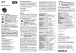
The picture below shows the BARTH® Mini-PLC STG-650
CAN with additional accessory, included in the STA-650
Starter-Kit (Art. No. 0660-0650).
The STG-650 CAN (Art. No. 0850-0650) comes without
USB connection cable VK-16.
4.1
Features
• 6 analog Inputs 0..30 VDC, 12 bit ADC
• 4 digital Inputs up to 1 kHz
• 8 Power Outputs up to 1.5 A
• 1 Power PWM Output 2 A/1 to 10 kHz
• 1 CAN Interface
• Reliable Solid-State Outputs
• Fail Safe Oscillator
• Programmable Status LED
• TTL-232/USB Connection to PC
• Intuitive graphical Programming Capability
• Wide Operating Voltage Range 7..32 VDC
• Wide Operating Temp. Range -40..+60°C
• Ultraflat Housing, Height 10 mm
• Vibration resistant and rugged Sealing
• Engineered and manufactured in Germany
4.2
Applications
• Industrial Automation
• Building Automation
• Automotive and Maritime Technology
• Environmental Technology
• Light and Show Technology
4.3
General description
The innovative STG-650 extends the established BARTH®
Mini-PLC series with a additional model featuring a rugged
CAN interface with graphical programming capability. With
similar dimensions in comparison to the STG-600, the STG650 provides outstanding graphical programming at lowest
current consumption and the wellknown small form factor.
The CAN bus allows the user to connect a variety of network
components to the Mini-PLC, for example: displays, stepper motors or CAN sensors.
The STG-650 does not need any peripheral components to
operate. Both inputs and outputs features highly integrated
and rugged protection circuits to operate the Mini-PLC in
really harsh environment. These outstanding features open
up a variety of application fields in industrial, automotive
and 12/24V battery-powered applications.
The STG-650 is also available as customer-tailored OEM
version.
© 2014-2015 BARTH Elektronik GmbH | Im Depot 1-3 | D-49838 Lengerich | www.barth-elektronik.de
® BARTH is a registered trademark. All rights reserved.
9021-0009-A
BAR H
Elektronik GmbH
4.4
®
Mini-PLC
STG-650 CAN
Art. No. 0850-0650
CAN Programming with miCon-L
Without learning a difficult programming language the
BARTH® Mini-PLC can be easily programmed using simple and vivid graphical function blocks. This block design
meets graphical standards of the latest graphical programming languages.
The miCon-L software suite features (CAN) programming,
simulation and test in one unique software design tool. The
flexible programming option offers a variety of possibilities
in industrial, automotive and maritime applications.
MANUAL
5
INSTALLATION
5.1
Mounting
Page:
Document:
Date:
Revision:
3/8
9021-0009-A
20.11.2015
A
The Mini-PLC must be installed and wired
by a trained technician who knows and
complies with both the universally applicable engineering rules and the regulations and standards that apply in specific
cases.
Fastening the STG-650 follows using either the integrated
mounting holes for screws or the holes for cable ties. The
cable tie installation method is recommended for fastening
the STG-650 on wiring harness, tubes or other mechanical
parts. Take care to meet the environmental conditions
of the STG-650.
5.2
Wiring
5.2.1 Overview
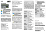
The graphic below shows the connection layout of the
BARTH® Mini-PLC STG-650 CAN.
Programming the STG-650 follows using the USB port
of your PC with installed miCon-L software suite and the
VK-16 USB Connection Cable. The miCon-L Software supports full simulation and visualisation operation modes.
miCon-L provides a variety of visualisation blocks and
interactive elements to control and debug the Mini-PLC.
X1 connector: supply and CAN pins
X2 connector: PLC inputs
X3 connector: PLC outputs
X4 connector: TTL-232/USB interface (VK-16)
For detailed information please read the BARTH® miCon-L
manual and the BARTH® Application Notes on:
www.barth-elektronik.de
4.5
Delivery content
• BARTH® Mini-PLC STG-650 CAN
• Spring terminal connectors (for supply, CAN, I/O)
© 2014-2015 BARTH Elektronik GmbH | Im Depot 1-3 | D-49838 Lengerich | www.barth-elektronik.de
® BARTH is a registered trademark. All rights reserved.
9021-0009-A
BAR H
Elektronik GmbH
®
Mini-PLC
STG-650 CAN
Art. No. 0850-0650
MANUAL
Page:
Document:
Date:
Revision:
4/8
9021-0009-A
20.11.2015
A
5.2.2 Connecting the power supply
5.2.4 Connecting the outputs
The STG-650 features an outstanding wide supply voltage
range from 7 to 32 VDC at lowest current consumption.
So the Mini-PLC can be integrated within battery supplied
12V or 24V DC systems (cars, trucks, battery powered cars,
forklifts and digger, for example).
Depending on load type and current the STG-650 is able
to drive electric loads directly without any additional driver
or protection circuit. The Mini-PLC provides 8 digital solidstate highside outputs and 1 solid-state lowside switch with
PWM functionality.
Turn off the power supply before performing any wiring operations!
False electrical connection, voltage
reversal or disregarding the electrical
specifications may cause irreversible
damage of the Mini-PLC!
Connect the supply voltage of 7 to 32 VDC to the 4-pole
terminal X1 of the STG-650. Wire the positive supply to the
‚+VDD‘ marked connection. The negative (ground) will be
wired to the ‚GND‘ connection. All terminals are carried out
as plugable spring terminal connectors for a wire gauge of
0.25 to 1.5mm².
Ensure correct power supply voltage
range and polarisation! External fusing of
5A max. is mandatory! Disregarding may
cause irreversible damage of the PLC!
5.2.3 Connecting the inputs
You can connect sensors, switches or buttons to the inputs.
The sensors may be temperature, flow, pressure, photoelectric sensors or proximity switches, for example.
The STG-650 is well suitable for any sensor featuring a voltage output, 0 to 10 VDC, for example.
Common features of the inputs
• IN1 to IN6 are selectable analog/digital inputs
• IN7 and IN10 are pure digital inputs (up to 1kHz)
• Wide input voltage range 0 to 32VDC
• IN1 to IN6 are 0 to 10 V compatible
• Comprehensive integrated protection circuits
• Outstanding electromagnetic compatibility (EMC)
• Electrostatic discharge protection (ESD)
Due to the pull-down resistors integrated in the STG-650
any switch (NO/NC) can simply be connected between the
positive supply (VDD) of the STG-650 and the desired input.
The voltage at any input must not exceed
32VDC referred to ground (GND).
Higher voltages or reverse voltage lower
than -32VDC may cause irreversible
damage of the Mini-PLC!
The 10-pole connector named X2 contains the inputs of the
Mini-PLC. While IN7 to IN10 are pure digital inputs, IN1 to
IN6 provide both digital or analog functionality. The voltage
range for all inputs may not exceed 32 VDC. All inputs refer
to GND. Please refer to the appendix for detailed electrical
specification of the inputs.
Common features of outputs OUT1 to OUT8
• Rugged solid-state higside switch up to 1.5A
• Paralleling permissible up to 6A
• Short circuit protection and current limitation
• Fast demagnetization of inductive loads
• Stable behaviour at undervoltage
• Comprehensive integrated protection circuits
• Outstanding electromagnetic compatibility (EMC)
• Electrostatic discharge protection (ESD)
Features of output OUT5
• Solid state lowside switch with PWM capability
• Sinks up to 2A
• Rugged solid-state design
• Fast demagnetization of inductive loads
• Outstanding electromagnetic compatibility (EMC)
• Electrostatic discharge protection (ESD)
The 9-pole connector X3 contains the digital outputs of
the Mini-PLC. While OUT1 to OUT8 are overload-protected
highside switches, OUT9 is carried out as lowside switch
with PWM capability without short circuit protection. A logical HIGH within miConL will switch the Mini-PLS´s supply
voltage at OUT1 to OUT8, while OUT9 switches lowside
(GND). Aviod a sink current exceeding 2A at OUT9 because
this outputs is not protected against short-circuiting or
overload current !
The total current sourced by OUT1 to
OUT8 must not exceed 6A!
Avoid reverse voltage at any output higher
than the Mini-PLC´s supply voltage!
OUT9 provides NO short circuit protection.
Take care the sink current not exceeds 2A!
Negligence may cause irreversible
damage of the Mini-PLC!
Please refer to the appendix for detailed electrical specification of the outputs.
5.2.5 Connecting the CAN interface
The X1 connector of the STG-650 contains the CAN specific
‚CANH‘ and ‚CANL‘ pins.
The voltage at CANH or CANL must not
exceed -27 or +40 VDC referred to ground
(GND). Higher voltages may cause irreversible damage of the Mini-PLC!
Please refer to the appendix for detailed electrical specification of the CAN interface.
© 2014-2015 BARTH Elektronik GmbH | Im Depot 1-3 | D-49838 Lengerich | www.barth-elektronik.de
® BARTH is a registered trademark. All rights reserved.
9021-0009-A
BAR H
Elektronik GmbH
6
6.1
®
Mini-PLC
STG-650 CAN
Art. No. 0850-0650
MANUAL
Page:
Document:
Date:
Revision:
5/8
9021-0009-A
20.11.2015
A
OPERATION AND PROGRAMMING
6.5
Software download
Establish the PC connection using the VK-16 connection
cable and run miConL. For choosing the correct virtual
COM-Port please click the right button (configure serial
interface) located on the main menu page and confirm the
added virtual COM-Port used by the STG-650.
BARTH supplies a free software license download package
for Microsoft® WINDOWS® which includes:
®
• Virtual COM port driver for USB connection
• miCon-L Software Suite
• Sample Programs for BARTH® Mini-PLC
First steps in miCon-L
Please download this package from:
www.barth-elektronik.de/download/9045-0008-A.zip
6.2
Virtual COM port driver installation
Before you connect the Mini-PLC to the PC you have to install the USB-/COM-port driver (folder ‚USBdriver‘) from the
software download package. Please follow the instructions
of the SETUP routine.
6.3
miCon-L Software Installation
Now install the miConL software suite from the ‚miCon-L‘
folder. Select your language file and follow the setup instructions of miConL.
6.4
Connecting the Mini-PLC
To operate the STG-650, first establish proper power supply
connection to the X1 connector.
Now start miConL with creating a new project (Project->
New) or open a miCon-L sample application (Project>Open).
For programming and PC connection the USB connection
cable VK-16 (Art. No. 0091-0010) and a PC with installed
Windows operating system are mandatory.
For Mini-PLC connection please use the X4 terminal. Take
care that the tappet of the 3-way VK-16 connector shows to
right direction of the STG-650 (black square).
Reversal connection only causes
malfunction and no damage of the
Mini-PLC.
© 2014-2015 BARTH Elektronik GmbH | Im Depot 1-3 | D-49838 Lengerich | www.barth-elektronik.de
® BARTH is a registered trademark. All rights reserved.
9021-0009-A
BAR H
Elektronik GmbH
®
Mini-PLC
STG-650 CAN
Art. No. 0850-0650
Creating a new project the desired Mini-PLC model and the
project name have to be defined. After opening or creating
a project the workspace of miConL with it´s libraries (right)
is shown.
Additional help and a detailed user manual is provided
within the miCon-L help and the miConL context menu
(right mouse button).
MANUAL
Page:
Document:
Date:
Revision:
6/8
9021-0009-A
20.11.2015
A
You can find sample programs in the ‚SAMPLE_PROGS‘
folder which is part of the miCon-L download package.
For detailed information and help please have a closer look
at the documents related to the miCon-L Software Suite:
http://www.barth-elektronik.de/micon-l-for-mini-plc-download-a2729.html
© 2014-2015 BARTH Elektronik GmbH | Im Depot 1-3 | D-49838 Lengerich | www.barth-elektronik.de
® BARTH is a registered trademark. All rights reserved.
9021-0009-A
BAR H
®
Elektronik GmbH
Mini-PLC
STG-650 CAN
Art. No. 0850-0650
7
APPENDIX
7.1
Specifications
Programming
Interfaces
MANUAL
Number digital
Number PWM
Output OUT1 - OUT8
BARTH® Mini-PLC
fully enclosed in proprietary PU
resin, tiny and rugged housing
with plugable spring terminal
connectors, ultra-lightweight
miCon-L Software,
graphical (function block style),
simulation, (CAN) programming
and visualisation, free license
TTL-232 (5V TTL level)
ITOT<= 6 A (paralleling permissible)
Maximal allowable load
inductance for a single switch off
(one output):
VDD=12VDC, IL=1.5A, ZL<=70mH
VDD=12VDC, IL=1A, ZL<=200mH
On-state resistance VDD to OUT:
RON<=180 mOhm
CAN (layer 2)
7.1.2 Power supply
Fusing
Voltage reversal protection
ESD/TVS protection
Heat dissipation air
(at full load)
7 to 32 VDC
nominal 15 mA at 32 VDC
(depending on configuration)
8 A max. (external)
mandatory for voltage reversal
protection
yes
(combined with external fuse)
yes
normally < 2.5 W
PWM output OUT9
Turn-on time: tON<=250 µs
Turn-off time: tOFF<=270 µs
Output type: solid state (lowside)
Potential isolation
IOUT <= 2 A (resistive load)
@ fOUT = 1 kHz to 10 kHz
IOUT <= 1 A (resistive load)
no
7.1.5 CAN interface
CAN
Analog input IN1 - IN6
Accuracy ADC
IN1 - IN6
ADC resolution
(internal)
Potential isolation
ESD/TVS protection
Permissible cable lenght
(per input)
CAN 2.0A:
11 bit ID, base frame format
CAN 2.0B:
29 bit ID, extended frame format
Baud rate:
100, 125, 250, 500 kbit
7.1.3 Inputs
Number digital
Number analog
Digital input IN7 - IN10
8+1
1
Output type: solid state (highside)
IOUT <= 1.5 A (resistive load)
@ fOUT = 0 to 100 Hz
UOUT >= UIN-0,45 V
USB (VK-16 required)
reserved for miCon-L software
communication
Operating voltage
Current consumption
7/8
9021-0009-A
20.11.2015
A
7.1.4 Outputs
7.1.1 General
Hardware design
Page:
Document:
Date:
Revision:
4+6
6
UIN = 0..30 VDC
RIN > 30 kOhm
ULOW <= 2 VDC
UHIGH > =4VDC
fIN <= 1 kHz
tIN >= 1 ms
UIN = 0..30 VDC
RIN > 11 kOhm
fIN <= 100Hz
tIN >= 10 ms
± 1% (<0.25 VDC)
12 Bit
no (common GND)
yes
normally 40 m
Meets or exceeds the requirements of applications ISO
11898-2, loss of ground
protection from –27 V to 40 V,
thermal shutdown protection
7.1.6 Security features
Security Features
Watchdog (WD)
Fail safe oscillator 16 MHz (FSO)
Brown out detection (BOD)
Power up timer (PUT)
7.1.7 Program and data memory
Flash program memory
EEPROM data memory
© 2014-2015 BARTH Elektronik GmbH | Im Depot 1-3 | D-49838 Lengerich | www.barth-elektronik.de
® BARTH is a registered trademark. All rights reserved.
64 k
cell endurance: 10.000 min
characteristic retention: 40 yrs
1024 byte
byte endurance 100.000 min.
characteristic retention: 40 yrs
9021-0009-A
BAR H
®
Elektronik GmbH
Mini-PLC
STG-650 CAN
Art. No. 0850-0650
7.1.8 Timebase (oscillator)
Primary Oscillator
Nominal Frequency
Frequency tolerance
Frequency aging
Second Fail Safe Oscillator
Crystal quartz MEMS unit
(precise ‚micro-electro-mechanical system‘)
16.000 MHz
±50 × 10-6
±5 × 10⁻⁶ / year max.
16 MHz
7.1.9 Electrical connection
Electrical Connection
plugable spring terminal
connectors 0.25 to 1.5 mm²
Manufacturer: Phoenix Contact
Series: COMBICON
Type: FMC1,5/x-ST-3,5
MANUAL
Electrostatic discharge
(ESD) on OUT1 to OUT9
Electrostatic discharge
(ESD) on CAN pins
Electromagnetic fields
20 kV air discharge
30 kV contact discharge
(IEC/EN 61 000-4-2, level 3)
8 kV (human body model)
(MIL-STD883D)
ESD Protection up to ±12 kV
(Human-Body Model)
Field strength 10 V/m
(IEC/EN 61000-4-3)
7.1.11 Environmental conditions
Operation temperature
Storage temperature
Relative humidity
Air pressure (in operation)
Shock resistance
Vibration resistance
Degree of protection
Drop
Free fall (packaged)
-40..+60 °C
(IEC 60068-2-1/2)
-40..+70 °C
(IEC 60068-2-1/2)
5 to 95% non-condensing
(IEC 60068-2-30)
500 to 1500 hPa
min. 100 m/s²
(IEC 60068-2-27)
min. 50 m/s² @ 10..150 Hz
(IEC 60068-2-6)
IP 20, limited by connectors
(EN 50178, IEC 60529)
Drop height: 500mm
(IEC 60068-2-31)
1500 mm
(IEC 60068-2-32)
7.1.12 Weight and dimensions
Weight
Dimensions
Mounting
80 g
(without connectors)
93 x 45 x 15 mm (LxWxH)
Height housing: 10 mm
via two M4 screws or 3.6mm
cable ties
8/8
9021-0009-A
20.11.2015
A
7.1.13 Ordering information
Ordering information
Mini-PLC
Ordering information
Starter-Kit
Ordering information
accessory
7.2
Mini-PLC STG-650
Art. No. 0850-0650
Starter-Kit STA-650
Art. No. 0660-0650
USB connection cable VK-16
Art. No. 0091-0016
Documents, videos and software
Detailed information, additional documents, application
notes and videos relating to this product are downloadable
from www.barth-elektronik.de and www.micon-l.de
7.3
Disposal
If you wish to finally dispose of the
product, ask your local recycling centre
or dealer for details about how to do
this in accordance with the applicable
disposal regulations.
7.1.10 Electromagnetic compatibility (EMC)
Electrostatic discharge
(ESD) on IN1 to IN10
Page:
Document:
Date:
Revision:
7.4
Conformity declaration
For the following designated product it is hereby confirmed,
that the construction in that technical design brought by us
in traffic corresponds to the standards specified below. In
the event of any alternation which has not been approved
by us being made to any device as designated below, this
statement shall thereby be made invalid.
Description
Type
Art. No.
Directive
2004/108/EG relating toelectromagnetic
compatibility (EMC)
Mini-PLC
STG-650
0850-0650
Applied norms:
EN55022:2006+A1:2007
EN55024:1998+A1:2001
+A2:2003
EN61000-3-2:2006
+A1:2009+A2:2009
EN61000-3-3:2008
EN61000-6-2:2005
RoHS Directive
2011/65EU
We herby declare that our
product is compilant to the RoHS
Directive on restriction of the use
of certain hazardous substances
in electrical and electronic appliances.
BARTH® Elektronik GmbH
Lengerich, 17.09.2015
Dipl.-Ing. (FH) D. Barth
Managing Director
© 2014-2015 BARTH Elektronik GmbH | Im Depot 1-3 | D-49838 Lengerich | www.barth-elektronik.de
® BARTH is a registered trademark. All rights reserved.
9021-0009-A