1
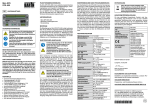
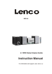
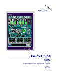
Mini-SPS
STG-500
BAR H
®
Elektronik GmbH
DE
KURZANLEITUNG
FUNKTIONSBESCHREIBUNG
Die Mini-SPS STG-500 ist eine grafisch programmierbare
universelle Kleinsteuerung mit 2 Digitaleingängen, 3 Analogeingängen und insgesamt 5 digitalen Ausgängen.
Die Programmierung erfolgt über die Software miConL,
die von BARTH frei zur Verfügung gestellt wird. Dabei
wird die Mini-SPS über den USB-Port an einen PC mit
Windows-Betriebssystem angeschlossen.
LIEFERUMFANG
•Mini-SPS STG-500
•Steckbare Federzugklemmen
•Kurzanleitung
MONTAGE
SICHERHEITSHINWEISE
Der Anschluss und die Inbetriebnahme der
Mini-SPS dürfen nur durch qualifiziertes
Personal unter Beachtung dieser Anleitung
erfolgen!
Schalten Sie die Anlage sowie die MiniSPS an der Sie arbeiten spannungsfrei
und sichern Sie diese gegen unbefugtes
Wiedereinschalten!
Lesen Sie aufmerksam diese Anleitung und
beachten Sie alle Sicherheits- und Warnhinweise!
BESTIMMUNGSGEMÄSSER GEBRAUCH
Die Mini-SPS STG-500 ist für den allgemeinen messund regeltechnischen Einsatz in nicht lebenserhaltenden, medizinischen oder sicherheitsrelevanten
Anwendungen konzipiert.
HAFTUNGSAUSSCHLUSS
BARTH übernimmt keine Gewähr für die Einsatz- und
Funktionsfähigkeit der Mini-SPS, wenn von dieser
Anleitung abgewichen wird. Da die Einhaltung dieser
Anleitung und der Bedingungen und Methoden der
Installation, des Anschlusses, dem Betrieb, der Verwendung und der Wartung der Mini-SPS von BARTH
nicht kontrolliert oder überwacht werden kann, übernimmt BARTH keine Haftung für daraus resultierende
Schäden.
MERKMALE
•Universell einsetzbare Kleinsteuerung
•3 Analogeingänge 0..30 VDC
•2 Digitaleingänge bis 10 kHz
•4 verschleißfreie Power-Ausgänge je 1,5 A
•1 Power-PWM-Ausgang 2 A/1..5 kHz
•Verschleißfreie Solid-State Ausgänge
•Programmierbare Status-LED
•RS232-Anschluss für PC
•Integrierter Temperatursensor
•Grafisch und intuitiv programmierbar
•Großer Betriebsspannungsbereich 7..32 VDC
•Großer Temperaturbereich von -40..+70°C
•Robust und vibrationsfest durch 2K-Verguss
•Sehr geringe Ruhestromaufnahme
•Universelle Alu-Montageplatte
Die Befestigung der Mini-SPS STG-500 erfolgt wahlweise über die in der Bodenplatte integrierten Öffnungen
mit Schrauben oder Kabelbindern. Die Montage mittels
Kabelbinder eignet sich insbesondere für die Befestigung
an runden Objekten wie z.B. Kabelbäumen oder Rohren.
ELEKTRISCHER ANSCHLUSS
Schalten Sie die Anlage an der Sie arbeiten
sowie die Mini-SPS spannungsfrei und
sichern Sie diese gegen unbefugtes
Wiedereinschalten.
Falschanschluss, Verpolung oder die
Nichteinhaltung der elektrischen Spezifikationen können die Mini-SPS irreversibel
zerstören.
Beim elektrischen Anschluss orientieren Sie sich bitte
an dem Aufdruck der Mini-SPS. Alle Klemmen sind als
steckbare Federzugklemmen für den Querschnittsbereich von 0,25 bis 1,5mm² ausgelegt. Die elektrischen
Spezifikationen der Ein- und Ausgänge entnehmen Sie
bitte den technischen Daten der folgenden Tabelle. Die
Spannungsversorgung der STG-500 erfolgt über den
2-poligen Steckverbinder „+VDD“ und „GND“. Die zulässige Betriebsspannung liegt im Bereich von 7 bis 32 VDC.
Beachten Sie die korrekte Polung der
Versorgungsspannung sowie eine externe
Absicherung bis maximal 5 A mittels Feinsicherung. Missachtung kann zur Zerstörung der Mini-SPS führen.
Der 10-polige Steckverbinder „IN1“ bis „IN5“ und „OUT1“
bis „OUT5“ beinhaltet die analogen und digitalen Eingänge sowie die digitalen Ausgänge der Mini-SPS.
IN1 und IN2 sind als reine Digitaleingänge ausgelegt sind.
Die Eingänge IN3 bis IN5 können sowohl digital als auch
analog im Bereich von 0 bis 30 VDC genutzt werden.
OUT1 bis OUT4 sind digitale plusschaltende Ausgänge
der Mini-SPS. Bei logischem HIGH wird die Versorgungsspannung der Mini-SPS auf den jeweils aktivierten Ausgang geschaltet. OUT5 ist ein masseschaltender Ausgang
mit PWM-Funktionalität. Dieser Ausgang verfügt über keinen Kurzschlussschutz!
INBETRIEBNAHME UND PROGRAMMIERUNG
Zur Inbetriebnahme der Mini-SPS muss die Versorgungsspannung an +VDD und GND angeschlossen sein. Für die
Programmierung benötigen Sie das Verbindungskabel
VK-10 (Art.-Nr. 0091-0010) und einen PC mit Windows-
Betriebssystem sowie RS232-Schnittstelle. Sollte Ihr
PC über keine RS232-Schnittstelle verfügen, so ist ein
USB/RS232-Adapter zu verwenden (z.B. BARTH Art.-Nr.
0208-0012). Installieren Sie nun die Software miCon-L
aus dem Ordner „miCon-L“ des Downloadpaketes (www.
barth-elektronik.de/download/9045-0008-A.zip). Folgen
Sie dabei den Anweisungen der Software. Im Anschluss
an die Installation verbinden Sie die Mini-SPS mit dem
PC und starten die Software miConL. Wählen Sie nun im
rechten Startbildschirm die korrekte COM-Schnittstelle
aus und bestätigen Sie diese. Anschließend starten Sie
die miConL-Anwendung und beginnen die Programmierung mit einem neuen Projekt. Eine ausführliche Anleitung
zu miConL erhalten sie über die Hilfefunktion der Software.
TECHNISCHE DATEN
ENTSORGUNG
Wenn Sie das Produkt endgültig außer
Betrieb nehmen, informieren Sie sich bitte
beim nächsten Recyclingcenter oder bei
Ihrem Fachhändler über die zutreffenden
Entsorgungsvorschriften.
EG-KONFORMITÄTSERKLÄRUNG
Für das nachfolgend bezeichnete Produkt wird hiermit bestätigt, dass die Bauart in der von uns in Verkehr
gebrachten Ausführung den unten genannten Normen
entspricht. Bei einer nicht mit uns abgestimmten Änderung des Produkts oder des Verwendungszwecks verliert
diese Erklärung Ihre Gültigkeit.
Bezeichnung
Mini-SPS
Betriebsspannung
7..32 VDC
Typ
STG-500
Stromaufnahme
< 4 mA bei 32 VDC
(ohne eingeschaltete StatusLED)
Art.-Nr.
0850-0500
Richtlinie
2004/108/EG über die
elektromagnetische
Verträglichkeit (EMV)
Angewandte Normen:
EN55022:2006+A1:2007
EN55024:1998+A1:2001
+A2:2003
EN61000-3-2:2006
+A1:2009+A2:2009
EN61000-3-3:2008
EN61000-6-2:2005
RoHS-Richtlinie
2011/65EU
Hiermit bestätigen wir die
Konformität des oben
genannten Produktes entsprechend der Richtlinie zur
Beschränkung der Verwendung gefährlicher Stoffe in
Elektro- und Elektronikgeräten.
Absicherung
5 A max. (extern)
Digitaleingang
IN1 - IN2
UIN = 0..30 VDC
RIN > 30 kOhm
ULOW <= 5 VDC, UHIGH > 5VDC
fIN <= 1 kHz, tIN >= 1 ms
Analogeingang
IN3 - IN5
UIN = 0..30 VDC
RIN > 11 kOhm
Genauigkeit ADC
IN3 - IN5
± 3% (0,5 VDC) @ 25°C
Auflösung 10 Bit
Ausgang
OUT1 - OUT4
IOUT <= 1,5 A (ohmsche Last)
@ fOUT = 0..100 Hz
UOUT >= UIN-0,45 V
ITOT<= 4 A
PWM-Ausgang OUT5
IOUT <= 2 A (ohmsche Last)
@ fOUT = 0..100 Hz
IOUT <= 1 A (ohmsche Last)
@ fOUT = 100 Hz..5 kHz
UOUT <= GND+0,25 V
BARTH® Elektronik GmbH
Lengerich, 10.11.2014
Sicherheit
Watchdog (WD)
Brown out detection (BOD)
Power up timer (PUT)
Elektrischer Anschluss
Steckbare Federzugklemmen
0,25..1,5 mm²
Betriebsumgebungstemperatur
-40..+70 °C (IEC 60068-2-1/2)
DOKUMENTE UND SOFTWARE
Lagertemperatur
-40..+70 °C (IEC 60068-2-1/2)
Detaillierte und ergänzende Dokumente zu diesem Produkt erhalten Sie auf unserer Internetseite
Schockfestigkeit
min. 100 m/s² (10G)
Vibrationsfestigkeit
min. 50 m/s² (5G)
@ 9..200 Hz
Schutzart
IP 20
Gewicht
50 g (ohne Steckverbinder)
Abmessungen
40 x 40 x 22 mm (LxBxH)
(ohne Steckverbinder)
Bestellinformation
Mini-SPS
Mini-SPS STG-500
Art.-Nr. 0850-0500
Bestellinformation
Zubehör
Verbindungskabel VK-10
Art.-Nr. 0091-0010
Adapter RS-232 <-> USB
Art.-Nr. 0208-0012
Dipl.-Ing. (FH) D. Barth
Geschäftsführer
www.barth-elektronik.de
Programmier- und Simulationssoftware miCon-L
www.barth-elektronik.de/download/9045-0008-A.zip
BARTH® Elektronik GmbH | D-49838 Lengerich
Tel. +49 (0)5904 964545 | Fax +49 (0)5904 964546
www.barth-elektronik.de | [email protected]
Dokument Nr. 9078-0004-A | Ausgabe 06.01.2015
©® 2014. Alle Rechte und Änderungen vorbehalten.
9078-0004-A
Mini-PLC
STG-500
BAR H
®
Elektronik GmbH
EN
QUICK START MANUAL
FUNCTION DESCRIPTION
The Mini-PLC STG-500 is a fully graphical programmable
logic controller providing 2 digital inputs, 3 analog inputs
and 5 outputs. The free miCon-L software suite features
intuitive graphical programming and debugging capability
using vivid function blocks via USB port and a common
Windows PC.
DELIVERY CONTENT
•Mini-PLC STG-500
•Plugable spring terminal connectors
•Quick start manual
INSTALLATION
SAFETY INSTRUCTIONS
Persons trained in the local and national
electrical standards must perform all tasks
associated with wiring the Mini-PLC.
Turn off the power supply before performing any wiring operations!
Short circuits can be harmful, critical and
can cause explosions and serious burns!
Please read this manual carefully and
observe all safety instructions!
DESTINATED USE
The Mini-PLC STG-500 is designed for universal
measuring, controlling and regulating applications.
It may not be used for life critical, medical or fail safe
applications.
DISCLAIMER
BARTH Elektronik GmbH assumes no liability for
usage and functionality of the STG-500 in case of disregarding this manual. The strict accordance of this
manual is important since the installation methods,
peripheral connections, usage and maintenance can
not be controlled by BARTH Elektronik GmbH. Therefore BARTH Elektronik GmbH assumes no liability for
any claim.
FEATURES
•Small and universal PLC
•3 analog Inputs 0..30 VDC
•2 digital Inputs up to 10 kHz
•4 Power Outputs up to 1.5 A
•1 Power PWM Output 2 A/1..5 kHz
•Reliable Solid-State Outputs
•Programmable Status LED
•RS232 Connection to PC
•Integrated Temperature Sensor
•Intuitive graphical Programming Capability
•Wide Operating Voltage Range 7..32 VDC
•Wide Operating Temp. Range -40..+70°C
•Vibration resistant and rugged Sealing
•Very low Current Consumption
•Universal Aluminium Mounting Plate
Fastening the STG-500 follows using either the integrated
mounting holes for screws or the holes for cable ties. The
cable tie installation method is recommended for fastening the STG-500 on wiring harness or tubes.
the ‚miCon-L‘ folder of the software download package
(www.barth-elektronik.de/download/9045-0008-A.zip).
Follow the setup instructions of miConL. Afterwards establish the PC conntection and start miConL. For choosing
the correct COM-Port please click the right button loacated on the main menu page and confirm the added COMPort used by the STG-500.
Now start miConL with opening a new project choosing
the device ‚STG-500/501‘. Additional help and a detailed
user manual is provided within the miCon-L help and the
miConL context menu (right mouse button).
SPECIFICATIONS
False electrical connection, voltage
reversal or disregarding the electrical
specifications may cause irreversible
damage of the Mini-PLC!
For electrical connection please refer to the information
printed on the Mini-PLC´s housing. All terminals are carried out as plugable spring terminal connectors for a wire
gauge of 0.25 to 1.5mm². For electrical input and output
specifications please refer to the following table. Connect
the supply voltage of 7 to 32 VDC to the 2-pole terminal
‚+VDD‘ and ‚GND‘ of the STG-500.
Ensure correct power supply voltage range
and polarisation! External fusing of 5 A
max. is mandatory! Disregard may cause
irreversible damage of the Mini-PLC!
The 10-pole connector named ‚IN1‘ to ‚IN5‘ and ‚OUT1‘ to
‚OUT5‘ contains all inputs and outputs of the Mini-PLC.
While IN1 und IN2 are pure digital inputs, IN3 to IN5 provide both digital or analog functionality. The voltage range
for all inputs may not exceed 30 VDC.
The terminals OUT1 to OUT9 contains the digital outputs
of the Mini-PLC. While OUT1 to OUT4 are overload-protected highside switches, OUT5 is carried out as lowside switch with PWM capability without short circuit
protection. A logical HIGH within miConL will switch the
Mini-PLS´s supply voltage at OUT1 to OUT4, while OUT5
switches lowside (GND). Aviod a sink current exceeding
2A at OUT5 because this outputs is not protected against
short-circuiting or overload current!
OPERATION AND PROGRAMMING
To operate the STG-500, ensure proper power supply
connection at both +VDD and GND terminals. For programming and PC connection use the Connection Cable
VK-10 (Art. No. 0091-0010). A PC with installed Windows
operating system and RS232 interface is mandatory. In
case your PC is not equipped with an RS232 interface
you have to use an USB/RS232-Adapter (BARTH Art. No.
0208-0012). Now install the miConL software suite from
If you wish to finally dispose of the
product, ask your local recycling centre or
dealer for details about how to do this in
accordance with the applicable disposal
regulations.
EC CONFORMITY DECLARATION
For the following designated product it is hereby confirmed, that the construction in that technical design
brought by us in traffic corresponds to the standards specified below. In the event of any alternation which has not
been approved by us being made to any device as designated below, this statement shall thereby be made invalid.
Operating Voltage
7..32 VDC
Current Consumption
< 4 mA at 32 VDC
(Status-LED switched off)
Description
Mini-PLC
Fusing
5 A max. (external)
Type
STG-500
Digital Input
IN1 - IN2
UIN = 0..30 VDC
RIN > 30 kOhm
ULOW <= 5 VDC, UHIGH > 5VDC
fIN <= 1 kHz, tIN >= 1 ms
Art. No.
0850-0500
Analog Input
IN3 - IN5
UIN = 0..30 VDC
RIN > 11 kOhm
Directive
2004/108/EG relating
toelectromagnetic
compatibility (EMC)
Accuracy ADC
IN3 - IN5
± 3% (0.5 VDC) @ 25°C
Resolution 10 Bit
Ausgang
OUT1 - OUT4
IOUT <= 1,5 A (resistive load)
@ fOUT = 0..100 Hz
UOUT >= UIN-0,45 V
ITOT<= 4 A
Applied norms:
EN55022:2006+A1:2007
EN55024:1998+A1:2001
+A2:2003
EN61000-3-2:2006
+A1:2009+A2:2009
EN61000-3-3:2008
EN61000-6-2:2005
RoHS Directive
2011/65EU
PWM Output OUT5
IOUT <= 2 A (resistive load)
@ fOUT = 0..100 Hz
IOUT <= 1 A (resistive load)
@ fOUT = 100 Hz..5 kHz
UOUT <= GND+0,25 V
We herby declare that our
product is compilant to the
RoHS Directive on restriction
of the use of certain hazardous substances in electrical
and electronic appliances.
Security Features
Watchdog (WD)
Brown out detection (BOD)
Power up timer (PUT)
Electrical Connection
plugable spring terminal
connectors 0.25 to 1.5 mm²
ELECTRICAL CONNECTION
Turn off the power supply before performing any wiring operations!
DISPOSAL
Operation Temperature -40..+70 °C (IEC 60068-2-1/2)
BARTH® Elektronik GmbH
Lengerich, 10.11.2014
Dipl.-Ing. (FH) D. Barth
Managing Director
Storage Temperature
-40..+70 °C (IEC 60068-2-1/2)
Shock Resistance
min. 100 m/s² (10G)
DOCUMENTS AND SOFTWARE
Vibration Resistance
min. 50 m/s² (5G)
@ 9..200 Hz
Detailed information and additional documents relating
to this product are downloadable from
Protection Grade
IP 20
Weight
50 g (without connectors)
Dimensions
40 x 40 x 22 mm (LxWxH)
(without connectors)
Ordering Information
Mini-PLC
Mini-PLC STG-500
Art. No. 0850-0500
Ordering Information
Accessory
Connection Cable VK-10
Art. No. 0091-0010
Adapter RS-232 <-> USB
Art. No. 0208-0012
www.barth-elektronik.de
Programming and Simulation Software miCon-L
www.barth-elektronik.de/download/9045-0008-A.zip
BARTH® Elektronik GmbH | D-49838 Lengerich
Tel. +49 (0)5904 964545 | Fax +49 (0)5904 964546
www.barth-elektronik.de | [email protected]
Document No. 9078-0004-A | Edition 06.01.2015
©® 2014. All rights reserved.
9078-0004-A