1
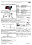
2. Package content
3. Features
This manual explains the features of your new
PRO II reader, the specifications and the
installation in a few simple steps.
4. Specifications
Please retain this guide for further reference.
5. Hardware setup
If you have questions regarding your PRO II
reader / writer, please call our technical support
hotline at toll free number
PRO II is a compact, light-weight and easy-to-install read /
write device for today's most common types of flash memory
cards. It brings you the convenience of data transferring
between your PC and other personal electronic devices, such
as digital camera, MP3 player, PDA, Voice recorder, Personal
organizers, Pocket PC and many more. With the versatile
design, PRO II can be used externally, or internally when
mounted into your PC's standard 3.5" drive bay.
1. For both internal (3.5" Drive Bay) and external use.
The flash memory cards support by PRO II reader/writer
includes:
3. Fast file transferring between portable Memory Card, PC,
Notebooks and Mobile devices, such as
- Digital Cameras,
- Pocket PC,
- Personal Digital Assistant (PDA),
- Personal Organizers,
- Voice Recorders, etc.
CF
MD
SD
MMC
SM
Type I/II CompactFlashTM card
IBM MicroDrive TM
Secured DigitalTM card
MultiMedia TMcard
SmartMediaTMcard
Plus one USB port on the front for easy access.
6. Software setup
Package Content
sales @power-win.com
www.power-win.com
2. Reads and Writes
-Type I and II Compact FlashTM cards
-IBM Microdrive TM
TM
-SmartMedia cards
-MultimediaTM cards
TM
-Secured Digital cards
Like mounting a 3.5" floppy drive to your PC, PRO II comes
with 3 screw holes on each side for position adjustment.
Insert PRO II into one of empty 3.5" external drive bay of
your PC, align the PRO II front panel evenly with the computer
front bezel and apply screws to secure it into the place.
Support :
Win 98 / SE/ ME/ 2000/ XP, Mac OS 8.6 or later, Linux.
Plug & Play for :
Windows ME/ XP ( no software driver required )
For internal cable connections, plug in the Internal USB cable
and power supply "Y" cable. Please refer to the following
diagram for connection to the PRO II .
Hardware Setup
Using PRO II externally
Internal
USB cable
Hardware setup is easy. Simply plug in the External USB
cable and DC to USB cable, your new PRO II reader/writer
is ready to operate. Please refer to the following diagram
for detail.
Dimension :
102(W) x 25.4(H) x125(D) mm / 4.02(W) x 1(H) x 4.92(D) in
Internal Power Supply "Y" cable
Power Required :
USB , IEEE 1394 port support.
_ 5%
Action power: 5V +
1x PRO II Flash reader / writer unit
1x External USB cable (External USB port to PRO II USB)
1x External DC-USB cable (External USB to PRO II DC Input)
1x Internal USB cable (Motherboard USB header to PRO II USB)
1x Internal Power Supply "Y" cable
(Power Supply Unit to PRO II Power Input)
or visit our web site at
Using PRO II internally
Download / Upload files via high speed IEEE1394 / FireWire
USB 1.1
IEEE 1394 transfer rate up to : 400Mb/Sec
USB 1.1 Transfer rate up to : 12Mb/Sec
Specifications
886-2-26983989
or e-mail us at
Folding Line
User's Manual
Features
Introduction
1. Introduction
Folding Line
Congratulations on the purchase of your new
Power-Win Technology Corp. PRO II flash reader/
writer. PRO II is a read / write device that
supports multiple types of flash memory cards
and we recommend you read this manual
carefully to become familiar with the operation
of the product.
USB MULTI-SLOT CARD READER/WRITER
Folding Line
Folding Line
Folding Line
Folding Line
P R O II
Table of Content
Due to certain motherboard USB headers have different pin
layouts, it is possible that user needs to reconfigure the wire
pin assignments on the internal USB cable, in order to make
PRO II function properly. Following explains how to
reconfigure wire pin assignment.
Reads and Writes : (Hot-swapping)
TM
Compact FlashTM , IBM MicrodriveTM , SmartMedia ,
TM
TM
Mutimedia , and Secure Digital cards
External
USB cable
POWER-WIN TECHNOLOGY CORP.
www.power-win.com
The Internal USB cable has 4 color wires on the end
that plugs in to the motherboard. The 4 color wires
are Red, White, Green and Black wires. The correct
wire assignments shall be:
Line
Line
Line
Line
Line
Line
External DC-USB cable
Folding Line
Folding Line
Folding Line
Folding Line
Folding Line
Folding Line
Software Setup
Windows ME and Windows XP or later
10. GND
8. GND
6. P+
4. P2. USB Power (or VCC or +5V)
Software Setup for PRO II under operating systems, like Windows
ME and Windows XP, is very simple . No software driver is required.
Here are the few steps:
If your motherboard USB header pin layout matches one of
the examples above, you will not need to reassign the wire
pins on the internal USB cable.
To remove Flash media cards from PRO II reader/writer
1. Double click on the “Removable Device” icon on the lower
right hand corner of your desktop.
2. You shall see a small icon appear on the lower right hand corner
of your desktop. (as shown below)
Click on “Finish”
(1) Determine the wires that you need to remove from the pin
connectors first by referring to your motherboard USB
header pin layout.
Example B
You will need to restart your computer, in order to complete your
installation. Please make sure that all of files are saved and it is
okay to restart the computer.
Click on “Next”
(2) Using a needle or push pin to flip up the tiny plastic tab
and pull the wire out from the connector. Please take
caution on this step as excessive force on flipping the tab
may cause the tab to break.
4. You Computer will notify you when it is safe to remove your
Flash card. Click on “OK” and remove the Flash card.
For Windows 2000
Prior to installation of PRO II reader/writer, please take following
steps to install device driver first, then proceed with the necessary
cable connections (as described in Hardware Setup), and reboot
the computer.
(4) Insert the wire pin back into the correct slot and press the
tiny plastic tab down will hold the wire in its position.
The diagram below shall give you an idea of how it is done.
Example A
Select “Yes, I want to restart my computer now” and click on “OK”
2. USB Power (or VCC or +5V)
4. P6. P+
8. GND
10. GND
Computer will restart and you can connect the cables from PRO II
reader/writer to your computer (as described in Hardware Setup)
after restart. Your computer shall recognize the Pro II unit
automatically and install its driver for it.
Line
Line
Click on “Yes” to accept the agreement and click on “Next”
Line
Example A
A software setup file can be downloaded from our web site:
http://www.power-win.com/drivers/pro2setup.exe
Line
2. A list of three "USB Disk” devices will appear. Select the one you
would like to remove and click on “Stop” button.
Windows 98, Windows 98 SE and Windows 2000
(3) Repeat above steps for each wire that requires changing.
1. USB Power (or VCC or +5V)
3. P5. P+
7. GND
9. (Empty pin)
3. Click on “OK” when “Stop a Hardware device” menu pop up.
After complete installation, you shall find 3 "Removable Disk" icons
created in [My Computer]. Clicking on each Removable Disk will
give you the access to the flash cards you have inserted into
PRO II reader/writer slot.
1. Once you plug in the two external USB cables (as described in
Hardware Setup), your computer shall immediately recognize
the PRO II device and install all drivers automatically.
If your motherboard USB header pin layout does not match
the examples above, please take following steps to reassign
the wire pins on the internal USB cable.
Please refer to your motherboard manual or contact your
motherboard manufacturer for the USB header pin layout
information. Two of the most common layouts are as follow:
After downloading [pro2setup.exe], execute the file and it will
lead you into setup program.
Line
1. USB Power (or VCC or +5V)
3. P5. P+
7. GND
9. (Empty pin)
Line
Example B
Red = Power or VCC
White = P- or DataGreen = P+ or Data+
Black = Ground or GRND or GND