1
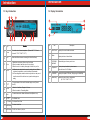
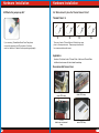
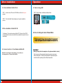
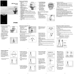
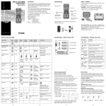
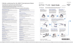
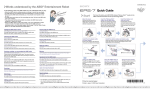
HARDCANO 13
Integrate the Intelligent Fan controller and 6 in 1 Card reader
Multi-function 5.25 " Drive bay
P/N:A2259
User's Manual
C 2003 Thermaltake Technology Co.,Ltd. All Rights Reserved.
REV. A 2004.08
All other registered trademarks belong to their respective companies.
Content
Part I - Introduction
1.1 Overview
P.01
1.2 Components check
P.01
1.3 Key Introduction
P.02
1.4 Display Introduction
P.03
Part II - Installation
2.1 How to Install in case
P.05
2.2 Connectors from Hardcano 13
P.06
2.3 How to Connect with 3pin Fan
P.07
2.4 How to Connect with 4pin Fan
P.08
2.5 What is the jumper cap for
P.10
2.6 Where should I place the Thermal sensor Probe
P.11
3.1 System Requirements
P.12
3.2 Driver Installation for Windows 98/SE
and Windows 2000
P.12
3.3 Hardware setup
P.13
3.4 Drive Installation for Mac OS 8.6
P.14
3.5 Drive Installation for Mac OS 10.X
P.14
Part III - Operation
4.1 How to change A/M
P.15
4.2 How to distinguish Auto / Manual Mode
P.15
4.3 How to set Fan Speed (only in manual mode)
P.17
4.4 How to set Alarm
P.18
4.5 How to change the Color of the LCD Panel
P.18
4.6 How to switch to Celsius or Fahrenheit
P.19
4.7 How to change Clock Display Mode
P.19
Part V - Q & A
P.21
Introduction
1.1 Overview
Hardcano 13 is a multi-functional media panel with Intelligent
Thermal Management System and Smart Card Reader.
The Intelligent Thermal Management System monitors
fan speeds,temperatures at 4 different locations in real-time
with "Thermal Alarm".The smart card reader supports 6
Part I
Components Check
popular Flash Memory Card formats:
CompactFlashTM, MicrodriveTM, Memory StickTM,
Memory Stick ProTM, Secure DigitalTM, MultiMedia CardTM,
and SmartMediaTM. No matter what, you can be sure that your
Data will be transferred to your computer safely and securely.
1.2 Components Check
User s' Manual x 1
Accessory Pack x 1
Hardcano 13 Module x 1
1
1
Introduction
Introduction
1.3 Key Introduction
1.4 Display Introduction
No .
Key
No.
Function
O
1
Alarm
To set the value of alarm temperature. (*Default: 40 C. ** Preset
O
O
O
O
Values: 40 C/ 50 C/60 C/ 70 C)
2
Fan
Switch the different channels circularly(Fan1/Fan2/Fan3/Fan4)
3
Color
1.Switch the color display / Return from Clock Mode
2.Press 4 seconds to start the cycle of 8 color display
3.When the color is in rotation, press again to fix the color you like.
4
21
Knob
1.At Manual mode, adjust the fan speed by rotating the knob. Rotate
clockwise for acceleration, counter clockwise for deceleration.
2.At Time setting Mode, rotate the knob to adjust the hour and press it
to set the minute. When the time is set, press the knob again as
ending.
5
O
To toggle between Celsius and Fahrenheit display mode. (Default:
Celsius)
6
Clock
1.Switch to Clock Mode. Display in 24 Hours.
2.Press 4 seconds to Time setting Mode.
7
A/M
To switch between Auto Mode and Manual Mode (Default: Auto)
8
9
SD/MMC
Socket
For SD/MMC Card
CF Socket
For Compact Flash Card
10
SM Socket
For Smart Media Card
11
MS Socket
For MS Card / Memory stick pro.
C/OF
Icon
Description
1
Fan1~Fan4
Displays the current location monitored.
2
Mode
Display the Auto or Manual Mode.
3
CF/SD/SM/
MS/MMC
Indicate the type of memory card in use.
4
Temp/clock
Display the temp feedback by thermal sensor
Show the time at CLOCK Mode.
5
XXXXRPM
Displays fan speed in RPM unit .(Display range 0~9999RPM)
6
Alarm temp.
Displays the value of alarm temperature
O
O
O
O
(40 C/ 50 C/60 C/ 70 C)
3
Hardware Installation
2.1 How to Install in case
STEP 1:
Connect the Fans
Connect the 3 pin connector of the fan directly to the
3 pin socket of Hardcano 13. If the cable length is not
long enough, use the 3pin extension adapter.
Some fan units uses 4 pin connector instead of 3 pin
connector. In this case, please use the 4pin to 3 pin
adapter provided in the package to connect it
to the 3pin socket of Hardcano 13.
STEP 2:
Part II
Installation
Connect the Thermal Sensor
Connect the 2 pin connector of thermal
sensor cable to the 2pin socket of Hardcano 13.
You may place the Thermal Sensor Probes to
different chassis locations.
STEP 3:
Install the Hardcano 13.
Secure the Hardcano 13 into any open
external 5.25" drive bay with the
screws provided in the package.
Note: Some PC chassis requires 5.25"
guide rails to be mounted on the
drive units in order to
slide into the drive bay.
STEP 4:
Connect the Power Cable
Connect the 4 pin MOLEX connector from computer
power supply to the 4pin socket of Hardcano 13.
STEP 5:
Install The Card Reader To Motherboard
Connect the USB signal cable to the USB
socket on Motherboard
Note: Please refer to your motherboard
manual for USB connectors.
41
5
Hardware Installation
Hardware Installation
2.2 Connectors from Hardcano 13
2.3 How to Connect with 3pin Fan
Fan Control Cable X 4
Connectors:
4pin
connector X1
Connectors:
thermal probe
X4
For power supply
Example
For CPU cooler
Example
For VGA cooler
Example
For case environment
Example
For power supply
Connectors:
3pin
connector
X4
Application:
Example
For CPU fan
Example
For VGA fan
Example
For case fan
Example
For power supply fan
Each set of Fan Control Cable is
labeled as followed:
Fan1/Fan2/Fan3/Fan4
Each can be connected to 3pin fan
connector.
Connecting Fans
Controller connection figure
Adaptor:
RPM (Speed)
Signal Connector
"Provide RPM
Signal Only,
Not Power"
61
Connect H13 Control Connector
+12V +5V 4pin Power Connector
Fan Control Connector
Above application shows Fan1 Fan Control Cable connected to a
most common fan connector. This setup will allow Hardcano 13 to
adjust fan speed and receive RPM signal as well.
71
Hardware Installation
Hardware Installation
2.4 How to Connect with 4pin Fan
Instruction
Connect to Hardcano 13
Some fan unit may be using 4pin connector. In order for
Hardcano 13 module to control, you'll need to utilize this included
adaptor.
Adaptor(3 pin to 4 pin) X 1
Using 3-pin to 4-pin Adapter
Connector
4pin Fan Connector
Connect the Hardcano
13 fan connector to the
the 3-pin adapter
Connect the 4-pin
Power connector to
4-pin adapter
Connect the RPM
Signal Connector to
the Fan Connector
Hardcano 13 Fan connector
Note:
A few variation of fans does not output RPM (Speed)
signal. Therefore, Hardcano 13 is unable to monitor
the RPM (Speed) of the fan, but it is still able to adjust
the RPM (Speed).
RPM (Speed) Signal Connector
"Provide RPM Signal Only, Not Power"
CPU Fan
81
CPU Fan
Case Fan
VGA card cooler
9
Hardware Installation
Hardware Installation
2.5 What is the jumper cap for?
2.6 Where should I place the Thermal Sensor Probe?
Thermal Probe X 4
T1
If you are using Thermaltake Smart Case Fan, please
connect the jumper to the VR connector of the fan in
order for Hardcano 13 detect the fan speed signal properly.
T2
T3
T4
There are 4 sets of Thermal Sensor Probe that you may
place in the computer case. Please see pictures below
for recommended monitor areas.
Application:
Hardcano 13 includes 4 sets of Thermal Probe. Attach each Thermal Probe
to different heat sources with the included thermal tape.
Recommended Sensor Area:
10
1
CPU cooler
detect CPU temp
VGA card cooler
detect VGA temp.
CPU fan
detect case environment
temp.
Power supply
detect PSU temp
11
Drive Installation
Drive Installation
3.1 System Requirements
3.3 Hardware setup
One of following operating systems:
- windows 98/ SE
- windows 2000
- Windows ME (No drive needed)
-Windows XP (No drive needed)
- Mac OS 8.6
- Mac OS 9.X
- Mac OS X 10.1.2(No drive needed)
STEP 1: The Windows will automatically recognize the Smart Card Reader
and it will continue installing files that is required for the Smart Card Reader.
STEP 2: The Smart Card Reader is ready to use! Please check there are four
new drives under "My Computer".
3.2 Driver Installation for Windows 98/SE and Windows 2000
STEP 1. Insert the driver CD into the CD-ROM drive. Run the program
Setup.exe.
STEP 2. The Install shield Wizard will guide you through the installation
process.
12
1
13
Drive Installation
Operation
3.4 Drive Installation for Mac OS 8.6
4.1 How to change A/M
STEP 1. Insert the driver CD into the CD-ROM drive. Run the Setup.exe
program.
STEP 1. Switch between Auto Mode and Manual Mode
STEP 2. The Install shield Wizard will guide you through the installation
process.
3.5 Drive Installation for Mac OS 10.X
The Hardcano 13 is a drive-free device for Mac OS 10.X and up. Mac OS 10.X
and up will detect the device and install all the associated files required for its use
automatically.
4.2 How to distinguish Auto / Manual Mode
While the computer is idling or under minor workload
workload,, it is recommended
to switch operating mode to Automatic to minimize the overall noise level.
3.6 How to Use the 6 in 1 Card Reader with Mac OS
When disk icon will appear on the desktop. You can then use
the storage card as if it were a Mac HardDisk.
14
Auto. Mode
(when you away from the computer or the system workload is minor )
Each fan's speed will be automatically adjusted according to each preset
location's temperature. Following chart represents the approximate speed
at which fan will be operating under at different temperature.
15
Operation
How to set Alarm Temp.
4.3 How to set Fan Speed (only in manual mode)
STEP 1. Select the Fan you wish to adjust by press "Fan button"
(12V)
(6V)
Press "Fan button"
(Environment Temp.)
(Alarm setting Temp.)
STEP 2. Rotate the Knob to increase and decrease fan speed. Rotate
clockwise for acceleration, counter clockwise for deceleration.
(Maximum speed varies from each different fan unit.)
Manual Mode
(when you are using the computer or the system workload is heavy )
While operating under Manual Mode, users may . adjust the fan speed by rotating
the knob. Rotate clockwise for acceleration, counter clockwise for deceleration.
Note : The range for the RPM signal display
Is 0 RPM to 9999 RPM.
16
17
1
Operation
Operation
4.4 How to set Alarm
4.6 How to switch to Celsius or Fahrenheit?
Press the "Alarm" bu tton repea tedly until your desired temperature is shown on
the LCD. (Default: 60OC)
STEP 1. Press switch button as shown on the picture below
EX. This display shows Alarm temp.
60OC at FAN/T1
Press the "Alarm" button
4.7 How to change Clock Display Mode
4.5 How to change the color of the LCD Panel?
STEP 1. Simply press "Color" Button as shown on the Picture Below.
Press 4 seconds to start the cycle of 8 color display
Deep Blue
Yellow
18
STEP 1. Press & Hold 4 seconds to set Time Mode as shown on the picture below.
Purple
Deep Green
Red
Light Green
Light Blue
White
STEP 2. Rotate the knob to adjust the hour and press it to set the minute. When the time
is set, press the knob again as ending.
19
1
FAQ
FAQ
5.1:The Hardcano 13 Module does not come on after system is
Powered?
Ans: Please make sure the main power connector is connected to
Power Supply.
Part III
Q&A
Slide the cover
towards back to
remove.
Make sure all
connectors are
connected securely.
5.2: LCD does not display temperature?
Ans:1.Make sure its corresponding Thermal Probe is attached
correctly to the component you wish to monitor.
2.Examine the Thermal Probe to see if there is any cut or
Discontinuity!
5.3: LCD does not display fan RPM?
Ans:1.Make sure the cables are connected securely.
2.Verify the fan unit you are controlling & monitoring has RPM
signal capability. Majority of the 3 wire fan have RPM signal
Capability, while 2 wire fans do not.
5.4: LCD screen seems to be a little dimmer after some usage?
Ans: After some time, LCD may not be as bright as initial use. This is
a normal characteristic for all LCD screen and will not affect
Hardcano 13's performance in any way.
20
21
1
FAQ
Company Information
5.5: Hardcano 13 unit is unable to adjust fan speed?
Ans: A portion of fan unit have built in fan speed control.
To allow Hardcano 13 to take control, certain steps need to be
Performed. ie. Insert jumper.
Taiwan : Thermaltake Technology Co.,Ltd.
Address: 8F, No.27, Lane 155, Sec.3, Pei Shen Road, Saen
Keng Hsiang, Taipei Hsiang, Taiwan
TEL:(886) 2-2662-6501 FAX:(886) 2-2662-6510
E-mail: [email protected]
Overseas Branch
USA: Thermaltake Technology Inc.
Address: 525Parritott Place,
City of Industry, CA 91746
TEL: (626)968-9189 FAX: (626)968-7659
E-mail: [email protected]
France: Thermaltake France
Address: 73, Bld de Courcerin Parc du Courcerin 77185 Lognes
TEL: + 33 - (0)160 1763 15 FAX: + 33 - (0)1 60 17 63 16
E-mail : [email protected]
China: Thermaltake Beijing Co.Ltd
Address: #1507,No.168,XiWai Street, Haidian District,
Beijing PRC 100044
TEL:+86 -10-88576268~70 FAX:+86-10-88576271
E-mail: [email protected]
Australia: Thermaltake Australia and
New Zealand Pty Ltd
Address: Unit 1, 49 Henderson Road Rowville
Victoria 3178 Australia
TEL: +61 (03) 9763 1622 FAX: +61 (03) 9763 1677
E-mail: [email protected]
URL: www.thermaltake.com.au
Japan: Thermaltake Japan Inc.
Address: No.5-A, Hei-An Bldg 2-6-16 Okubo,
Shinjuku-ku, Tokyo, 169-0072, Japan
TEL: +81 03-3203-3371 FAX: +81 03-3203-3372
E-mail: [email protected]
22
23
1
Note - Please follow below process or your
Hardcano memory function will be failed
Section.1 First time using Hardcano13
When you first time use Hardcano13,you have to remove the
insulation between battery and socket.
1.Open the cover case and will see a battery on PCBA.(Figure.A)
A
2.Remove the battery insulation from the socket.(Figure.B)
3.Cover the upper case back.(Figure.C)
B
Section.2 Changing battery process
If your time memory function failed you may have to replace the
Hardcano's battery.
C
1.Open the cover case and will see a battery on PCBA.(Figure.D)
2.Please remove the original battery from the socket.(Figure.E)
D
3.Plug the new battery into the socket
NOTE:The battery model is 3volt
"CR2032" (Figure.F) .
E
4.Cover the upper case back.(Figure.G)
G
F