1
Optimus
User Manual
Version 1.1
March 2015
Chapter 1
11
Introduction
11
Figure 1.1 The Optimus System
System Components
The Optimus System Processor
11
13
13
Figure 1.2 OSP with OFIU’s installed
13
The Optimus Fiber optic Interface Unit
14
Figure 1.3 OFIU and mSDI
The miniature Scanner Digitizer Interface
Figure 1.4 An RPS powering an mSDI having a
Scanner attached via an OSCB Cable
The Remote Power Supply
Figure 1.5 RPS with 'Y' cable and two mSDI.
Pressure Scanners
Figure 1.6 A variety of ESP scanners, from 16HD to
legacy and MicroScanner
Expansion Chassis
Remote Processor and Local Slave
Figure 1.7 Remote Processor and Local Slave
14
14
14
15
15
16
16
17
17
17
Pressure Calibrate Units
18
Pressure Standard Units
18
Figure 1.8 PCU / PSU
Chapter 2
18
19
Theory of Operation
19
A Basic Optimus System
19
OSP
20
Figure 2.1 Optimus Basic System
OFIU and mSDI
20
21
Figure 2.2 Communication path Block Diagram
21
Figure 2.3 mSDI Block Diagram
22
Expansion Chassis
RP and LS
PCU and PSU
Figure 2.4 PCU and PSU Pneumatic Block Diagram
PBU
23
23
24
24
24
Optimus User Manual: Table of Contents Page i of viii
The Optimus Boot Process
25
The Data Acquisition Process
25
Figure 2.5 Scan List, Muxs, ESP scanner, ADC,
and Data Output array
The Configuration Process
The OFIU
26
27
27
Figure 2.6 Two ESP scanners connected to
mSDI connectors 1 and 2
The PCU
29
33
ESP scanner Calibration Process
Calibrating the System
The Data Acquisition Process
Chapter 3
36
37
38
41
Installation and Setup
41
Optimus System
41
System Processor
Figure 3.1, the OSP
RP
42
42
43
Figure 3.2, RP
Input Units
43
44
OFIU
44
PCU
44
Table 3.1, PCU Pressure Range Assignments
44
PSU
45
mSDI
45
Figure 3.3, an mSDI and ESP scanner
RPS
45
46
System Setup
Optimus User Manual: Table of Contents Page ii of viii
46
A Basic Configuration
46
Example Hardware
47
Figure 3.4, Wind Tunnel Installation Example
47
Installation Tools
48
Line Voltage
49
OSP Connectors
49
RP and LS Pneumatic Connections
51
Air Supply Quality
52
Control Outputs
52
Calibration Outputs
53
Table 3.2, PCU Calibration Port Assignments
53
Reference Inputs
54
Tubing
54
OSP Front Panel Description
54
The Interconnection Process
55
Unpacking
56
RP and Pneumatics
56
OSP
57
RPS
57
mSDI
57
ESP scanner Pneumatics
58
Optimus User Manual: Table of Contents Page iii of viii
Chapter 4
59
Host operation and Programming
59
Introduction
59
Host Commands and Responses
60
Host Command Format
60
OSP Responses
61
Host to OSP Communication Protocol
63
Command String Examples
64
Command Overview
65
Host Commands: Alphabetical
65
Host Commands: By Purpose
67
Input Unit Initialization
67
Pneumatic Pressure Calibration Option
67
Pneumatic Pressure Calibration Control
67
Output Pneumatic Pressure Calibration Data
68
High-Speed Data Acquisition Control
68
Clear / Output Stored Data
68
Live-Action Data Acquisition
68
Valve Control
68
System Communication
69
System Processor Control
69
Initialize OFIUs
71
SD1 - Configure an OFIUs scanners
73
SD2 - Define an OFIUs Table Parameters
77
SD3 - Define an OFIUs Scan List
83
SD4 - Manually Enter an OFIUs EU Conversion
Coefficients
86
SD5 - Perform DTC scanner specific Functions
90
Optimus User Manual: Table of Contents Page iv of viii
Initialize PCUs and PSUs
PC1 and PS1 Commands - Configure a PCU's Control
parameters or a PSU's Data
Acquisition Table
100
103
PC2 and PS2 Commands - Define the Calibration Pressure
Sequence for PCUs or a PSU's
Data Acquisition Parameters
107
PC3 and PS3 Commands - Modify a PCU's or PSU's
Internal Coefficients
114
PC4 and PS4 Commands - Change PCU's or
PSU's Pressure Units
116
PC5 - Build a PCU's Internal S100 Table
119
Pneumatic Pressure Calibration Options
121
CP1 - Set the ESP scanners Calibration Valve Mode
121
CP2 - Set the Calibration Pressure Stabilization Time
123
CP3 – Set Notification at each Calibration Point
124
Pneumatic Pressure Calibration Control
126
CA0 – Abort an ESP scanner Calibration or re-set a
PCU to its default condition.
126
CA1 - Generate Arbitrary Output Pressure
127
CA2 - Start Re-Zero ESP scanner Pressure Calibration
130
CA3 - Start Full Pneumatic Pressure Calibration
132
Output Pneumatic Pressure Calibration Data
135
OP0 - Clear the Pressure Calibration Coefficient Tables
135
OP1 - Output the Table Calibration Voltages
136
OP2 - Output the Conventional ESP scanner Zero
Coefficient and the DTC ESP scanner Cz and Cs
adjustable Coefficients
138
OP3 - Output all of the Table Coefficients
141
OP4 - Output the Calibration Pressures Generated
by the PCUs
145
OP5 - Output the Scan List of a Table
147
OP6 - Output a PCUs or PSUs Internal pressure
Coefficients and operating parameters.
149
OP7 - Output a PCU's Internal “S100” Table
150
OP9 - Define a Tables Data Format
151
Optimus User Manual: Table of Contents Page v of viii
High-Speed Data Acquisition
152
AD0 - Stop system Data Acquisition
152
AD2 - Acquire and Output Data to the host application
153
Clear / Output Stored Data
155
OD4 - Output a Tables Measurement Set Size or the
available Memory in Bytes
155
OD9 - Set the Hosts Data Output Format
157
Live-Action Data Acquisition
158
LA1 - Look at an ESP scanners’ “Raw” Data
158
LA2 - Look at an ESP scanners’ “EU” Data
160
LA3 - Look at a PCUs or PSUs Data
162
LA4 - Look at Any Input Units’ Type and Firmware
Version or Look at the System Date and Time
164
Valve Control Commands
165
CV0 - Control a PCUs’ internal pneumatic Valves
165
CV1 - Set the ESP scanners Calibration Valve Position
167
System Communication
169
SC1 - Set SRQ / EOI Mode for Host Data, Specify an
IP‑Address or RESET the System
169
SC2 - Disable Host Responses for Selected Commands
171
SC4 - Set the system Subnet Mask
173
System Processor Control
174
SP0 - Clear and Reformat the system Non-Volatile Memory 174
SP1 - Copy a System Configuration To or From
Non‑Volatile Memory
175
SP2 - Enable or Disable Automatic Initialization at
System Start Up
176
SP3 - Execute a system configurations’ Initialization
Commands
177
SP5 - Set the system Date and Time
178
Appendix A
181
Host Response Formats
181
The Packet Header
181
Table 5.1, The Packet Header
Optimus User Manual: Table of Contents Page vi of viii
181
Table 5.2, The Response Code
182
Table 5.3, The Response Type
183
Table 5.4, The Packet header with Message Length Field
183
The Packet Payload
Data Types
Single Values
Table 5.5, Single Value Packet
One Dimension Array
184
185
185
185
187
Table 5.6, Stream Data; Sequence and Length
187
Table 5.7, Stream Data; Header
187
Stream Data; Measurement Set
190
Two Dimensional Array
193
Table 5.8, Two Dimensional Array Header
193
The Array Data
194
Parse Data Packet Example
197
Response Packets
199
SRQ and EOI
199
Single Value
199
Stream Data
200
Array Data
200
Appendix B
201
ESP scanner EU Pressure Conversion Equations
201
Conventional Coefficients
201
DTC Coefficients
202
Calibrating DTC ESP scanners
Appendix C
205
207
PCU / PSU Operation
The Normal Operation of a PCU
207
209
Figure 7.1: Pneumatics of a Low Pressure Range
Absolute PCU 212
Figure 7.2: Pneumatics of a High Pressure Range
Absolute PCU
212
Figure 7.3: Pneumatics of a Low Pressure Range
Absolute PCU
213
The Normal Operation of a PSU
Optimus User Manual: Table of Contents Page vii of viii
213
Appendix D
215
PCU / PSU Coefficients and Equations
Table 8.1, PCU and PSU EU Coefficients
Raw Data from PCUs and PSUs
Table 8.2, PCU and PSU Primary Standard Type
215
216
217
217
Resonant Quartz
218
HASS
221
Temperature Compensated Quartz Bourdon Tube
225
Appendix E
227
PCU and PSU Calibration Procedure
227
Specifications and Limits
227
Materials and Equipment
229
Procedure
230
Application Development
234
HASS, Third Order Correction
237
HASS Fourth Order Correction
238
Mensor
239
Non-Temperature Compensated Quartz
240
Temperature Compensated Quartz
241
Appendix F
243
System Error Codes
Appendix G
243
247
System Drawings
247
Figure 11.1, RPS to mSDI Power Cable; Type A
247
Figure 11.2, RPS to mSDI Power Cable; Type B
247
Figure 11.3, RP to LS Power Cable
248
Figure 11.4, OSP to RP Communication Cable
248
Figure 11.5, mSDI to ESP scanner; the OSCB Cable
249
Figure 11.6, 84sa External Valve Control assembly
249
Appendix H
251
User Manual Revision History
Appendix Y
251
253
CE Compliance
Appendix Z
253
255
Open Source Licences
Optimus User Manual: Table of Contents Page viii of viii
255
Introduction:
The Optimus Data System has been designed specifically for windtunnel applications.
The Optimus System Processor, OSP, manages a configurable measurement solution
having high precision and throughput of up to 2048 measurement channels. Pressure
is measured with ESP Miniature pressure scanners or MicroScanners and then
converted to a digital value within a Miniature Scanner Digitizer Interface, mSDI. The
raw digital data is converted to Engineering Unit values within the Optimus System
Processor and transmitted via Ethernet at up to one (1) Gbps.
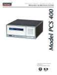
Figure 1.1: The Optimus System
As illustrated in figure 1.1, the OSP is the master, providing a standard interface
through which the system is accessed. ESP pressure scanners are placed within or
near the item under test and their measurement ports are attached to the pressure
taps on the item under test using flexible tubing. Up to eight (8) ESP pressure
scanners or MicroScanners in any combination are connected via cable to the
miniature Scanner Digitizer Interface, mSDI, which can be placed within the test
article, within the support structure, or at any convenient location up to a maximum
of 150 feet away from the scanners. An mSDI is connected to an Optimus Fiber optic
Interface, OFIU, located within the OSP, via a single multi-mode fiber optic cable.
Power is supplied directly to the mSDI from a Remote Power Supply, RPS, using a
separate cable. The OSP can contain up to four (4) OFIUs and thus be attached to up
to four (4) mSDIs, requiring up to four (4) RPS.
Optimus User Manual: Introduction, Page 11
Introduction: Continued
Expansion chassis can be added to the system, each capable of accommodating up to
four (4) input units; pressure calibrators and pressure standards. These expansion
chassis are available in two types: Remote Processors, RP, and Local Slaves, LS. An
RP contains its own power supply and communicates with the OSP via a dedicated
RS-485 cable. Up to three (3) RPs may be added to the system. An LS takes its power
from an RP via cable and so it must be located in close proximity to an RP. An LS
chassis communicates with an RP via a General Purpose Interface Bus, GPIB,
independent of the OSP serial communication link. Up to seven (7) LS racks may be
connected to one RP.
Input units that may be installed in either an RP or LS include: Pressure Calibration
Units, PCU, which provide precise pressure calibration and performance verification
information prior to start of test and Pressure Standard Units, PSU, which are read
only precision pressure standards used to measure tunnel parameters having higher
accuracy and precision requirements than the ESP scanners provide. It must be
noted that pressure-standard, PSU, and pressure-generating, PCU, units each require
two (2) slots and that unused slots must be occupied by dedicated Blanking Panels.
It is common to use RP and LS racks to locate PCUs and PSUs close to ESP pressure
scanners in order to reduce calibration time and insure utmost accuracy. Both types
of units contain secondary pressure standards that can be read periodically, and
PCUs are capable of generating precision pneumatic pressures in order to calibrate
ESP pressure scanners.
Individuals familiar with the legacy 8400 System may note common features and
structural similarities with the Optimus. Optimus offers a convenient upgrade path
for facilities having an existing 8400 System, by utilizing a common command set and
re-use of 8400 components such as: 8432/8433 Pressure Calibrators, 8438/8439
Pressure Standard Units, 8491 Remote Power Supplies, 8404 Remote Processors, and
ESP pressure scanners. 8400 System components that are retained for use with an
Optimus system are eligible for Upgrades and Service Life Extension Plans to assure
maximum performance.
Optimus User Manual: Introduction, Page 12
Introduction: Continued
System Component Overview
The Optimus Data System provides accurate, high speed pressure data acquisition
from ESP and MicroScanner pressure scanners for windtunnel test and
measurement applications. The system is appropriate for use in boundary layer,
low speed, transonic, supersonic, and hypersonic windtunnels with low and high
channel count requirements. An Ethernet interface to the host computer offers
either: Engineering Unit, EU, data, or Binary, RAW, data for users preferring to
perform EU conversion within their own application. Optimus supports the latest
MicroScanner and the updated Gen-2 ESP pressure scanners as well as many of
the legacy ESP scanners manufactured by Pressure Systems Inc. – Now the
Aerodynamic Research Group within Measurement Specialties Inc.
The Optimus System Processor
The OSP is the central data acquisition and control unit of the Optimus Data
System. Configured for 19 inch rack or bench top installation, the OSP can
support up to 32 - ESP pressure scanners for a total of 2048 measurement
channels. An Ethernet interface allows direct host connection, and expansion
beyond 2048 measurement channels.
OFIUs are installed inside the OSP and communicate with the mSDI via a single
optical fiber. A minimum of one OFIU is required for system operation and up to
four (4) OFIUs can be installed within one (1) OSP. The OFIUs can be factory
installed at time of system production, or can be easily installed by the end user.
Figure 1.2: OSP with OFIU’s installed
Optimus User Manual: Introduction, Page 13
Introduction: Continued
The Optimus Fiber optic Interface Unit
The Optimus Fiber optic Interface Unit, OFIU, is installed within the OSP. This
circuit board communicates with the mSDI scanner interface via a single 62.5
micron multimode fiber. The thin flexible optical cable allows placement of the
mSDI within windtunnel models reducing the cabling that crosses the force
balance.
An OFIU interfaces with one (1) mSDI and a minimum of one (1) OFIU is required
for system operation. A maximum of four (4) OFIU slots are available inside an
OSP. The OFIU fiber optic output is fed through the back panel of the OSP via
industry standard ST fiber optic feed-throughs. OFIUs may be installed at time of
order and can also be ordered separately and installed on site as needed.
Figure 1.3: OFIU and mSDI
The miniature Scanner Digitizer Interface
The mSDI is the connection point for the cables leading to the pressure
scanners. The mSDI provides power to the ESP scanners, performs excitation
feedback measurement, and performs analog to digital, A/D, conversion at high
data rates.
The small size and low power dissipation of the mSDI makes it ideal for
mounting inside windtunnel models. The cross sectional area matches the ESP
64HD scanner, allowing the mSDI to be placed in-line with the pressure
scanners for maximum channel density.
Figure 1.4: mSDI with Scanner and OSCB attached and also RPS via power cable.
Optimus User Manual: Introduction, Page 14
Introduction: Continued
Data transport from the mSDI to the OFIU is via fiber optic cable terminated with
industry standard ST connectors. Power is provided by a RPS and in turn is
distributed to the pressure scanners attached to the mSDI. The pressure
scanners are connected to the mSDI with an Optimus Scanner Cable, OSCB,
which can be purchased in lengths ranging between six (6) inches and one
hundred fifty (150) feet. OSCB cables having a length greater than thirty (30) feet
are only supported when using Gen-2 DTC pressure scanners or MicroScanner
pressure scanners. Within that constraint, any combination of pressure scanners
attached with varied length OSCB cables may be connected to mSDI
simultaneously. OSCB cables utilize standard micro D 15 pin connectors to mate
with any vintage of ESP pressure scanners.
The Remote Power Supply
The RPS is configured for 19 inch rack mount installation or bench mount use
and provides precision regulated power to the mSDI which in turn distributes the
power to the connected ESP pressure scanners. The RPS connects to an mSDI
via an 8476 cable which can be purchased in a range of lengths between ten (10)
and three hundred (300) ft. The RPS uses voltage sense feedback, constantly
monitoring and adjusting power delivered to the mSDI in response to varying
conditions. Though multiple RPS are REQUIRED for installations having more
than two (2) mSDI, an optional “Y” cable, OPCY, is available and permits a single
RPS to power two (2) separate mSDI having a maximum separation of six (6) feet.
Facilities having an existing 8400 System with a legacy RPS must upgrade the
RPS for Optimus compatibility.
Figure 1.5: RPS with Y cable and two mSDI.
Optimus User Manual: Introduction, Page 15
Introduction: Continued
Pressure Scanners
ESP Pressure scanners are classified as either miniature or micro scanners. The
scanners are connected to an mSDI through OSCB which can be purchased in a
variety of lengths ranging between 6 inches and 150 feet. Note that OSCB cables
having a length greater than thirty (30) feet are only supported when using Gen2 ESP DTC pressure scanners or MicroScanner pressure scanners.
The pressure scanners interface with the pressure taps on the item under test
via flexible tubing, typically made of polyurethane. The scanners are commonly
mounted in close proximity to the pressure taps within the test article. In some
cases, the MicroScanner can be mated directly to a test component, without need
of flexible tubing, reducing the volume required for the installation.
Optimus also supports legacy ESP scanners, including products which are no
longer manufactured or supported. The performance achievable with these
scanners is comparable with the current product data sheets within limits.
Those limits include the maximum OSCB cable length and data throughput rate
limits for non GEN-2 scanners.
Figure 1.6: A variety of ESP scanners, from 16HD to legacy and MicroScanner
Optimus User Manual: Introduction, Page 16
Introduction: Continued
Expansion Chassis: Remote Processor and Local Slave
The RP and LS are rack mounted interfaces for the PCU and PSU. They provide
complete pneumatic, electrical and communications interface for these input
units. Up to four (4) input units can be mounted within one expansion chassis.
All pneumatic connections are routed through a pneumatic backplane within the
chassis, allowing convenient and automatic pressure connection from the units
input and output ports through to the pressure scanners.
An RP contains its own AC power supply and communicates to the OSP via a
serial RS-485 cable. Up to three RP’s can be connected to one OSP for a total
capacity of 12 PCUs and / or PSUs.
An LS can be connected to an RP, expanding the number of PCUs supported by
the system. An LS receives power from the RP, communicates through the RP,
and must be located in close proximity to the RP.
These chassis may be sited near the OSP, or remotely near the pressure
scanners. Locating the RP and LS chassis closer to the pressure scanners
reduces the length of the pressure calibration and control lines which can
improve calibration speed due to reduced volume within the pneumatics.
Users with existing 8400 Systems considering upgrading to Optimus can use
properly operating RP and LS without modification. Although the 8400
System is being phased out, these chassis were expected to be a part of the
Optimus Data System. It is recommended that the chassis be serviced and
verified to be leak free to ensure that performance goals are achieved.
Figure 1.7: Remote Processor and Local Slave
Optimus User Manual: Introduction, Page 17
Introduction: Continued
Pressure Calibrate Units
A PCU incorporates pneumatic valves, a pressure servo controller, and a high
accuracy pressure standard. Under OSP control, the PCU facilitates the process
of calibrating ESP scanners. PCUs generate pneumatic control signals which
translate the calibration valve within the ESP scanners and also generate
arbitrary precision pressure outputs.
PCUs can only be installed in RPs or LSs and are required for operation of the
system. Owners of legacy 8400 systems may choose to refurbish their
8433/8432 PCUs for use with a new Optimus System.
Pressure Standard Units
A PSU has the same physical dimensions and appearance as a PCU and
incorporates the same high accuracy measurement sensor but lacks the
pressure control hardware. The purpose of the PSU is to measure and
continuously monitor important wind tunnel pressures which may not
associated with the primary item under test. Barometric pressure, tunnel static
pressure and tunnel wall pressure are examples of measurements made with
PSU’s.
PSUs can only be installed in RP or LS. PSUs are an optional component of the
Optimus system and are not required for operation of the system. Owners of
legacy 8400 systems may choose to refurbish their PSUs for use with a new
Optimus System.
Figure 1.8: PCU / PSU
Optimus User Manual: Introduction, Page 18
Theory of Operation:
The Optimus Data System is simple to configure and operate. It is controlled by a
host computer via Ethernet as part of a distributed data acquisition system. After
sending the Optimus System a series of simple human readable setup commands, a
continuous stream of data is returned to the host. The Optimus System's design uses
a highly parallel approach to data acquisition in which data is acquired by separate
input units, each having its own microprocessor. An input unit operates on a unique
data acquisition profile, producing time-tagged data records which are then inserted
into the system data stream. This parallel, concurrent, scanning methodology
provides unprecedented acquisition speed and control capability.
All input unit processors communicate with the OSP via Ethernet or serial data links.
The OSP coordinates and controls each input unit, off-loading many tasks, such as
calibration and data acquisition, allowing them to be performed independently. The
OSP is free to do the other functions for which it is best suited for example: process
coordination and scheduling, Engineering Unit data conversion, and host
communications.
A basic Optimus System configuration will contain:
1) An Optimus System Processor, OSP, having a minimum of one (1)
Optimus Fiber optic Input Unit, OFIU, installed
2) A miniature Scanner Digitizer Interface, mSDI, which routes power,
performs logical control, and digitizes the output of ESP pressure
scanners.
3) An ESP scanner that samples multiple pressure taps on a windtunnel
model.
4) A Remote Power Supply, RPS, which supplies power to the mSDI and the
ESP scanners attached to it.
5) A Remote Processor, RP, providing power and pneumatic interface for
Pressure Calibrate Units and / or Pressure Standard Units.
6) A Pressure Calibrate Unit, PCU, for performing calibration and
verification of the ESP Scanner performance.
7) Sufficient Pneumatic Blanking Units, PBUs, which are installed in the
unused slots of the RP, sealing the unused pneumatic interfaces.
8) Interconnection cables for power and communication.
9) A host computer and application software which configures the Optimus
and stores the data returned from it.
Optimus User Manual: Theory of Operation, Page 19
Theory of Operation: Continued
Figure 2.1: Optimus Basic System
System Component Overview
The Optimus System Processor
The OSP incorporates a Freescale MPC8308 32-bit microprocessor and integral
Gb Ethernet switch, supporting an internal distributed Ethernet architecture. All
input unit and expansion chassis communication is accomplished via this
isolated internal network. The system application runs upon the Linux operating
system which offers long term viability and upgradability of the application and
the opportunity to quickly incorporate advanced features in response to
customer requirements. See Appendix Z for FOSS licensing information.
Though the OSP application runs under the Linux kernel, the OFIUs are built
upon Real Time Operating System, RTOS, applications that ensure deterministic
data acquisition. RPs, LSs, and PCUs utilize state machines; embedded
applications that perform singular tasks. The analog ESP scanner data
acquisition is performed by the OFIUs. The OSP application: accepts commands
from the data acquisition host computer, configures the internal system
components, coordinates the operation of the system components, time-tags the
data packets being acquired by the OFIUs, performs floating point conversion of
the Engineering Unit data, and manages data transmission.
Optimus User Manual: Theory of Operation, Page 20
Theory of Operation: Continued
Figure 2.2: Communication path Block Diagram
The OFIU is a plug-in module located within the Optimus System Processor. Up
to four (4) OFIUs may be installed within an OSP. An OFIU communicates via a
single fiber optic cable with a miniature Scanner Digitizer Interface, the mSDI.
The OFIU and mSDI work together to address, and digitize the output of, the
pressure ports of ESP scanners connected to the mSDI. The fiber optic cable
connecting the OSP and OFIU and the mSDI can be up to one thousand (1000)
meters in length. The mSDI requires that a Remote Power Supply, RPS, be
located within one hundred (100) meters.
An OFIU and mSDI can accommodate up to eight (8) ESP pressure scanners
having a maximum aggregate channel count of 512 channels. The OFIU and
mSDI scan and digitize all pressure ports of the attached scanners using one (1)
of four (4) predetermined channel scan lists or Tables. The host application can
switch quickly from one Table to another without being required to re-transmit
and execute individual configuration commands.
OFIU and mSDIs are fully backwards compatible, supporting both conventional
and DTC ESP scanners. ESP miniature scanners are typically located within, on,
or near the test model and are connected to the mSDI via cables designated
OSCB. Conventional ESP scanners provide a pressure output voltage per
channel and require a full multipoint calibration in order to output engineering
unit data. The need for a full multipoint calibration when using Conventional
ESP scanners explicitly requires an RP and Pressure Calibrate Units, PCUs.
Conventional ESP scanner pressure coefficients are not stored within the
Optimus and must be either: saved externally by the host application or
recreated every time the scanners are used. DTC ESP scanners not only provide
Optimus User Manual: Theory of Operation, Page 21
Theory of Operation: Continued
pressure output but also temperature and excitation voltage of the scanner. This
data is utilized in conjunction with factory determined, permanent, pressure
conversion coefficients for each pressure port, stored on an EEPROM within the
DTC ESP scanner itself. This feature allows DTC ESP scanners to operate
accurately over large temperature ranges without having to regularly perform full
pneumatic pressure calibrations. The OFIU uploads the DTC coefficients to the
OSP on start up, and is then ready to acquire data and convert it to Engineering
Units.
Figure 2.3: mSDI Block Diagram
The major blocks of the mSDI are: Analog to Digital Converter (ADC), Address
and Control Logic, eight (8) channel analog multiplexer, instrumentation
Amplifier, and Fiber Optic communications channel to the OFIU. The ADC’s
digital output is a 16-bit unsigned binary number with values in the range 065535 (0000-FFFF Hex). Zero volts is digitized to an “offset” value in the middle
of this range, 32768 or 0x8000, in order to obtain bipolar voltage measurements.
Optimus User Manual: Theory of Operation, Page 22
Theory of Operation: Continued
When raw data are output to the host, the OSP converts them to signed short
integers, in the range -32768 to +32767, or equivalent voltages approximating
-5.0000 to +5.0000 volts. In addition, averaged raw data, 24-bit unsigned integer
partial sums not yet divided by the number of samples per average, may also be
output.
OFIU and mSDI are interconnected via a high-speed fiber-optic link that only
transmits digital data. A single mSDI can connect to and scan up to 8 DTC or
Conventional ESP scanners. A separate power cable connected between the
Remote Power Supply, RPS, and mSDI powers the attached scanners and the
mSDI itself. An optional “Y” cable, OFCY, permits a single RPS to supply power
for two (2) mSDI.
Expansion Chassis: Remote Processor, RP, and Local Slave, LS.
An Optimus System Processor supports 12 pressure ranges, but has no rack or
pneumatic interfaces in which to install PCUs or PSUs. Remote Processors and
Local Slaves provide the racks for installing these units and have a pneumatic
manifold for routing the necessary calibration, reference, and control lines.
The Optimus System can be expanded using RPs, to a maximum of three (3), and
or LSs, to a maximum of seven (7) per RP, and each of these chassis contains
eight (8) slots for PCUs or PSUs. These expansion chassis are linked to the OSP
via a serial interface, providing control and data communication for a maximum
of twelve (12) input units.
Optimus User Manual: Theory of Operation, Page 23
Theory of Operation: Continued
Pressure Calibrate Unit, PCU, and Pressure Standard Unit, PSU.
PCUs and PSUs occupy two (2) slots within an RP or LS chassis. The PCU is a
general purpose, digitally controlled, pneumatic calibration source and pressure
generator. It generates pressure by modulating a pressure supply against a
pressure sink; the vacuum inputs or vent ports. The supply, sink, output, and
reference pressures enter and exit the PCU via a pneumatic manifold
incorporated into the RP or LS chassis. A PSU is a PCU without the ability to
Figure 2.4 PCU and PSU Block Diagram
generate pressure but still incorporating a high accuracy pressure standard
transducer. PCUs and PSUs are available in a variety of pressure ranges. Each
PCU is “keyed” to output its generated pressure through one port, assigned by
the pressure range. Two PCUs keyed for the same port cannot be placed in the
same chassis. In installations where two or more PCUs of the same range are
required, it is possible to either add a separate expansion chassis or to modify
the output port assigned to one of the instruments to prevent conflict.
Measurement Specialties has produced a variety of PCUs and PSUs,
including low pressure absolute, differential with high line-pressure
capability, and temperature compensated resonant quartz versions. All of
these legacy instruments are compatible with Optimus and are eligible for
service life extension programs.
Pressure Blanking Unit, PBU
All of the slots within an Expansion chassis must be sealed for the system to
operate correctly. Slots that are unoccupied by PCUs or PSUs must be filled
using PBUs. These units are passive, taking no part in data acquisition.
Optimus User Manual: Theory of Operation, Page 24
Theory of Operation: Continued
The Optimus Boot Process
The Optimus, in addition to being a chassis containing necessary components, is
an embedded application residing within non-volatile storage on the system
processor board.
Simultaneous to and separate from the Linux boot process, the OFIUs boot up,
determine that an mSDI is attached to their fiber optic interfaces, and also
whether any ESP DTC scanners are connected to the mSDI. If the OFIU
determines that ESP DTC scanners are connected to the mSDI, it will
immediately begin extracting the temperature and pressure correction
coefficients from within the DTC Scanner internal memory. Once the OFIU has
completed this process it will wait for a TCP/IP connection from the Optimus
application, resident on the OSP main circuit board.
After the Linux kernel has completed the boot process, the front panel LED
display is configured; displaying network link status and rate, and whether the
Optimus application is operating. Optimus searches the internal, to the OSP,
network, establishes a TCP/IP connection to each of the installed OFIUs, and
also to the Remote Processor communication server. The status of the OFIUs and
the RP communication link are indicated on the front panel LED display.
Optimus is now prepared for a TCP/IP connection from a host PC, which must
configure the Optimus for data acquisition. Optimus cannot begin data
acquisition autonomously, nor will it automatically discover PCUs or PSUs.
The Data Acquisition Process
Before describing the configuration of the system it is necessary to generally
describe the manner in which data is acquired and its treatment or manipulation
while being assembled for transmission to the controlling host application. This
short section presents terms and concepts that, while not complete, are
necessary to understand the system configuration.
Optimus is a scanned, multiplexed data system meaning that each of the ports
on the attached ESP scanners, and in turn each of the individual ESP scanners,
is selected by a digital word or Address. An address word list, a Scan List, is
created that defines the order in which each port of every ESP scanner is
sampled.
The Scan List is created and maintained within the OFIUs in response to the
OFIU configuration commands sent by the host application. When the system is
Triggered, commanded to acquire data, the address words stored in the Scan List
are applied, in sequence, to the address input pins of the ESP scanners cable
connector, selecting the analog voltage output of the ESP scanners port. The
voltage output is digitized and the resulting Single Point value is stored in
memory in preparation of being manipulated mathematically. The stored array of
values resulting from a single traversal of the Scan List is referred to as a single
Frame of data.
Optimus User Manual: Theory of Operation, Page 25
Theory of Operation: Continued
Averaging of a number of Frames may also be performed in order to increase
resolution and reduce random noise. The resulting Frame of data, whether it is
an average derived from several traversals of the Scan List or a single data point,
is referred to as a Measurement Set; an array of data containing a single value
for each port of every ESP scanner that is physically attached to the mSDI.
When the Optimus is Triggered, Frames are acquired and assembled into
Measurement Sets, and a specified number of Measurement Sets are transmitted
to the host application. The number of Measurement Sets transmitted can be
continuous, started and stopped by an explicit command, or bounded, begun by
an explicit command and ceasing after a specific number of Measurement Sets
has been acquired and transmitted. The internal operation of Optimus favors
streaming data continuously and host applications must utilize this method in
order to optimize throughput.
Figure 2.5: Scan List, Muxs, ESP scanner, ADC, and Data Output array.
Optimus User Manual: Theory of Operation, Page 26
Theory of Operation: Continued
The Optimus Configuration Process
A basic Fiber Input Unit, OFIU, Configuration
The Optimus Data System must be explicitly configured for the desired data
acquisition profile before it will begin acquiring and transmitting data. In
addition, the user application must continuously maintain the TCP/IP socket
connection to Optimus until such time as it is no longer required to acquire and
transmit data. Though there are a wide range of functional parameters available,
which may be manipulated to control the acquisition process in fine detail, a
reasonable acquisition profile can be quickly established using a subset of the
commands listed in later sections of this manual.
Note: A data acquisition profile, a Table, must be explicitly defined, immediately
after a TCP/IP connection is established. Default values for functional parameters
are the exception and profiles are not stored across re-boots or between TCP/IP
connections.
Configuration of Optimus for a data acquisition profile, a Table, is accomplished
by defining the following.
1) The number of ESP scanners connected to the system.
2) The number of Ports contained within each ESP scanner.
3) The OFIU and mSDI to which each ESP scanner is connected.
4) The channel, connector, on the mSDI to which each ESP scanner is
connected.
5) The number of samples, Frames, which will be averaged to derive
each Measurement Set.
6) The Rate at which the Frames will be acquired.
7) The Rate at which the Measurement Sets will be transmitted by the
System to the host application.
8) The number of Measurement Sets that will be transmitted.
9) The number of total ESP scanner ports that will be included in the
Measurement Sets transmitted to the host application.
The parameters, above, are defined by three discrete commands, which must be
sent to an OFIU to which ESP scanners are connected. Following is a description
of the ‘SDx’, Scanner Digitizer, configuration commands. Some details, necessary
for understanding the calibration of ESP scanners and expansion to encompass
multiple OFIUs, will be lightly touched upon and omitted where necessary to
avoid over complication of the concepts presented.
Optimus User Manual: Theory of Operation, Page 27
Theory of Operation: Continued
Definitions:
LRN – Logical Range Number; an arbitrary number, value ranged from
one (1) to twelve (12), used to associate an ESP scanner with a
PCU, Pressure Calibrate Unit, in support of calibration of the
ESP scanners.
CRS – Cluster, Rack, Slot; A numeric representation of the physical
location of a PCU or OFIU within the Optimus System chassis.
Frame – A collection of data, containing values for the individual ports
of a group of ESP pressure scanners.
Measurement Set – A Data Structure created using one or more
Frames and transmitted to the host computer
connected to the Optimus Data System.
Table – A Data Acquisition profile defining the manner in which a
Measurement Set is collected and returned to the host
computer. A single table can encompass multiple OFIUs.
In the listing of parameters that must be defined, items 1 – 4 are set using the
‘SD1’ command, items 5 – 8 are set using the ‘SD2’ command, and item 9 is set
using the ‘SD3’ command.
By convention, the first command to be issued is the ‘SD1’. This command
applies to an OFIU and its mSDI installed at a specific location within the system
chassis, defined by the CRS, Cluster, Rack, and Slot number. Each ESP scanner,
attached via an OSCB cable to the mSDI, is listed in the body of the ‘SD1’
command indicating: the number of the mSDI connector to which it is attached,
the number of ports on the ESP scanner, and the LRN, Logical Range Number, of
the PCU with which it will be calibrated.
The form of the ‘SD1’ command, from the Programmers Reference chapter of this
User Manual is:
“SD1 CRS (Scnr Nports LRN) (Scnr Nports LRN) …;”
Where:
Scnr – The mSDI connector to which the ESP scanner is connected.
Nports – The number of pressure measurement ports on the ESP
scanner.
Optimus User Manual: Theory of Operation, Page 28
Theory of Operation: Continued
For example, for a system configuration having two (2) ESP DTC 32 port
scanners attached to connectors 1 and 2 of an mSDI, and that mSDI connected
with the first OFIU in an Optimus System Processor, the ‘SD1’ command is:
“SD1 111 (1 32 1) (2 32 1);”
To re-cap; this command specifies that “The ESP scanner attached to connector
number one (1), of the mSDI associated with the OFIU at system chassis location
CRS 111, has 32 pressure ports and is to be calibrated by the PCU identified as
Logical Range LRN one (1). The ESP scanner attached to connector number two
(2), of the mSDI associated with the OFIU at system chassis location CRS 111,
has 32 pressure ports and is to be calibrated by the PCU identified as Logical
Range LRN one (1).”.
The parameters of this ‘SD1’ command explicitly state that there are two ESP
scanners, that they have 32 pressure ports each, and that they are attached to
connectors numbered one (1) and two (2) on the mSDI. It also implies that both
ESP scanners have a full scale pressure range that is, if not identical, certainly
compatible because they are both assigned to use the same Pressure Calibrate
Unit; LRN one (1).
After issuing the ‘SD1’ command, the acquisition profile of this Table is set using
the ‘SD2’ command. The ‘SD2’ command applies to a single OFIU and its mSDI
at a specific location within the system chassis, specified by the CRS, Cluster,
Rack, and Slot number. The ESP scanners are not indicated in this command.
Only the collection parameters for a single Table of this OFIU are set including:
the number of Frames that will be averaged to generate a Measurement Set, the
total number of Measurement Sets to be transmitted, the rate at which
Measurement Sets will be delivered, and the Trigger event that will drive
acquisition of the Measurement Sets.
Figure 2.6: Two ESP scanners connected to mSDI connectors 1 and 2
Optimus User Manual: Theory of Operation, Page 29
Theory of Operation: Continued
The form of the ‘SD2’ command, from the Programmers Reference chapter of this
User Manual is:
“SD2 CRS sTBL (nFR FRd) (nMS MSd) (TRIG SCNm) OCf;”
Where:
sTBL – The number of the Table being defined.
nFR – The number of Frames to be averaged.
FRd – The Amount of time between each Frame, in microseconds.
nMS – The total number of Measurement Sets to be output.
MSd – The interval at which the Measurement Sets will be output.
TRIG – The trigger event that will start the acquisition.
SCNm – The Scan Mode for acquiring data.
OCf – The data Output and Conversion Format.
For example, continuing the configuration described earlier, in order to use Table
one (1) to acquire Measurement Sets continuously at ten (10) Hz, each
Measurement Set being the average of ten (10) Frames, with the Format of the
Measurement Set being an array of IEEE floating point values, the ‘SD2’
command is:
“SD2 111 1 (10 0) (0 100) (FREE PAM) 2;”
To re-cap; this command specifies that “When commanded to start acquiring
data using Table one (1) for the ESP scanners indicated in the ‘SD1’ command of
the OFIU and mSDI at chassis location CRS 111; acquire 10 Frames of data and
calculate the average value for each of the scanner port values, calculate the
Engineering Unit value for each of the port data values in the averaged Frames,
Structure the Measurement Set data as an array of Floating Point values,
Transmit the Measurement Set to the host computer, and repeat the process
every one hundred (100) milliseconds until commanded to stop.”.
The ‘SD2’ command is not dependent on the number of ESP scanners or the
number of ports on those scanners. In this example the Measurement Set will
have 64 values contained within it, one (1) for each of the ports of the ESP
scanners specified in the ‘SD1’ command, and each port value will be the average
of ten (10) samples, Frames, acquired as rapidly as the OFIU can traverse the
Scan List. The Measurement Sets will be transmitted on one hundred (100)
millisecond intervals.
Optimus User Manual: Theory of Operation, Page 30
Theory of Operation: Continued
Once the ‘SD1’ and ‘SD2’ commands have been sent the ‘SD3’ command
completes the configuration of the OFIU. The ‘SD3’ command applies to a single
OFIU and its mSDI at a specific location within the system chassis, specified by
the CRS, Cluster, Rack, and Slot number. ‘SD3’ specifies the order of ESP
scanner port data contained within the Measurement Sets being transmitted by
the Optimus. Though one can direct that the ESP scanners port data be returned
in any order, it is typically returned in an array having the first value being the
first port of the first ESP scanner progressing incrementally through the last port
of the last ESP scanner.
The form of the ‘SD3’ command, from the Programmers Reference chapter of this
User Manual is:
“SD3 CRS sTBL sPort [sPort] ...;”
Where:
sPort – The three (3) digit number indicating the mSDI connector
number and the port number of the scanner to be placed at
this Measurement Set index. The first digit is the connector
number on the mSDI to which the scanner is attached and the
final two digits are the port of the scanner. Ex; 101 is Scanner
1 port 01.
Note: This command permits entry of an implicit range of ESP scanners and their
ports as well as a list of individual ports from an arbitrary group of ESP scanners.
Continuing the earlier example of two ESP scanners attached to the first two
connectors of the mSDI, we specify that data from all of the ports of both ESP
scanners will be placed in the Measurement Set in the order; first port of the first
scanner through the last port of the last scanner. This is accomplished by
separating the two sPort numbers with a hyphen “-“. The ‘SD3’command is:
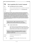
“SD3 111 1 101-232;”
To re-cap; this command specifies that “When creating the measurement Set for
Table number one (1), place the data from the 32 ports of the ESP scanner
attached to mSDI connector number one (1) into array indices 1 through 32 and
place the data from the 32 ports of the ESP scanner attached to mSDI connector
number two (2) into array indices 33 through 64.”.
Once the three commands, ‘SD1’, ‘SD2’, and ‘SD3’, have been executed the
Optimus can be triggered to acquire data using Table number one (1). According
to the Table, the data will be transmitted at ten (10) Hz, every one hundred (100)
milliseconds, in Engineering Units; Volts if the ESP scanners are conventional or
Pounds per Square Inch Differential, PSID, if the ESP scanners are Digital
Temperature Compensated, DTC.
Optimus User Manual: Theory of Operation, Page 31
Theory of Operation: Continued
Optimus can incorporate between one (1) and four (4) OFIUs, each having an
mSDI connected to it. If an OFIU and mSDI pair have ESP scanners attached it
must be configured using an ‘SD1’, ‘SD2’ and ‘SD3’ command sequence. It is
expected that each OFIU and mSDI is configured using the same Table number,
for example Table one (1). In this way all of the connected Input Units will
acquire and output data in response to the same command and trigger.
Optimus User Manual: Theory of Operation, Page 32
Theory of Operation: Continued
Pressure Calibrate Unit, PCU, Configuration
DTC ESP scanners contain non-volatile memory which holds conversion
coefficients for temperature and pressure correction. The non-volatile memory is
read during the OFIU boot process and the coefficient values are stored in
memory for use. DTC ESP scanners are, in general, ready for use as soon as the
warm up interval has passed, as the OSP will use the coefficients to generate
Engineering Unit values from the voltage output by the DTC SEP scanners.
Conventional ESP scanners do not contain non-volatile memory. In order to
output Engineering Unit data for conventional ESP scanners the Optimus
System must calibrate them. This is accomplished by applying a sequence of
pressures to the scanners, recording the voltage output in response to the
applied pressure sequence, and performing a linear regression on the pressure
and voltage data. The resulting coefficients are held in memory for use and can
be adjusted periodically by performing a new calibration. DTC ESP scanners also
benefit from calibration resulting in an accuracy improvement of 40% over
Conventional scanners having the same pressure range.
PCUs are the instruments utilized to set and measure the precision pressure
signals for the calibration of ESP scanners. Like the OFIU they are independently
configurable and operate under direct OSP control. Configuration of PCUs
defines the following.
1) The Operating Mode of the PCU.
2) The Full Scale pressure range of the PCU.
3) The Logical Range Number assignment.
4) The sequence of pressures that will be set when calibrating ESP
scanners.
The parameters, above, are defined by two discrete commands, which must be
sent to all installed PCUs via the OSP. Following is a description of the ‘PCx’,
Pressure Calibrator, configuration commands. Some details necessary for
understanding extended functions and features of PCU operation will be lightly
touched on and omitted where necessary to avoid over complication of the
concepts presented.
Definitions:
LRN – Logical Range Number; an arbitrary number, value ranged from
one (1) to twelve (12), used to associate an ESP scanner with a
PCU, Pressure Calibrate Unit, in support of calibration of the
ESP scanners.
CRS – Cluster, Rack, Slot; A numeric representation of the physical
location of a PCU or OFIU within the Optimus System chassis.
Absolute pressure – a measurement referenced, or relative, to a hard
vacuum.
Differential pressure – a measurement referenced, or relative, to some
other pressure.
Optimus User Manual: Theory of Operation, Page 33
Theory of Operation: Continued
In the listing of parameters that must be defined, items 1 – 3 are set using the
‘PC1’ command and item 4 is set using the ‘PC2’ command.
By convention, the first command to be issued is the ‘PC1’. This command
applies to a PCU installed at a specific location within a Remote Processor, RP, or
Local Slave, LS, chassis, defined by the CRS, Cluster, Rack, and Slot number.
The PCUs LRN, Pressure operating Mode, pressure Setting Tolerance, and
Maximum settable Pressure are listed in the body of this command.
The form of the ‘PC1’ command, from the Programmers Reference chapter of this
User Manual is:
“PC1 CRS LRN, PrM, STol, MaxP;”
Where:
PrM – The Pressure operating Mode, either Absolute or Differential.
STol – The pressure Setting Tolerance, in Pounds per Square Inch.
MaxP – The Maximum settable Pressure, the maximum settable
pressure in Pounds per Square Inch.
For example, continuing the earlier OFIU and OSP system configuration for the
two ESP scanners on an mSDI, we will state that an RP is connected to the OSP
and that a PCU is installed in the first slot of the RP chassis. The PCU is a
Differential pressure controller with a Full Scale pressure range of 45 psiD. We
will use it to calibrate the two ESP scanners that are connected to the first OFIU
in the OSP. In order to logically link the PCU with the ESP scanners we use the
Logical Range Number used in the OFIU ‘SD1’ command with which we defined
the ESP scanners. The ‘PC1’ command for configuring the PCU in the manner
listed above is:
“PC1 211 1, DIFF, 0.0045, 45;”
To re-cap; this command specifies that “The PCU located at Remote Processor
chassis location CRS 211, is declared as the calibrator used for Logical Range
LRN 1, will generate and measure Differential Pressures, will set requested
pressures to within ±0.0045 psi, and will not set any pressures greater than 45
psiD.
The parameters of this ‘PC1’ command explicitly state that the PCU is located in
the first two slots of the first Remote Processor chassis, that it will be used to
calibrate all ESP scanners assigned to LRN 1, that it will set Differential
pressures and all data returned by this unit will be Differential pressure values,
and it will not act upon any request to set pressure greater than 45 psiD.
Optimus User Manual: Theory of Operation, Page 34
Theory of Operation: Continued
After issuing the ‘PC1’ command, the PCU is ready to operate but the ‘PC2’
command is required before ESP scanners can be calibrated. The ‘PC2’ command
applies to a single PCU and specifies the values for, and sequence of, the
Calibration Pressures that the PCU will generate during calibration of ESP
scanners assigned to the PCUs LRN. The Calibration Pressures are selected
based on the full scale range of the ESP scanners being calibrated and the
maximum pressure must not exceed the full scale range of the ESP scanners.
The Calibration Pressure values, the interval between them, and the order are
selected based on best practice which is described in the body of the ‘PC2’
command section of the Programmers Reference in this User Manual.
The form of the ‘PC2’ command, from the Programmers Reference chapter of this
User Manual is:
“PC2 CRS CalP CalP [CalP [CalP [CalP]]];”
Where:
CalP – A Calibration set Pressure. A minimum of two (2) and a
maximum of five (5) Calibration Pressures may be entered in the
‘PC2’ command.
For example, continuing the earlier OFIU and OSP system configuration for the
two ESP scanners on an mSDI, a PCU has been installed in a Remote Processor
expansion chassis and it has been designated to calibrate all ESP scanners that
are assigned to Logical Range LRN 1. In order to accomplish the calibration a
sequence of pressures must be generated by the PCU while recording the
resulting voltage output by the ESP scanners in response to each of the
pressures. The ‘PC2’ command for configuring the Calibration Pressure sequence
is:
“PC2 211 0.0 11.25 22.5 33.75 45.00;”
To re-cap; this command specifies that “The PCU located at Remote Processor
chassis location CRS 211, will set the listed pressures in the specific order, when
a calibration of ESP scanners is requested.”.
The parameters of this ‘PC2’ command explicitly state that the PCU is located in
the first two slots of the first Remote Processor chassis, and lists the ESP
scanner Calibration Pressure values and the sequence in which they will be set.
Optimus User Manual: Theory of Operation, Page 35
Theory of Operation: Continued
The ESP scanner Calibration Process
After the Optimus has been configured, having received appropriate ‘SD1’, ‘SD2’,
and ‘SD3’ commands for each of the OFIUs and also ‘PC1’ and ‘PC2’ commands
to each PCU, the system is ready to be calibrated; deriving fresh coefficients for
each pressure port of the ESP scanners in preparation for data acquisition.
Both DTC and Conventional ESP scanners are calibrated using PCUs, though the
requirements for each differ slightly. Conventional ESP scanners require a full
calibration using the ‘CA3’ command in order to calculate the necessary pressure
conversion coefficients. DTC ESP scanners contain factory derived calibration
coefficients which compensate their data over both pressure and temperature,
only requiring an offset calibration using the ‘CA2’ command in order to achieve
accuracy equivalent to the Conventional scanners. In this section, the full
calibration process will be described in order to further illustrate the operation of
the Optimus System. Description of the ESP scanner coefficients may be found
in Appendix B.
Calibrations are requested for Logical Ranges, groups of ESP scanners associated
with a single PCU. One calibration command, either a ‘CA2’ or a ‘CA3’, can
operate on multiple Logical Ranges simultaneously. All Tables must be
completely defined, having completed execution of an ‘SD1’, ‘SD2’, ‘SD3’, ‘PC1’,
and ‘PC2’ commands, before a Calibration command will execute.
Definitions:
LRN – Logical Range Number; an arbitrary number, value ranged from
one (1) to twelve (12), used to associate an ESP scanner with a
PCU, Pressure Calibrate Unit, in support of calibration of the
ESP scanners.
The form of the ‘CA3’ command, from the Programmers Reference chapter of this
User Manual is:
“CA3 [LRN] ...;”
Where:
LRN – A list of the Logical Ranges to be calibrated.
Optimus User Manual: Theory of Operation, Page 36
Theory of Operation: Continued
For example, continuing the earlier system configuration, two ESP scanners are
attached to an mSDI and an RP is connected to the OSP with a PCU installed in
the first slot. The PCU is linked to the ESP scanners using Logical Range Number
one (1). The ‘CA3’ command for calibrating the scanners described is:
“CA3 1;”
After issuing the ‘CA3’ command, the system will not respond to commands until
after the requested calibration completes.
During a calibration the system performs a set sequence of operations in order to
acquire the data necessary to derive the coefficients for each scanner port. The
sequence of events necessary for calibration is:
1. Receive the ‘CA3’ command
2. Instruct the PCUs to set the C1 control pressure.
a. This places the ESP scanners into a state that permits the
calibration pressure to be applied to the individual transducers
simultaneously.
3. Do in the order defined by the ‘PC2’ command.
a. Instruct the PCUs to set the next pressure from their ‘PC2’
command.
b. Instruct the PCUs to return the value of the pressure that is set.
c. Instruct the OFIU and mSDI to acquire data from the ESP
scanners associated with the LRN.
d. Repeat until all data points have been recorded.
4. Use the acquired data to derive conversion coefficients and store
them for use.
5. Instruct the PCUs to set the C2 control pressure
a. This places the ESP scanners into a state such that the individual
transducers are physically isolated from one another.
6. Send the ‘CA3’ completion message
After completion of the ‘CA3’ command, the system is ready to acquire and
transmit data to the host. It is also possible to extract the coefficients that were
derived for examination or storage using the ‘OP3’ command. The data used to
derive the coefficients, the pressures set by the PCUs and the voltages output by
the scanner ports, may be retrieved using the ‘OP4’ and ‘OP1’ commands
respectively.
Optimus User Manual: Theory of Operation, Page 37
Theory of Operation: Continued
The Data Acquisition Process
The Optimus requires that its components be configured correctly before it will
acquire data. The requirements are:
1. The OFIUs and mSDIs must be defined correctly
a. The ESP scanners attached must be described and assigned to
LRNs in preparation for calibration.
2. The PCUs must be defined correctly, regardless of whether there are
ESP scanners assigned to their LRNs.
Note: Calibration of the connected ESP scanners is not required in order to acquire
data. Data for un-calibrated Conventional ESP scanners will be output in volts,
scaled according to their full scale pressure range. DTC ESP scanners will have
their factory coefficients present in the system but they will not achieve their
specified accuracy until an offset calibration is performed using the ‘CA2’
command.
Data is typically acquired in response to an ‘AD2’ which acquires and outputs
data according to a Table defined by the ‘SD1’, ‘SD2’, and ‘SD3’ commands. The
data is transmitted in Stream Data packets, which are described in Appendix A.
The form of the ‘AD2’ command, from the Programmers Reference chapter of this
User Manual is:
“AD2 sTBL;”
Where:
sTBL – The number of the Table for which data is being acquired.
Optimus User Manual: Theory of Operation, Page 38
Theory of Operation: Continued
As an example, we will consider the configuration that has been described
throughput this chapter. A single OFIU and mSDI have been configured, having
two (2) DTC ESP scanners connected. A single PCU is present in an RP, which is
linked to the scanners through the LRN specified in the ‘PC1’ and ‘SD1’
commands. A calibration has been performed, meaning that the system data will
be within the defined accuracy specification. Data will be requested for Table one
(1), which is configured to acquire and output averaged data at a ten (10) Hz
rate. Data will continue to be acquired and output at this rate until the system is
explicitly instructed to stop, using the ‘AD0’ command. The ‘AD2’ command for
starting data acquisition is:
“AD2 1;”
The host is required to continue reading the data output by the Optimus. When
the data stream is no longer required the stream is stopped by issuing an ‘AD0’
command.
“AD0;”
Optimus User Manual: Theory of Operation, Page 39
Theory of Operation: Continued
Optimus User Manual: Theory of Operation, Page 40
Installation and Setup
This chapter covers the unpacking, assembly, and installation of the Optimus
System. The Optimus System has many components that can be purchased as an
entire system, or as individual pieces of equipment. Before assembling the System,
use the shipping bill as a reference to ensure all parts have arrived. Measurement
Specialties, Meas, takes no responsibility for equipment damaged during shipping.
If containers appear broken, ripped, or damaged, contact the transportation
carrier. If the equipment is damaged, contact Measurement Specialties and ask for
Customer Service.
WARNING! All system, mains, power should be off during
installation or when removing any components from the
Optimus System! Failure to shut off power prior to installation
may cause physical injury or component failure.
Optimus System
The Optimus System consists of many components that operate together under the
control of the Optimus System Processor, OSP. The user can control the OSP using
the free setup software, which can be installed on a host computer. Optimus is
based on a parallel processing concept in order to achieve its high throughput.
Because it is also modular, the system can be easily expanded from modest, less
than 64 channels, to large, more than 1,000 channels, by simply adding compatible
components.
This chapter presents the information necessary to configure and connect each
piece of equipment. To prevent hardware damage this work must be completed
before applying power to the Optimus System.
The Optimus System consists of five (5) groups of equipment:
System Processor, OSP
Expansion Chassis
Remote Processor, RP
Local Slave, LS
Input Units
Fiber optic Interface Unit, OFIU
Pressure Calibrate Unit, PCU
Pressure Standard Unit, PSU
ESP Scanner Interfaces
Miniature Scanner Digitizer Interface, mSDI
Remote Power Supply, RPS
ESP pressure scanners
DTC
Conventional
Micro
Optimus User Manual: Installation and Setup, Page 41
Installation and Setup: Continued
Descriptions:
System Processor, OSP
The OSP controls all components, Remote Processors, Pressure Calibrate Units,
and Fiber Interface Units, while simultaneously providing an interface to the host
computer.
Figure 3.1: OSP
Optimus User Manual: Installation and Setup, Page 42
Installation and Setup: Continued
Remote Processor, RP, and Local Slave, LS
The RP and LS provide pneumatic and electrical interface for one or more
Pressure Calibrate Units, PCUs. They are typically located near to the ESP
pressure scanners requiring calibration by those PCUs. The RP has an internal
power supply, and connects to the OSP via an RS-485 multi-drop serial
interface. An LS draws its power from and communicates through an RP,
providing slots for installing an additional four (4) PCUs. Up to three (3) RPs can
be simultaneously connected to a single OSP. Each RP can have up to seven (7)
LS attached simultaneously.
Figure 3.2: RP
Optimus User Manual: Installation and Setup, Page 43
Installation and Setup: Continued
Input Units
Input Units provide the data acquisition and control functions for the Optimus
System. Self-contained, having their own microprocessors, each IU to operates
independently to perform their tasks. The following IUs are available for the
Optimus System:
Fiber optic Interface Unit, OFIU
The OFIU is an expansion board, installed within the OSP, which connects to a
miniature Scanner Digitizer Interface, mSDI, via a fiber optic cable connected
to the rear panel of the OSP.
If your OSP was ordered with more than one OFIU they will have already
been installed at the factory. If you have previously purchased an OSP and
have now procured a new OFIU the installation kit will include installation
documentation.
Pressure Calibrate Unit, PCU
A PCU is a general purpose, digitally controlled, pneumatic calibration source
incorporating a precision pressure transducer. The PCU provides the valve
control, reference compensation, and calibration pressures for the ESP
scanners. The following table shows available full-scale PCU ranges, suitable
for calibrating any of Measurement Specialties' pressure scanners.
PCUs occupy two slots within an RP or LS. A single RP or LS can contain up to
four (4) PCUs. The OSP has no pneumatic interfaces and so cannot contain a
PCU. PCUs provide calibration and control pressure to calibrate Conventional
and DTC ESP scanners.
Table 3.1
Optimus User Manual: Installation and Setup, Page 44
Installation and Setup: Continued
Pressure Standard Unit, PSU
A PSU is a single-channel, high-accuracy pressure transducer for measuring
Barometric or reference pressure. Generally a PSU is a PCU with the pressuregenerating circuitry removed. Refer to the PCU range table above for available
full-scale ranges.
PSUs occupy two slots within an RP or LS. A single RP or LS can contain up to
four (4) PSUs. The OSP has no pneumatic interfaces and so cannot contain a
PSU..
ESP Scanner Interfaces
miniature Scanner Digitizer Interface, mSDI
Each mSDI can accommodate up to eight (8) ESP scanners. The mSDI receives
all the channel address information from the OFIU and returns the digital data
to the OFIU via the fiber-optic link. The top-plate of the mSDI incorporates
eight (8) connectors for OSCB cables which connect to ESP scanners. As many
as four (4) mSDIs can be connected to an OSP. Power for the mSDI and the
connected ESP scanners is provided by a Remote Power supply, which can be
installed up to three hundred (300) feet away from the mSDI.
Figure 3.3 mSDI with OSCB Cable and ESP scanner
Optimus User Manual: Installation and Setup, Page 45
Installation and Setup: Continued
Remote Power Supply, RPS
An RPS provides precision supply voltages to mSDI and the attached ESP
scanners. The front panel contains four analog current meters, four separate
circuit breakers, a power switch, and a digital volt meter with a four position
selector switch. The output current of each power supply can be continuously
monitored via the analog meters. The output voltage of any of the four supplies
can be checked with the digital panel meter by selecting the desired output
with the four-position selector switch. Each output is protected by a circuit
breaker. The circuit breakers and their reset buttons are accessible on the
front panel.
System Setup
The Optimus System has a variety of equipment options. It is however, important
to recognize that the system is modular and that the individual modules work
together to perform one task; making pressure measurements using the ESP
scanners and returning the pressure data to a host computer. The installation
described below is for a simplified system, beginning with the physical
interconnections; pneumatic, communication, and electrical. The installation of
the Optimus demonstration software will then be detailed followed by: the
description of the power up sequence, the configuration of the system using the
demonstration software.
WARNING! Power to the Optimus System must be off during installation.
A Basic Configuration:
The following shows a basic wind tunnel configuration. The Control room and
Data center for the tunnel is sited in a room adjacent to the test section of the
wind tunnel. The model for this example will be a 3 x 1 x 1 cuboid having 72
pressure taps. All tubing connecting the model pressure taps to the ESP scanner
measurement ports will be equal length and the distances between the various
components will be assigned arbitrary but reasonable values based on the
experience of the author. The lengths of the various interconnecting cables were
chosen based on the values assigned in the example and not due to any
requirements imposed by the Optimus System.
Optimus User Manual: Installation and Setup, Page 46
Installation and Setup: Continued
Figure 3.4 Plan diagram and side view of an arbitrary wind tunnel structure
The following list of equipment has been assembled relevant to figure 3.4.
Delivered from Measurement Specialties
System Hardware
Qty 1, OSP
Qty 1, OFIU, pre-installed in the OSP at CRS 111.
Qty 1, mSDI
Qty 200 Ft, OFIU to mSDI Fiber Optic cable.
Qty 1, RPS
Qty 30 Ft, RPS to mSDI cable.
Qty 1, RP
Qty 200 Ft, OSP to RP communication cable.
Qty 1, PCU, having a Full Scale Range 1 psid.
Qty 6, Pneumatic Blanking Panels.
Qty 2, DTC ESP scanners, each scanner having 64 pressure ports, each
pressure port having an Outer Diameter of 0.04”, and both scanners
having a full scale range of ± 0.36 psiD.
Qty 2, OSCB cables, 10 Ft length.
Qty 1, Optimus Tool Kit.
Optimus User Manual: Installation and Setup, Page 47
Installation and Setup: Continued
Consumable Supplies
Qty 500 Ft, 0.040” polyurethane tubing
Qty 500 Ft, 0.063” Nylon tubing
Qty 500 Ft, 0.25” polyurethane tubing
Qty 10, 0.063” ‘T’s
Qty 10, 0.063” to 0.040” reducers
Qty 10, 0.125” to 0.063” reducers
The OSP, RP, and RPS, have rack-mount flanges for installation into a standard
19" instrument cabinet. These items are mounted in racks at the locations
indicated using a number of screws equal to the number of panel attachment
pockets.
The OSP’s front panel incorporates indicator LED’s and a covered power switch.
These LED indicators present system status in a readily identifiable manner and
should be kept visible during normal operation. The power, Ethernet, and mSDI
fiber optic cable connectors are located on the rear panel of the OSP. It is
necessary that the rack containing the OSP chassis allow access for these
connectors as well as maintaining a minimum one (1) Rack Unit (1U) clearance
above and below the OSP chassis.
The RP back panel must also be accessible for configuration and maintenance. In
addition, PCU’s retained within the RP will vent gas from the ‘VENT’ ports located
at the rear of the RP during normal operation. A modest amount of noise is
generated in the process and should be expected. The front panel access door for
this rack must allow for the installation and removal of the PCUs. In addition,
the RP chassis of the RP must have a minimum one (1) Rack Unit (1U) of
clearance above and below within the rack.
Only a few simple tools are needed to assemble and install the Optimus System.
Measurement Specialties recommends and / or supplies the tools listed below:
3/32" Hex Driver
5/32" Hex Driver
*Offset Wrench 3/8” and 7/16"
*Offset Wrench 1/2” and 9/16"
Straight Slot Screwdriver
Phillips Head Screwdriver
Tubing Pliers
* Supplied with a Optimus System - OSP
Optimus User Manual: Installation and Setup, Page 48
Installation and Setup: Continued
Line Voltage and Fuse Holder
The OSP contains a universal power supply and can be operated on line voltage
around the world by simply changing the power cord for the local standard plug.
An RP does not contain a universal power supply. An RP must be explicitly
ordered, and will be delivered configured for, 100, 120, or 240 VAC at 50Hz or
60Hz. Before installing the power cord in an RP, check the line voltage setting.
The power line setting is indicated by labels on the RP chassis and on a circuit
card located under the fuse holder. If the line power configuration labels are not
present or are damaged; remove the power cord from the power entry module
and slide the plastic fuse cover toward and over the power cord socket, then look
for the numeric value for the line voltage etched on the circuit card. The circuit
card displays the number 100, 120, or 240. The RP chassis are fused for
12 amps using a “Type 3AG, slow blow” fuse at 120 volt A.C. operation or
8 amps, a “Type 3AG, slow blow” fuse for 240 volt A.C. operation.
Important: One of the RP cooling fans is powered directly by the AC Line. If the RP
chassis must be powered with line voltage other than the original configuration,
that fan must also be changed. Consult Meas for details.
OSP J1 – J3 Connectors
Connector J1 is the Ethernet Host port which is capable of operating at
10 Mb / 100 Mb / 1000 Mb.
Note: Connecting the OSP to a 10 Mb Ethernet device is not advisable as the
system will not be able to achieve maximum data rates. Utilizing a 100 Mb
connection is reasonable for modest systems, not requiring the full throughput
capability. For maximum throughput a 1 Gb Ethernet connection is required.
Connector J2 is for RS-485 Remote Processor communications. The
communications cable must be connected prior to power on.
Connector J3 is the optional trigger input. When the OSP is configured to
respond to a trigger signal, it is applied through this connector.
OSP F/O Connectors
Connectors F/O 1 through F/O 4 are the fiber optic connectors for attaching mSDI
to the four OFIU slots within the OSP chassis.
RP J1 - J8 Connectors
These connectors may not be installed. They provide external valve support
function for the C1 and C2 pneumatic control lines and are not normally
required. If the connector is populated then a cable will be present to interface
with an external valve assembly, PN 84SA. A PCU must be located within the slot
to which this connector is routed. For example, if connector J2 is populated, a
PCU must be installed in the first slot of the RP.
Optimus User Manual: Installation and Setup, Page 49
Installation and Setup: Continued
RP J9 Connector
The J9 connector is labeled “Local IEEE 488”. It is not a standard GPIB interface
and cannot be used to control the chassis or input units directly. It is used to
provide local communication to Local Slaves that may be connected to the RP.
RP J10 Connector
The J10 connector is labeled serial interface RS-485. It is attached to connector
J2 of the OSP using a serial cable and provides control for the RP chassis and
the PCUs within its slots. Up to three (3) RPs can be connected via a single,
daisy-chained, RS-485 cable for system expansion.
RP J12 and J12A Connectors
These connectors are labeled as Remote Power. They are used to attach Local
Slaves to the Optimus System Remote Processor.
RP J13, J14, J15, J16, J17, and J18 Connectors
These connectors are unused by the Optimus System.
Optimus User Manual: Installation and Setup, Page 50
Installation and Setup: Continued
RP Pneumatic Interconnections
Pneumatic interface connections are essential and critical for proper operation of
PCUs and PIUs.
There are four (4) classes of pneumatic interconnection:
Attention: Verify all input connections paying particular attention to the High
Pressure supply inputs. Incorrect pressure connection can permanently damage
the PCUs in the chassis.
Supply:
Source and Sink ports; the vacuum and positive pressure inputs with which the
PCUs create the requested calibration pressures.
500 psig Input
Connects the user’s clean, dry, high-pressure source for PCU ranges greater
than 100 PSI. Input pressure should be set to 515 ±5 psig. Maximum
pressure is 650 psig (49 Bar).
100-125 Input
Connects the user’s supply pressure to the chassis. This pressure source
should be clean and dry. It generates the C1 and C2 control pressures
necessary to control the calibration valves. It also is the source for
generating pressures from the PCUs with ranges 100 psia or less. Maximum
pressure is 125 psig.
Vacuum Input
Supplies the necessary vacuum input. Required when setting subatmospheric pressures and pressures just above atmosphere (less than 5
psid) with the PCU. A partial vacuum pump with a 160-liters-per-minute
flow capacity, such as a Sergeant Welch Scientific Model Number 1402 or
equivalent is recommended.
Aux Vacuum Input
“Aux Vac” is the vacuum input for setting all pressures on the 5 and 10 psia
full scale PCUs. A 1/8 inch port for this input increases the vacuum capacity
required by these low range absolute PCUs.
Optimus User Manual: Installation and Setup, Page 51
Installation and Setup: Continued
The Sources for the Supply inputs, 100-125 psig and 500 psig, must be
maintained according to ISO 1873.1; A2, B2, C4.
Dew Point -40 C minimum
Total Oil (Aerosol, Liquid, and vapour), 5 mg/m3
Maximum number of Particles per m3
1-5 micron: 10
0.5-1 micron: 1,000
0.1-0.5 micron: 100,000
The source pressure must be stable in order to prevent fluctuations that can
cause errors during the calibration process
The Vacuum and Aux Vacuum inputs connect vacuum sources to all PCUs
ranged less than or equal to 100 psig and 100 psia. This allows the PCU to set
sub-atmospheric pressures. A vacuum pump must also be connected for the best
PCU performance calibrating ESP scanners ranged ±10 inches H2O, ±20 inches
H2O, ±1 psi, and ±5 psi. This is true even when the ESP scanner will only be
calibrated positive relative to atmosphere. By convention, the vacuum input is
used by PCU ranges 100 psia and below and the Aux Vacuum supplies the 5 and
10 psia range PCUs only.
The Vacuum input should be supplied from a partial vacuum pump with a
capacity of 160 liters/minute or greater.
The Aux Vacuum input should be supplied from a high capacity pump capable of
maintaining 100 Torr.
Control:
Actuation signals used to drive or motivate mechanical components of the
system; specifically within the ESP scanners.
C1 Output
The 100-125 psig pressure output by each PCU to switch the electronic
pressure scanner’s calibration valve to the calibrate position.
C2 Output
The 100-125 psig pressure output by each PCU to switch the electronic
pressure scanner’s calibration valve to the run position.
Optimus User Manual: Installation and Setup, Page 52
Installation and Setup: Continued
Calibration:
Providing a mechanism for derivation or adjustment of the EU conversion
coefficients for the ESP scanners.
Cal Output one (1) through eight (8)
Each PCU is keyed, configured at manufacturing time, to a specific calibration
output. PCUs can reside in any slot within a Remote Processor and their output
will be routed to the assigned output.
Table 3.2
Note: Placing two PCUs having the same pressure range in a single Remote
Processor will result in incorrect operation, potentially damaging components of
the system. If two PCUs having the same Full Scale pressure range are required for
a given system they may be specially ordered such that their Calibration Output is
routed to an alternate output.
Optimus User Manual: Installation and Setup, Page 53
Installation and Setup: Continued
Reference:
An input for the given PCU, the reference pressure of the ESP scanner
during calibration of that scanner.
Cal Ref Input
The Cal Reference port is unused in Optimus. Do not connect any
pneumatic tubing to the Cal Ref port.
Run Ref one (1) through eight (8)
PCU Pressure Standards utilize the ODD numbered Reference ports,
one (1), three (3), five (5), and seven (7) as the reference pressure
measurement point. Differential units set their requested pressures
relative to the absolute pressure sampled from these ports and
Absolute units can be configured to measure the pressure on this
port for the same purpose.
Note: DO NOT Block the EVEN numbered Reference Ports two (2), four (4), six (6),
and eight (8); They MUST BE left open for proper PCU operation. The EVEN
numbered Reference Ports are used by the PCU pneumatic controller as an
exhaust and inlet during operation.
Tubing length and diameter affect the system’s pneumatic settling time. Greater
tubing length on the Cal 1 - Cal 8 lines results in longer stabilization time for a
re-zero or multipoint calibration.
When adapting the control, calibrate, and reference pressures to miniature
pressure scanners, nylon tubing with retaining springs should be used.
Important: The entire Optimus System should be checked for leaks before
acquiring data. Leaks will degrade system performance.
Front Panel Description:
The Front Panel of the OSP incorporates eight (8) LEDs and one illuminated
power switch. The Indicator LEDs are listed in Table 3.2, below.
Table 3.2
Optimus User Manual: Installation and Setup, Page 54
Installation and Setup: Continued
Interconnection Process:
The following description uses the materials and components documented earlier
in this chapter. The process is written from the perspective of inspection of a
newly arrived system. As such, the narrative is intended to suggest rather than
recommend and generalizes some points that may deserve more consideration.
Some components must be acquired from a source other than Measurement
Specialties, such as a regulated source of filtered compressed gas and a vacuum
pump. The location in which the system will be set up should be appropriate for
the purpose, having sufficient space to effectively work around the large
components of the system.
A counter or table is desirable for placement of system components at a height
that is comfortably accessible.
A computer and Ethernet switch are required for operation of the Optimus as a
data acquisition system. Test and validation software is provided free of charge
allowing the user to verify the operation of the system. The documentation of
that software is separate from this user manual. Operation and configuration of
the free software will be generalized, referencing the functions performed. Details
pertaining to the configuration of those functions necessarily depend on the
current software revision as well as the specific combination of hardware being
tested.
Please contact Measurement Specialties Aerospace Research group directly if
assistance is required.
Optimus User Manual: Installation and Setup, Page 55
Installation and Setup: Continued
Unpacking:
Remove each of the components and place them on a bench top or table in a
manner that is convenient and comfortable to work around the system. Check
each component against the shipping documentation to assure all line items are
present.
No component should be connected to mains power until the end of these
instructions.
Remote Processor and Pneumatics:
Inspect the PCU and Pneumatic Blanking Panels. Examine the o-ring seals on
the pneumatic interface of each component, confirming both that they are
present and that they are undamaged.
Examine the Remote Processor paying attention to the rack slots and rails; the
location where the PCU and Blanking Panels are to be mounted. Slide the PCU
into the left slot, CRS location 211, within the remote Processor rack. Using the
5/32” Hex Driver, smoothly tighten the Locking Rods to no more than 25 in/lbs.
Place the Blanking Panels into the remaining slots one at a time using the 5/32”
Hex Driver to tighten the locking rods to no more than 25 in/lbs.
Connect a regulated 100 psig pressure supply to the pneumatic port labeled
“100-125 psig Input” using 0.25” polyurethane tubing. Connect a vacuum pump
to the pneumatic port labeled “Vacuum” using 0.25” polyurethane tubing.
Locate the 0.125” to 0.063” reducers and remove three (3) from the package. The
“barrel”, the body, of the reducers is 0.25” OD. Place one reducer into each of the
following three (3) ports on the back panel of the Remote Processor: C1, C2, and
Cal 2. The 0.063” bulged tube should be exposed and the 0.125” bulged tube
should be inside the ports. Tighten the ferruled connectors onto the body of the
reducers; verify that the ferrule has properly engaged the body of the reducer.
Optimus User Manual: Installation and Setup, Page 56
Installation and Setup: Continued
Optimus System Processor:
Locate the Fiber Optic interface connectors, labeled F/O 1 through F/O 4, on the
rear panel of the unit. Optimus Fiber Input Units that are ordered with a system
are installed in numerical order, lowest to highest number, corresponding to CRS
locations 111 through 114. In this example, since only one OFIU was ordered
with the OSP, the unit is installed in CRS 111 and is attached to connector F/O 1.
Identify the OFIU to mSDI Fiber Optic cable and attach one end to the OSP
connector F/O 1. The cable contains a single multi-mode fiber having identical
‘ST’ connectors on each end and is not polarized; it may be connected in either
orientation. Connect the remaining end of the fiber cable to the Fiber Optic
connector of the mSDI.
Locate the OSP to RP communication cable and note that it has identical ‘D’ shell
connectors on each end. This cable is not polarized and may be connected in
either orientation. Attach one end to the OSP connector J2 and the other to
Remote Processor connector J10.
Connect an Ethernet cable between the Ethernet Switch and connector J1 of the
OSP.
Remote Power Supply:
Inspect the RPS, examining the indicators, connectors, and buttons. Note that
the unit is powered off and do not connect the mains power. Locate the RPS to
mSDI power cable and inspect both ends. The power cable is not polarized and
may be connected in either orientation. Attach one end to the RPS output and
the other end of the cable to the mSDI. Carefully tighten the connector mounting
screws; do not over tighten.
Miniature Scanner Digitizer Interface and DTC ESP scanners:
Remove the DTC ESP scanners from their protective enclosures, placing them
next to the mSDI on the work bench. Remove the protective covers from the first
two connectors on the mSDI, placing them in a container or protective bag for reuse. Locate the two (2) OSCB cables and remove the protective covers from the
end connectors, again retaining them for re-use.
Attach the OSCB cables between the mSDI and ESP scanners. For this exercise,
the selection of one scanner versus another is irrelevant. Carefully tighten the
connector retaining screws to both the mSDI and the ESP scanners: Ensure that
the connector is tightened evenly and gently. Do not over tighten.
Optimus User Manual: Installation and Setup, Page 57
Installation and Setup: Continued
ESP Scanner Pneumatic connections:
Note: Mark all tubing described in the following paragraph. Use either wire
markers or masking tape and pen. Be clear and concise with your notation. Failure
to document the pneumatic interconnects can cause tubing misconnection which
will result in permanent damage to the ESP scanners.
When testing on a bench, it is convenient to keep pneumatics relatively short.
Cut three (3) individual pieces of 0.063” tubing, each being approximately one (1)
meter in length. Attach one length of tubing to the bulged tubes extending from
each of the following connectors on the rear panel of the Remote Processor: C1,
C2, and Cal 2. Label each of the tubes according to the pneumatic connector to
which they are attached.
Attach a 0.063” ‘T’ fitting to each of the labeled lengths of tubing. Cut six (6)
additional pieces of the 0.063” tubing, each approximately 10 cm in length.
Attach the 10 cm pieces of tubing to the remaining bulged tubes of the 0.063” ‘T’
fittings.
Attach one 0.063” to 0.040” reducer to each of the free 0.063” tubes extending
from the 0.063” ‘T’ fittings. Cut six (6) pieces of the 0.040” tubing, each
approximately 10 cm in length. Attach the 10 cm pieces of tubing to the 0.040”
bulged tubes of reducers.
Noting the labels on each of the pneumatic assemblies, attach the tubing to the
correct ports on the ESP scanners: C1, C2, and Cal. The Run and Cal Ref ports
of the scanners must remain open and unobstructed.
Take the time to verify that the tubing and connections are correctly assigned
and attached.
Computer:
Install the test and validation software on the computer. Attach an Ethernet
cable between the computer and the Ethernet switch. Configure the software and
computer per the software documentation.
Power On:
Plug the mains cords into the AC outlet and turn on the Optimus System
components in the following order.
1) Remote processor
2) Remote Power Supply
3) Optimus System Processor.
Optimus User Manual: Installation and Setup, Page 58
Host Operation and Programming
Programmer's Introduction
Once the Optimus System is installed and power is applied it is ready to operate
under host computer control. This chapter deals only with control by the host
computer, hereafter referred to simply as the host. While reading this chapter, you
should memorize any words shown in “bold”. These words are important
terminology, needed to utilize the Optimus System effectively as a programmer.
Commands are simple ASCII strings that begin with a three (3) character operation
code, followed by simple numeric or word parameters delimited by spaces. In order
to make our discussion of commands more concise, there are several conventions
used.
1. Items like the operation code are capitalized meaning that you should
enter them exactly as shown.
2. Parameters are shown as abbreviations.
a. For example, the commonly used input unit address “Cluster, Rack,
Slot” is abbreviated CRS in a command description.
i. These parameters are place holders, meant to be replaced with
actual values.
b. Optional parameters are enclosed in square brackets.
i. E.g. “[ sPort ]”
c. Repeatable parameters are followed by an ellipsis
i. E.g. “...”
3. Single isolated ASCII characters are referred to directly by their long
names, e.g. COMMA or SEMICOLON, or by their actual keyboard key
label enclosed within angular brackets, e.g. “< , >” for COMMA or
“< ; >” for SEMICOLON.
a. Notice that extra spaces separate the label from the brackets to
make the label more readable. When not isolated, as when they are
part of a longer string, these same characters will not be surrounded
by angular brackets.
4. If an ASCII character is unprintable or has a symbolic label not easily
shown within normal text it is shown using standard ASCII character
set abbreviations enclosed within angular brackets; e.g. “<SP>” for
“SPACE” which is ASCII code 0x20, or “<NUL>” for “NULL” which is
ASCII code 0x00.
a. Such symbols are always capitalized and are not surrounded by
blanks. You are expected to enter only that one character not the
brackets or the letters inside when you see this construct. The
“ENTER” key typically generates a “Carriage-Return” ASCII code
0x0D, and will be indicated as “<CR>”.
The Optimus System Processor, hereafter referred to as the OSP, may be accessed
from any host having an Ethernet card and configured with a compatible TCP/IP
address.
Optimus User Manual: Host Operation and Programming, Page 59
Host Operation and Programming: Continued
Host Commands/Responses
To operate the OSP, the host sends a series of commands to which the OSP
responds with acknowledgments, errors, and data. These commands are simple
ASCII strings, which may have mixed lower or upper case alphabetic characters.
Internally, the OSP firmware converts lower-case alphabetic characters to uppercase however; it is a good habit to ensure that all commands are converted to
upper-case before transmission to the OSP.
Host Command Format
Each command begins with an operation code, consisting of two alphabetic
characters and one numerical character, e.g. AD1 for “Acquire Data by method 1”
or SD1 for “Scanner Digitizer operation code 1”. One or more parameters may
follow the operation code as required. Punctuation is allowed but optional,
presuming that all command elements are separated by at least one SPACE.
Numeric parameters may require specific formats including: signed integers, e.g.
111, -1234, signed fixed-point or exponential values, e.g. 66.6, -1.2345, -3.33E-10,
or a range of integers, e.g. 101-132 with the HYPHEN < - > indicating continuous
range inclusive of the terminals. A range of values, when range entry is permitted,
is treated as a single parameter. There must be no embedded SPACEs on either
side of the connecting < - > character.
Word parameters, parameters starting with an alphabetic character, are permitted
in some commands and those constants will be described in the command
documentation. However, alphabetic constants also have numeric value
equivalents. You may use either the alphabetic constant or its numeric equivalent
in host commands.
Parameters must be separated from each other, and from the operation code, by
one or more white space characters, including: SPACE <SP>, TAB <HT>,
COMMA < , >, left parenthesis < ( >, right parenthesis < ) >, and combinations of
these characters.
White space characters are all ignored by the internal command parser as long as
they are used as separators. They may NOT be embedded within parameters or
operation codes, but may surround them. Leading blanks may precede the
operation code. The COMMA < , > and PARENTHESIS < ( ) > characters, or
multiple SPACEs <SP>, may be useful in making lengthy commands more readable.
For example, the command
“SD1 111 101-104 32 1 105-108 16 2;”
may also be written
“SD1 111 (101-104, 32, 1) (105-108, 16, 2);”
to make repeating parameter groups more easily discernible. Most examples in this
document use the later method, with parenthesis as parameter group separators,
to clearly show group repetition; note that the extra parentheses are optional.
Optimus User Manual: Host Operation and Programming, Page 60
Host Operation and Programming: Continued
Each command must end with an explicit termination character, including:
SEMICOLON < ; >
CARRIAGE-RETURN <CR>
LINE-FEED <LF>
NULL <NUL>
You may pack multiple host commands together in a single string with each
command in the string separated by termination characters. The SEMICOLON is
the most commonly used terminator for this purpose. This group of packed
commands may be transmitted to the OSP in a single operation.
For very long command strings, or large strings containing packed commands, the
host may insert trailing continuation characters including:
BACK-SLASH < \ >
PLUS < + >
and the word “MORE”
The command fragment is then transmitted normally to the OSP. The OSP will
allocate internal buffers large enough the hold a worst case system command. As
each continued fragment is received, it is appended to the previous fragment, while
discarding all continuation characters and replacing them with SPACEs. The OSP
continues this process of assembling a command until a fragment is received which
contains a trailing termination character. The OSP then executes the command and
then de-allocates the buffer. Continued commands are useful when assembling
complex, custom scan lists; as noted in the SD3 command documentation.
Blank lines, ones containing only white-space characters and terminator
characters in any combination, will be ignored by the system. A line that contains
unrecognized characters or character groups will be flagged as an illegal or
unrecognized command. Comments within commands are not permitted.
Whether the host receives a normal, packed, or continued command, it will parsed
to obtain single commands which will be executed in sequence.
OSP Responses
OSP responses to commands, including error responses, are structures designed to
be decoded using Case or Switch statements. Since the Optimus is a Big-endian
system you will be required to convert the structure members to the correct format
for your host PC. Details and recommendations will be offered in Appendix J,
detailing the data conversion algorithms.
Every command response begins with a standard 8-byte header followed by the
structured payload; the header and payload structures are documented in
Appendix B.
Optimus User Manual: Host Operation and Programming, Page 61
Host Operation and Programming: Continued
The first four (4) bytes of every packet emitted from the OSP contain, in order: A
single byte Response Code, a single byte Response Type, and a short integer
Message Length.
The Response Code indicates the command or operation that generated
the packet.
The Response Type indicates the structure of the data embedded within
the packet.
The Message Length is the total length of this packet, including the four
byte header, in bytes.
The data structure will be one of the following as indicated by the Response Type:
1) Confirmation or Error Packet
One Confirmation or Error Packet is sent to the host for every
command received, except for those returning the other types listed.
It indicates that the particular command was successfully executed
or contained an error and was NOT executed. A
Confirmation or Error Packet also follows a stream of data packets,
called measurement sets, marking the logical end of the stream. The
SC2 command may be used to optionally disable these responses
from most commands.
2) Single Value Packet
Single Value Packets contain status words or single values such as
the firmware version of the OSP or its input units.
3) Array Data Packet
Array Data Packets contain two dimensional arrays; data structures
such as scan lists, calibration coefficients, calibration voltages,
calibration pressures, etc.
4) Data Stream Packet
Stream Data Packets contain single dimension arrays, the timestamped measurement sets from input units. These data packets are
created by the Data Acquisition process and configured through one
of three (3) tables; data acquisition profiles maintained within the
OSP. Since each input unit emits its own data at its own
independently configured rate, data packets will typically arrive at
the host as a continuous stream. Measurement sets from very highspeed input units will be interleaved between those from slower
units.
Optimus User Manual: Host Operation and Programming, Page 62
Host Operation and Programming: Continued
Host to OSP Communication Protocol
The factory assigned TCP/IP address is engraved on the identification label, located
on the back panel of the OSP, near the power entry module. The client software
may change the TCP/IP address of the system but must first CONNECT to the OSP
using the currently configured TCP/IP Address on TCP port 8400. The client must
either: change its TCP/IP address to be compatible with the OSPs address or
modify its routing table to permit communication. Of course, after the TCP/IP
address of the system has been changed, the client must document the new system
address or use another method to determine the OSP TCP/IP Address.
In order to facilitate system discovery, the Optimus System Processor can emit a
broadcast system status packet which contains the OSPs TCP/IP address and
other useful information; for example whether it is currently connected to another
client via TCP. The OSP discovery packets are broadcast on the local network and
are directed to UDP port 7001. Clients can cause the OSP to emit a discovery
packet by broadcasting a discovery request command directed to UDP port 7000 on
the local network. This mechanism allows the host application to quickly discover
and select any Optimus System on the local network without requiring manual
intervention,
An Ethernet host is a client to the OSP server. The client must connect to the OSP
server on TCP port 8400 before commands and responses can be exchanged. The
client shall only disconnect from the OSP server after all data acquisition has been
completed. Only one TCP/IP connection is permitted and attempting to establish a
second connection will be rejected by the OSP. It is important to remember that
should the host disconnect for any reason the system will stop acquiring data and
require a new TCP connection and re-initialization.
Because Ethernet packets are limited to approximately 1500 bytes, the data packet
may be broken into additional packets. They will be reassembled by the TCP/IP
stack of the hosts’ operating system without requiring any intervention by the
application. The point to the above statement is that, when a TCP/IP connection is
established the operating system allocates a relatively small amount of buffer space
for the receive buffer of the connection. If the receive buffer is filled with responses
from the OSP, the hosts’ operating system will instruct the OSP to hold off sending
any more packets until more buffer space is available. Under normal
circumstances, the host application, the application you are writing to control and
acquire data from the OSP, will read from the receive buffer allowing the operating
system to receive more data. The buffer space allocated by the operating system as
a receive buffer is not to be used as data storage. If the OSP is unable to send data
to the host for an extended period of time, the OSP will assume that the host has
become disabled for some reason and will drop the TCP/IP connection. When the
TCP/IP connection is dropped, read requests for data will fail with a socket closed
error, requiring the establishment of a new TCP/IP connection and re-configuration
of the OSP.
Optimus User Manual: Host Operation and Programming, Page 63
Host Operation and Programming: Continued
Legal Command String Examples
The following are examples of legal commands:
Single commands with word parameters, parentheses and extra blanks are ignored:
SD2 111 1 (1 0 32 0) ITRIG PAM 1;
sd2 111 1 (1 0 32 0) ATRIG PAM 1;
sd2 111 1 (1 0 32 0) 1 2 1;
Various termination characters, parentheses and commas are ignored:
sd1 111 (1, 32, 1);
sd1 111 (1, 32, 1)<NUL>
sd1 111 (1, 32, 1)<CR>
sd1 111 (1, 32, 1)<LF>
sd1 111 (1, 32, 1)<CR><LF>
Packed command string, with 2 commands, single and multiple terminators:
SP0 1; SP2 2;SP0 1;;;; SP2 2<CR><LF>
Long fragmented command with ranges and various continuation characters:
SD1 111 more
(1-4, 16, 1) more
(5-6, 32, 2) more
(7-8, 16, 3);
SD1 111 \
(1-4, 16, 1) \
(5-6, 32, 2) \
(7-8, 16, 3)<CR>
SD1 111+
(1-4, 16, 1)+
(5-6, 32, 2)+
(7-8, 16, 3);
Each command string or fragment of a continued command must be additionally
terminated encapsulated per its particular link driver.
Optimus User Manual: Host Operation and Programming, Page 64
Host Operation and Programming: Continued
Command Overview
Host commands are listed below, first in alphabetical order, then by purpose. Each
command shows the section of this chapter where it is fully defined.
Host Commands - Alphabetical By Operation Code
AD0 - Stop High-Speed (DA) Data Acquisition
AD2 - Acquire and Output Data to Host
CA0 - Stop Pneumatic Pressure Calibration/Generation
CA1 - Generate Arbitrary Output Pressure
CA2 - Start Zero-Only Pneumatic Pressure Calibration
CA3 - Start Full Pneumatic Pressure Calibration
CP1 - Set Pneumatic Pressure Calibration Valve Mode
CP2 - Set Pneumatic Pressure Calibration Stabilization Time
CP3 - Set Post Extra SRQs Per Calibration Point
CV0 - Turn a PCU's Valve(s) On/Off
CV1 - Set Calibration Valve Position For All Scanners
LA1 - Look At a DAU’s 1st-Stage Datum
LA2 - Look At a DAU’s EU Datum
LA3 - Look At a PCU's or PSU’s Various Data
LA4 - Look At any Input Units Type & Firmware Version or Look At the Current
system Date/Time
OD4 - Output Measurement Set Size in Bytes
OD9 - Define Host’s Data Output Format
OP0 - Clear Tables for Pneumatic Pressure Calibration
OP1 - Output a Tables Calibration Voltages
OP2 - Output a Tables Coefficients; Adjustable
OP3 - Output a Tables Coefficients; All
OP4 - Output the Actual Pressures Generated by PCUs
OP5 - Output a Scan List of a Table
OP6 - Output a PCUs or PSUs Internal Coefficients
OP7 - Output a PCUs Internal S100 Table
OP9 - Define Hosts Table Data Format
Optimus User Manual: Host Operation and Programming, Page 65
Host Operation and Programming: Continued
PC1 - Configure a PCU's Pressure-Generation Parameters
PC2 - Define a PCU’s Calibration Pressures
PC3 - Modify a PCU’s Internal Coefficients
PC4 - Change a PCU’s Pressure Units
PC5 - Build a PCU’s Internal S100 Table
PS1 - Configure a PSU or PCU for DAU Operation
PS2 - Define a PCUs or PSUs DAU Setup Parameters
PS3 - Modify a PSUs Internal Coefficients
PS4 - Change a PSUs Pressure Units
SC1 - Set SRQ/EOI Mode for Host Data & Specify IP-Address or RESET
SC2 - Enable/Disable Host Responses from Selected Commands
SC4 - Enable/Disable Host Command Echo & Specify Subnet Mask
SD1 - Configure an OFIUs Scanners
SD2 - Define an OFIUs Setup Parameters
SD3 - Define an OFIUs Scan List
SD4 - Manually enter an OFIUs EU Conversion Coefficients
SD5 - Load or Store OFIU DTC-Scanners EEPROM Coefficients or Force an
OFIU to treat DTC ESP Scanners as Conventional ESP Scanners or Turn
OFIU Temperature Sets Off, On, or Periodic
SP0 - Clear/Reformat Default Memory
SP1 - Copy Initialize Commands To/From Default Memory
SP2 - Enable/Disable AUTO-Initialize On Start-Up
SP3 – Execute a system configurations’ Initialization Commands
SP5 - Display/Set Date-Time
Optimus User Manual: Host Operation and Programming, Page 66
Host Operation and Programming: Continued
Host Commands - By Purpose
INPUT UNIT INITIALIZATION COMMANDS
SD1 - Configure an OFIUs Scanners
SD2 - Define an OFIUs Setup Parameters
SD3 - Define an OFIUs Scan List
SD4 – Manually enter an OFIUs EU Conversion Coefficients
SD5 – Load or Store OFIU DTC-Scanners EEPROM Coefficients or Force an
OFIU to treat DTC ESP Scanners as Conventional ESP Scanners or
Turn OFIU Temperature Sets Off, On, or Periodic
PC1 - Configure a PCU's Pressure-Generation Parameters
PC2 - Define a PCU’s Calibration Pressures
PC3 - Modify a PCU’s Internal Coefficients
PC4 - Change a PCU’s Pressure Units
PC5 - Build a PCU’s Internal S100 Table
PS1 - Configure a PSU or PCU for DAU Operation
PS2 - Define a PCUs or PSUs DAU Setup Parameters
PS3 - Modify a PSUs Internal Coefficients
PS4 - Change a PSUs Pressure Units
PNEUMATIC PRESSURE CALIBRATION OPTION COMMANDS
CP1 - Set Pneumatic Pressure Calibration Valve Mode
CP2 – Set Pneumatic Pressure Calibration Stabilization Time
CP3 – Set Post Extra SRQs Per Calibration Point
PNEUMATIC PRESSURE CALIBRATION CONTROL COMMANDS
CA0 - Stop Pneumatic Pressure Calibration/Generation
CA1 - Generate Arbitrary Output Pressure
CA2 - Start Zero-Only Pneumatic Pressure Calibration
CA3 - Start Full Pneumatic Pressure Calibration
Optimus User Manual: Host Operation and Programming, Page 67
Host Operation and Programming: Continued
OUTPUT PNEUMATIC PRESSURE CALIBRATION DATA
OP0 - Clear Tables for Pneumatic Pressure Calibration
OP1 - Output a Tables Calibration Voltages
OP2 - Output a Tables Coefficients: Adjustable
OP3 - Output a Tables Coefficients: All
OP4 - Output the Actual Pressures Generated by PCUs
OP5 - Output a Scan List of a Table
OP6 - Output a PCUs or PSUs Internal Coefficients
OP7 - Output a PCUs Internal S100 Table
OP9 - Define Hosts Table Data Format
HIGH-SPEED DATA ACQUISITION (DA) CONTROL COMMANDS
AD0 - Stop High-Speed (DA) Data Acquisition
AD2 - Acquire and Output Data to Host
CLEAR/OUTPUT STORED DATA COMMANDS
OD4 - Output Measurement Set Size in Bytes
OD9 - Define Host’s Data Output Format
LIVE-ACTION (LOOK-AT) DATA ACQUISITION COMMANDS
LA1 - Look At a DAU’s 1st-Stage Datum
LA2 - Look At a DAU’s EU Datum
LA3 - Look At a PCU's or PSU’s Various Data
LA4 - Look At any Input Unit’s Type & Firmware Version or Look At Current
Date/Time
VALVE CONTROL COMMANDS
CV0 - Turn a PCU's Valve(s) On/Off
CV1 - Set Calibration Valve Position For All Scanners
SYSTEM COMMUNICATION (HOST PROTOCOL) COMMANDS
SC1 - Set SRQ/EOI Mode for Host Data & Specify IP-Address or RESET
SC2 - Enable/Disable Host Responses from Selected Commands
SC4 - Enable/Disable Host Command Echo & Specify Subnet Mask
Optimus User Manual: Host Operation and Programming, Page 68
Host Operation and Programming: Continued
SYSTEM PROCESSOR CONTROL COMMANDS
SP0 - Clear/Reformat Default Memory
SP1 - Copy Initialize Commands To/From Default Memory
SP2 - Enable/Disable AUTO-Initialize On Start-Up
SP3 – Execute a system configurations’ Initialization Commands
SP5 - Display/Set Date-Time
Optimus User Manual: Host Operation and Programming, Page 69
Host Operation and Programming: Continued
System Start-Up & AUTO-Initialize
Before starting your Optimus System, Chapter 3 should be read carefully, and all
electrical & pneumatic connections made for your configuration. Lift the cover of
and push the power switch on the front panel. The OSP firmware immediately
executes its Initialization routine. After a few seconds, it is ready to serve you, via
the host computer.
Important: If any Remote Processors, RPs, are connected to the Optimus System
they must be powered on before applying power to the Optimus System Processor,
OSP.
If the AUTO-Initialize feature is Set, the OSP reads stored Initialization commands
and parameters from its Default Storage, 32 Mb of Flash, and moves them into
Application Memory where they will be held through the entire operating session,
meaning until power is removed or the OSP is Reset.
Application Memory is the working memory that holds most of the command
parameters entered during operation and provides default values for all commands
if any were loaded there from Default Storage. Then, all Initialization commands are
optionally executed by the AUTO-Initialize function. Any commands meant for
input units are transmitted to those units. If AUTO-Initialize is successful and
completed, no new initialization commands need be sent from the host computer
each time the system is started. The host command SP2, “Enable/Disable AUTO
Initialize On Start-Up”, controls the Auto-Initialize function. If no commands have
yet been placed into Default Storage for your particular configuration, you will need
to enter these commands when you configure your system.
When powered and warmed up at least for one hour, the OSP and all its input units
are ready to operate accurately. You can, of course, operate the system earlier
when absolute accuracy is not your immediate concern.
Full understanding of input unit Initialize commands requires knowledge of the
Data Acquisition processes within the OSP. Please read the Data Acquisition
Review in Chapter 3 if you have not already done so.
Optimus User Manual: Host Operation and Programming, Page 70
Host Operation and Programming: Continued
Input Unit Initialization Commands
The entire OSP and input unit Initialization commands may be stored in Default
Storage so that, if you have enabled the AUTO-Initialize function, they can be
copied into Application Memory and optionally transmitted to the appropriate input
units. The initialization parameters have to be entered by the host application.
Later the initialization parameters may require modification when your test
configuration changes, for example when input units are moved to different slots or
chassis.
Initialize OFIUs
Definitions:
LRN = Logical Range Number; an arbitrary number, value ranged from
one (1) to twelve (12), used to associate an ESP scanner with a
PCU, Pressure Calibrate Unit, in support of calibration of the
ESP scanners.
CRS = Cluster, Rack, Slot; A numeric representation of the physical
location of a PCU or OFIU within the Optimus System chassis.
Frame = A collection of data, containing values for the individual ports
of a group of ESP pressure scanners.
Measurement Set = A Data Structure created using one or more
Frames and transmitted to the host computer
connected to the Optimus Data System.
Table = A Data Acquisition profile defining the manner in which a
Measurement Set is collected and returned to the host
computer. A single table can encompass multiple devices.
The SDx commands define parameters that identify all OFIUs in a system and
specify the configuration of all ESP pressure scanners connected to the OFIUs.
The SDx commands also associate groups of similarly ranged ESP pressure
scanners with a Pressure Calibrate Unit, PCU, using a Logical Range Number,
LRN. This number logically links a PCU capable of generating suitable pressures
to calibrate a groups range during a pneumatic pressure calibration.
Conventional ESP scanners must have had a full five (5) point pneumatic
calibration before any EU data can be output. At the end of this process the EU
conversion coefficients are calculated for every Conventional ESP scanner port. It
is understood that performing a full calibrations periodically for Conventional
ESP scanners can be time consuming and so, once a full calibration has been
performed, a shorter re-zero pneumatic calibration process can quickly eliminate
the largest component of error in the Conventional ESP scanners.
Optimus User Manual: Host Operation and Programming, Page 71
Host Operation and Programming: Continued
DTC ESP scanners, being factory calibrated and Digitally Temperature
Compensated, do not require a full five (5) point pneumatic calibration before
operation. Instead a set of compensation coefficients are uploaded for each DTC
ESP scanner port from non-volatile storage inside each DTC ESP scanner. Once
the DTC pressure and temperature coefficients have been read from the DTC ESP
scanners internal non-volatile memory, the system is ready to acquire and
output EU data. The pneumatic calibration process still exists, however it is
simpler, faster, and is performed less frequently, only adjusting the two lowest
order DTC coefficients, Zero Cz and Span Cs, for each scanned port using a short
two (2) point pneumatic calibration. These adjustable DTC coefficients, in
combination with dynamically calculated DTC coefficients, and the permanently
stored DTC coefficients are used to convert raw pressure data into engineering
units.
The Optimus OFIU is capable of acquiring data from both DTC and Conventional
ESP scanners simultaneously. It should be noted that, if a mixture of DTC and
Conventional scanners are to be used, it is best to put all DTC ESP scanners on
one OFIU and mSDI and to put all Conventional ESP scanners on a separate
OFIU and mSDI. It is also recommended that no Logical Ranges Numbers are
shared between the two scanner types. When this separation is maintained,
pneumatic calibration of both ESP scanner types can be performed
independently.
OFIUs running in their normal Full OFIU Mode acquire and output sensor
Pressure data, sensor Temperature data, sensor Excitation data, and Analog to
Digital converter Zero offset data. The sensor Pressure data is referred to as a
Pressure or Press-Set going forward. The sensor Temperature, sensor Excitation,
and A/D converter Zero offset data are referred to generally as compensation or
Comp-Sets, and individually as Temp-Sets and EZ-Sets respectively. Comp-sets
are used internal to the OSP to dynamically compensate the pressure data as it
is converted into EU. The individual Comp-Sets can also be passed to the host
application, which can be useful in some instances for troubleshooting. One
Ez‑Set is generated at the start of a data stream, immediately before the first
Temp-Set. By default, a Temp-Set is acquired for every Press-Set to ensure rapid
response to temperature changes. In practice, once the ESP scanners have
stabilized in their environment, the rate of sensor temperature change will be
moderated by the surrounding insulating material and the ratio of Temp-Sets to
Press-Set can be increased significantly. It is common practice that, at a 10 Hz
Press-Set rate, Temp-Set to Press-Set ratios of 1/150 or larger are sufficient to
maintain the specified accuracy of the system
Optimus User Manual: Host Operation and Programming, Page 72
Host Operation and Programming: Continued
SD1 - Configure an OFIUs Scanners
This command defines all characteristics of ESP scanners connected to an OFIU
and mSDI including: The mSDI connector to which a scanner is attached, The
number of pressure ports in each scanner, and The Logical Range Number to
which a scanner is assigned. For DTC ESP scanners, the SD1 also specifies
whether the Sensitive Mode, a high gain output setting permitting increased
resolution, will be enabled.
When the SD1 command is executed the OFIU interrogates each of the scanners
listed in the command parameters. Conventional ESP scanners will not respond
to that interrogation and the OFIU will return a warning response for those
scanners. The OFIU will continue to operate in the Full FIU mode, meaning that
all detected DTC ESP scanners will operate as expected and any indicated
Conventional ESP scanners will require a pressure calibration before Engineering
Unit data can be calculated. If no DTC ESP scanners are present, or if the
operator does not require DTC operation, the OFIU may be instructed to operate
in Conventional mode only, requiring a full calibration of all connected scanners
whether DTC or Conventional.
Response:
Confirmation / Error Packet
Format:
“SD1 CRS (Scnr Nports LRN) (Scnr Nports LRN) …;”
Where:
CRS = The Cluster, Rack, Slot number; the physical location where the
OFIU is installed within the OSP.
Range: 111 to 114
The isolated groups of three (3) parameters each are repeated as necessary to
define all scanners connected to the OFIU and mSDI. The scanners may be
specified individually, or in contiguous ranges of scanners having the same
number of pressure ports and the same calibrator LRN. The individual
parameters of each group are specified as follows:
Optimus User Manual: Host Operation and Programming, Page 73
Host Operation and Programming: Continued
Scnr = The Scanner number; the connector on the mSDI to which the
scanner is attached. For DTC ESP scanners, a negative number
may be used to indicate that the scanner should be configured
in Sensitive mode. May be specified as a contiguous range by
separating the two terminals of the range with a hyphen; for
example “1-4” indicates the contiguous range of scanners
attached to mSDI connectors one (1) through four (4) inclusive.
Contiguous ranges of scanners must have the same number of pressure ports
and be assigned to the same PCU LRN for calibration.
Range: ± (1 to 8).
Nports = The Number of pressure ports possessed by the scanner.
Value = 16, 32, 48, and 64; Defined by legacy and standard ESP
pressure scanner configurations.
LRN = The Logical Range Number; A numeral associating ESP scanners
and Pressure Calibrate Units, supporting pressure calibration of
the ESP scanners, in addition to PSUs acquiring precision single
pressure values. The PCU and PSU LRN is specified in the PC1
and PS1 commands.
Range: 1 to 12
Since all scanners connected to an OFIU must be defined by this one
command, you may need to use continuation characters to break up a long
SD1 command.
Example 1:
A System is configured with one (1) OFIU and its mSDI Interface, eight (8)
identical 16-port Conventional ESP scanners, and one (1) PCU appropriate for
calibrating those scanners is assigned to LRN 1. The OFIU SD1 command is:
“SD1 111 (1-8, 16, 1);”
Which states; “The OFIU at OSP slot location 111 has scanners attached to
each of its mSDI connectors. Each of the eight scanners has 16 pressure ports
and they will be calibrated by the PCU designated as LRN 1.”.
Optimus User Manual: Host Operation and Programming, Page 74
Host Operation and Programming: Continued
Example 2:
A System is configured with one OFIU and its mSDI Interface, two (2) identical
48-port legacy Conventional ESP scanners which will be calibrated using a
PCU assigned to LRN 1, and four (4) 32-port Conventional ESP scanners which
will be calibrated by a PCU assigned to LRN 2.
“SD1 111 (1-2, 48, 1) (3-6, 32, 2);”
Which states; “The OFIU at OSP slot location 111 has scanners attached to
mSDI connectors 1 through 6. The scanners attached to mSDI connectors 1
and 2 have 48 pressure ports each and will be calibrated by the PCU
designated as LRN 1. The scanners attached to mSDI connectors 3 through 6
have 32 pressure ports each and will be calibrated by the PCU designated as
LRN2.”.
Example 3:
A System is configured with one OFIU and its mSDI Interface, one (1) 64-port
DTC ESP scanner and two (2) 32-port DTC ESP scanners will use their normal
range and be calibrated using a PCU assigned to LRN 1, three (3) 32-port
Conventional ESP scanners will be calibrated by a PCU assigned to LRN 2, and
one (1) 64-port DTC ESP scanner will use its sensitive range and be calibrated
by a PCU assigned to LRN 3.
“SD1 111 (1, 64, 1) (2-3, 32, 1) (4-6, 32, 2) (-7, 64, 3);”
Which states; “The OFIU at OSP slot location 111 has scanners attached to
mSDI connectors 1 through 7. The scanner attached to mSDI connector 1 has
64 pressure ports and the scanners attached to mSDI connectors 2 and 3 have
32 pressure ports. The three scanners attached to mSDI connectors 1 through
3 will be calibrated by the PCU designated as LRN 1. The scanners attached to
mSDI connectors 4 through 6 have 32 pressure ports each and will be
calibrated by the PCU designated as LRN 2. The scanner attached to mSDI
connector 7 has 64 pressure ports, is to be configured in its sensitive mode,
and will be calibrated by the PCU designated as LRN 3.”.
Optimus User Manual: Host Operation and Programming, Page 75
Host Operation and Programming: Continued
Example 4:
A System is configured with two OFIUs and each has an mSDI Interface. On
the mSDI of the OFIU at CRS 111, four (4) 32-port DTC ESP scanner will use
their normal range and be calibrated using a PCU assigned to LRN 1 and four
(4) 64-port DTC ESP scanners will use their normal range and be calibrated
using a PCU assigned to LRN 3. On the mSDI of the OFIU at CRS 112, three
(3) 32-port Conventional ESP scanners will be calibrated by a PCU assigned to
LRN 2, one (1) 64-port DTC ESP scanner will use its sensitive range and be
calibrated by a PCU assigned to LRN 4, and two (2) 64-port DTC ESP scanners
will use their normal range and be calibrated by a PCU assigned to LRN 1.
“SD1 111 (1-4, 32, 1) (5-8, 64, 3);”
“SD1 112 (1-3, 32, 2) (-4, 64, 4) (5-6, 32, 1);”
Which states; “The OFIU at OSP slot location 111 has scanners attached to
mSDI connectors 1 through 8. The scanners attached to mSDI connectors 1
through 4 have 32 pressure ports each and will be calibrated by the PCU
designated as LRN 1. The scanners attached to mSDI connectors 4 through 8
have 64 pressure ports each and will be calibrated by the PCU designated as
LRN 3. The OFIU at OSP slot location 112 has scanners attached to mSDI
connectors 1 through 6. The scanners attached to mSDI connectors 1 through
3 have 32 pressure ports each and will be calibrated by the PCU designated as
LRN 2. The scanner attached to mSDI connector 4 has 64 pressure ports, is to
be configured in its sensitive mode, and will be calibrated by the PCU
designated as LRN 4. The scanners attached to connectors 5 and 6 have 32
pressure ports each and will be calibrated by the PCU designated as LRN 1.”.
Optimus User Manual: Host Operation and Programming, Page 76
Host Operation and Programming: Continued
SD2 - Define an OFIUs Table Parameters
This command defines data acquisition Tables, profiles which set: the Number of
Frame samples averaged to derive a Measurement Set, the Frame Delay interval
between those Frame samples, the Number of Measurement Sets that will be
acquired, the Measurement Set Delay interval between each Measurement Set,
the Scanning Mode in which the scanner channels are sampled, and the Format
in which the data will be transmitted. Up to three (3) independent Tables may be
set for each OFIU. However, only one of the three tables can be actively
controlling data acquisition at any one time.
Response:
Confirmation / Error Packet
Format:
“SD2 CRS sTBL (nFR[-nFRez] FRd) (nMS MSd) (TRIG SCNm) OCf;”
Where:
CRS = The Cluster, Rack, Slot number; the physical location where the
OFIU is installed within the OSP.
Range: 111 to 114.
sTBL = A Data Acquisition profile defining the manner in which a
Measurement Set is collected and returned to the host
computer. A single table can encompass multiple OFIUs.
Range: 1 to 4
The following six parameters, isolated by parenthesis in the template above,
are unique pairs and are not repeated in the manner of the SD1 scanner
definition. The use of parentheses in the Format is only to illustrate the
pairing of these parameters.
Optimus User Manual: Host Operation and Programming, Page 77
Host Operation and Programming: Continued
nFR[-nFRez] = The Number of Frames which dictates the number of
frames averaged to derive a Temp-Set and Press-Set.
The optional nFRez modifier may be included, which applies in the same
manner to OFIU Ez-Sets.
A value of one (1) specifies that no frame averaging will be performed. Larger
values result in that number of frames being summed within the OFIU and
then transmitted to the OSP. The summed frames will be divided by nFR,
and or nFRez, inside the OSP or host, prior to the application of EU
coefficients.
Range: 1 to 127; Nfrez Default Value = 64
FRd = The Frame Delay, interval between the beginning of scanned
frames
A value of zero (0) specifies no delay between. This parameter is ignored if
the value of nFR = one (1).
Range: 0 to 65000 microseconds
nMS = The Number of pressure Measurement Sets to be acquired when
the Optimus is commanded to acquire data. The Measurement
Sets are acquired and emitted to the host at Measurement Set
Delay intervals.
A value of zero (0) specifies that the OFIU will acquire data continuously,
without bounds, when triggered until explicitly commanded to stop
acquiring data.
A non-zero value specifies that number ‘n’ Measurement Sets will be
acquired and output when triggered, after which the system must be
triggered again.
Note: The value for nMS can be overridden by the command which starts the data
acquisition process. See the ADx commands for additional details.
Range: 0 to 65000
MSd = The Measurement Set Delay the interval between pressure
Measurement Sets.
Note: Specifying a value less than or equal to the time required to acquire a
pressure Measurement Set will cause this parameter to be ignored.
Range: 0 to 600000 milliseconds (10 minutes)
Optimus User Manual: Host Operation and Programming, Page 78
Host Operation and Programming: Continued
TRIG = The Trigger Mode specifies the hardware or software event
which will trigger the acquisition of data.
This parameter accepts either the mnemonic or numeric values listed below.
FREE (0) = Free Trigger. Data will be acquired according to the
(nFR[-nFRez] FRd) (nMS MSd) parameters.
Note: The following two values for TRIG require a digital signal edge transition to
be applied to the Trigger In BNC connector located on the back panel of the OSP.
The ADx command must have been executed prior to the trigger input edge for the
trigger to be active.
ITRIG (1) = Trigger the Initial Measurement Set and continue
acquiring data as specified by the (nFR[-nFRez] FRd)
(nMS MSd) parameters.
ATRIG (2) = Trigger Every Measurement Set explicitly using the
(nFR[-nFRez] FRd) parameters to create the
Measurement Sets. MSd is irrelevant. nMS is still valid.
Note: Impact on System Performance
For an OFIU in Full OFIU mode, an Ez-Set will be acquired before the
trigger starts acquisition of the Press-Set and Temp-Set pairs. The Ez-Set
compensates for excitation variations and A/D converter offset errors
taking a relatively large amount of time compared to pressure and
temperature data acquisition. This delay will significantly reduce system
throughput if the application designer chooses to repeatedly poll the
system for single data points. It is recommended, and more efficient, to
configure a stream of data to be delivered at an appropriate data rate
continuously, either using the FREE trigger or one of the two Hardware
trigger options for trigger mode. This avoids a time delay inherent in
repeatedly acquiring an Ez-Set.
Value = FREE (0), ITRIG (1), ATRIG (2)
Optimus User Manual: Host Operation and Programming, Page 79
Host Operation and Programming: Continued
SCNm = The Scan Mode specifies the method by which the mSDIs
multiplexers and A/D converter perform the selection and
digitizing of individual ports of the ESP scanners.
This parameter accepts either the mnemonic or numeric values listed below.
SEQ (0) = Sequential Address Mode addresses and samples the
scanner ports in the order they are declared in the SD3
scan list.
PAM (1) = Parallel Address Mode addresses and samples the scanner
ports in parallel to achieve higher data throughput. The
data is output in the order declared by the SD3 scan list.
See the Timing Diagram for a detailed description of Sequential and Parallel
Address modes.
Value = SEQ (0), PAM (1)
OCf = The Output and Conversion Format for Measurement Sets
specifies which data, the Temperature, Pressure, and Excitation
and Zero set are delivered as well as the format in which they are
delivered. All Optimus Responses contain a four (4) byte header
indicating: the source of the data, which command evoked it, the
format of the data, the structure, and the number of bytes
contained within the data packet.
1 = The Raw Format returns raw Measurement Sets generated by the
OFIU.
The raw Measurement Sets are arrays of two (2), three (3), or four (4)
byte integers, depending on whether one or more frames are averaged.
The data structure is indicated by the Response Type value embedded
within the data packet. Single point data, created if the nFR parameter
of the SD2 command is equal to one (1), are returned as signed short
integers. Averaged data, created if nFR is greater than one (1), is
returned as either a three (3) or four (4) byte integer sum which must
be divided by nFR to derive the average value.
An OFIU, operating in Full OFIU Mode, will deliver a single raw Ez-Set
and then deliver a raw Temp-Set preceding each raw Press-Set
specified by nMS. Each Temp-Sets raw temperature array is scanned
and assembled according to the scan list for the active Table defined in
the SD3 command.
Optimus User Manual: Host Operation and Programming, Page 80
Host Operation and Programming: Continued
The Ez-Set differs from the Temp-Set and Press-Set by having a single
Excitation value for each ESP scanner defined in the SD1 command
and a single Zero Offset value for the A/D converter within the mSDI.
The Excitation data will be present for scanners even if they are not
referenced in the SD3 command.
2 = The Engineering Unit Format returns Pressure Measurement
Sets generated by the OFIU. The EU Measurement Sets are
arrays of 32 bit IEEE 754 floating point values in Big Endian
order. The data structure is indicated by the Response Type value
embedded within the data packet. The values have been
processed and are the result of Frame Averaging specified in the
nFR parameter.
OFIUs operating in Full OFIU Mode do acquire Excitation, Zero offset,
and Temperature sets from DTC ESP scanners but do not transmit
them to the host. The DTC ESP scanner data is fully compensated for
temperature.
The Engineering Units default to PSI if DTC or Conventional ESP
scanners have coefficients resident in memory. Other units can be
specified using the PC4 command. Conventional ESP scanners that
have not been calibrated and DTC ESP scanners which conversion
coefficients have been read into memory will output data in volts.
Coefficients may be created as a result of calibration using the CA2 or
CA3 commands or loaded into memory using the SD4 or SD5
commands.
3 = The Engineering Unit and Compensation Set Format returns
Pressure, Temperature, and the Compensation Measurement
Sets generated by the OFIU. The Measurement Sets are arrays of
32 bit IEEE 754 floating point values in Big Endian order. The
data structure is indicated by the Response Type value embedded
within the data packet. The values have been processed and are
the result of Frame Averaging specified in the nFR parameter.
OFIUs operating in Full OFIU Mode acquire Excitation, Zero offset, and
Temperature sets from DTC ESP scanners. The Excitation and Zero
Offset, Ez-Set, data is transmitted to the host immediately after a data
acquisition command is received, followed by a Temperature, Temp-Set,
data and then the Pressure, Press-Set. The Optimus then continues
acquiring and emitting Press-Set and Temp-Set data according to the
nFR, nMS, and MSd parameters. Temp-Set data is in ºC by default and
the Ez-Set data is in Volts.
Optimus User Manual: Host Operation and Programming, Page 81
Host Operation and Programming: Continued
Example 1:
Configure Table 1 for the OFIU at OSP CRS 111 to acquire Measurement Sets
continuously at 10 Hz, each Measurement Set being the average of 10 Frames,
with the Format of the Measurement Set being an array of IEEE floating point
values. The internal timer will be used to trigger each Measurement set. Only
the Pressure data in Engineering Units are to be transmitted. No
Compensation sets will be returned to the host.
“SD2 111 1 (10 0) (0 100) (FREE PAM) 2;”
When the Data acquisition command is received the OFIU / Optimus will
begin taking data at 100 millisecond intervals with the interval timer inside
the OFIU controlling the data rate. Each data point transmitted by the system
will be a Pressure Measurement Set, the average of 10 frames of pressure data
that has been converted into temperature compensated Engineering Unit
values.
Example 2:
Configure Table 1 for the OFIU at OSP CRS 111 to acquire an unbounded
number of Measurement Sets in response to a digital edge transition applied to
the Trigger Input BNC connector, each Measurement Set being the average of
10 Frames, with the Format of the Measurement Set being an array of IEEE
floating point values. The trigger signal for each Measurement set will be
generated by an external signal generator at an arbitrary rate. An Ez-Set, The
Temp-Sets, and The Press-Sets will be returned to the host in EU format.
“SD2 111 1 (10 0) (0 0) (ATRIG PAM) 3;”
When the Data acquisition command is received the OFIU / Optimus will
begin acquire and transmit an Excitation and Zero Offset, EZ-Set, packet and
then wait for an edge transition on the Trigger Input BNC connector. When a
trigger signal occurs, the OFIU will acquire a Pressure Measurement Set and a
Temperature Measurement Set each being the average of 10 frames of the
scan list. The Pressure Measurement Set has been converted into temperature
compensated Engineering Unit values. The system will then wait for another
digital transition on the Trigger Input BNC.
Optimus User Manual: Host Operation and Programming, Page 82
Host Operation and Programming: Continued
SD3 - Define an OFIUs Scan List
The SD3 command defines the scan list, the order in which the pressure ports of
the Table are addressed and sampled. Measurement Sets, Pressure and
Temperature data, as well as calibration coefficients and the calibration voltage
data are all returned in this Scan List order. The Compensation, Ez-Set, is
scanned in a static order and is unaffected by the scan list.
After transmitting the scan list for each Table, the system must then either
create or retrieve engineering unit coefficients for all pressure ports defined in
the scan list. This can be accomplished by:
1) Execute an SD5 command to retrieve the DTC ESP scanner coefficients
from their embedded non-volatile storage.
2) Execute a CA3 command to perform a full pressure calibration on the
ESP scanners.
3) Execute a sequence of SD4 commands to explicitly write pressure port
coefficients into the coefficient tables.
Option one (1) is only valid for DTC ESP scanners and may be omitted under
some circumstances; see the documentation for the SD5 command. If the DTC
coefficients are not extracted from DTC ESP scanners then they will be treated as
Conventional ESP scanners and will not be temperature compensated. Options
two (2) and three (3) may be used for all scanner types though they are most
applicable to Conventional ESP scanners.
Response:
Confirmation / Error Packet
Format:
“SD3 CRS sTBL sPort [sPort] ...”
Where:
CRS = The Cluster, Rack, Slot number; the physical location where the
OFIU is installed within the OSP.
Range: 111 to 114.
sTBL = A Data Acquisition profile defining the manner in which a
Measurement Set is collected and returned to the host
computer. A single table can encompass multiple OFIUs.
Range: 1 to 4
Optimus User Manual: Host Operation and Programming, Page 83
Host Operation and Programming: Continued
sPort = The three (3) digit number indicating the mSDI connector
number and the port number of the scanner to be placed at
this Measurement Set index. The first digit is the connector
number on the mSDI to which the scanner is attached and the
final two digits are the port of the scanner. Ex; “101” is
Scanner 1 port 01.
The SD3 command permits entry of an implicit range of ESP scanners and
their ports, as well as an arbitrary list of individual ports from a group of
ESP scanners.
Ex: “101-132” is the inclusive range of scanner one (1) port one (01) through
scanner one (1) port thirty-two (32) and “101-832” is the inclusive range of
scanner one (1) port one (01) through scanner eight (8) port thirty-two (32)
implicitly including all channels of the intervening six (6) scanners that may
be defined in the SD1 command.
The sPort parameter is either repeated or configured as one or more
contiguous ranges that include all scanners and pressure ports that are
desired in this scan list. For complicated scan lists, it may be necessary to
use command line continuation methods such as the keyword MORE.
Example 1:
Configure the scan list of Table 1 for the OFIU at OSP CRS 111 to scan and
output the data for eight (8) ESP scanners. The ESP scanners attached to
mSDI connectors 1, 2, and 3 have 16, 32, and 32 ports respectively. The
remaining five (5) ESP scanners, attached to connectors 4 through 8, have 64
ports each.
“SD3 111 1 (101-864);”
Scan all ports of the ESP scanners referenced in the SD1 command for Table 1
connected to the OFIU and mSDI at OSP CRS 111 in the order; first port of the
first scanner through the last port of the last scanner.
Optimus User Manual: Host Operation and Programming, Page 84
Host Operation and Programming: Continued
Example 2:
There are two OFIU in the OSP, and each OFIU has an mSDI attached. The
first OFIU and mSDI are at OSP CRS 111 and have three – 16 port ESP
scanners attached to connectors 1, 2, and 3. The second OFIU and mSDI are
at OSP CRS 112 and have eight - 32 port ESP scanners attached.
Configure the scan lists for Table 1 to scan and output ports 1 through eight
of each of the three ESP scanners attached to OFIU and mSDI at CRS 111,
and also port 32 of each of the eight ESP scanners attached to OFIU and mSDI
at CRS 112.
“SD3 111 1 (101-108) (201-208) (301-308);”
“SD3 112 1 (132) (232) (332) (432) (532) (632) (732) (832);”
Scan the ports of the ESP scanners referenced in the SD1 command for
Table 1 of the OFIU and mSDI at CRS 111 attached to connectors 1, 2, and 3
in order: scanner 1 port 1 through scanner 1 port 8, then scanner 2 port 1
through scanner 2 port 8, and then scanner 3 port 1 through scanner 3
port 8. Simultaneously, scan the ports of the ESP scanners referenced in the
SD1 command for Table 1 of the OFIU and mSDI at CRS 112 attached to
connectors 1 through 8 in the order: scanner 1 port 32, scanner 2 port 32,
scanner 3 port 32, scanner 4 port 32, scanner 5 port 32, scanner 6 port 32,
scanner 7 port 32, and scanner 8 port 32.
Optimus User Manual: Host Operation and Programming, Page 85
Host Operation and Programming: Continued
SD4 – Manually Enter an OFIUs EU Conversion Coefficients
This command manually enters EU data conversion coefficients to an SP, for
each scanner port scanned by each Table. It is normally used only when
coefficients are not obtainable from either the DTC ESP scanner non-volatile
memory or a full pressure calibration. It is also used to load the factory supplied
DTC coefficients to into the non-volatile memory of DTC ESP scanner. This
command will overwrite coefficients in the specified Table. An extensive
discussion of the derivation and use of both DTC and Conventional ESP scanner
coefficients can be fou nd in Appendix B.
Response:
Confirmation / Error Packet
Format:
“SD4 CRS [-]sTBL sPort [ Coef ] ... ;”
Where:
CRS = The Cluster, Rack, Slot number; the physical location where the
OFIU is installed within the OSP.
Range: 111 to 114.
sTBL = A Data Acquisition profile defining the manner in which a
Measurement Set is collected and returned to the host
computer.
The SD4 command writes calibration coefficients into the indicated Tables
coefficient array. There are two types of coefficients handled by this
command, corresponding to the two types of ESP scanners; DTC and
Conventional.
Calibration of a Conventional ESP scanner is performed in-situ, at the time
the ESP scanner is to be used. The coefficients are valid for the current
state of the scanners and must be updated periodically to ensure accurate
measurements. The Conventional calibration process will derive a set of
coefficients for an ‘n-1’ order polynomial equation, with ‘n’ being the number
of calibration pressure points specified for the ESP scanners. These
coefficients may be stored on the host computer and re-loaded during
configuration to reduce the time required before taking data; however, this
process does not guarantee the system performance specification. It is still
necessary to perform an offset calibration using a CA2 command if this
optional procedure is used.
Optimus User Manual: Host Operation and Programming, Page 86
Host Operation and Programming: Continued
Calibration of DTC ESP Scanners is performed at the factory during
production. The DTC calibration process requires application of multiple
pressures across a number of temperatures. After the calibration data is
reduced, the coefficients are stored in the scanners non-volatile memory and
never require modification for the life of the scanner. In addition to being
placed in the DTC scanner non-volatile memory, the coefficients are
delivered on a CD accompanying the scanner. These coefficients are to be
stored as a local record and can be reloaded into the DTC scanner using
this command in conjunction with the SD5 command.
An in-situ pressure calibration of DTC ESP scanners may be performed as
well. The in-situ calibration derives a first order pressure adjustment,
having only an offset and span correction term, that is applied after the DTC
temperature and pressure corrections have been made. These values, the
DTC Adjustable Group coefficients, can also be stored into the DTC scanner
non-volatile memory, although they may require adjustment at intervals.
The sign of the sTBL value selects the type of coefficients which will be
written to the Table coefficient arrays. A negative Table value writes the
factory coefficients for the DTC scanners into the OSP coefficient array and
a positive Table value writes the Conventional scanner coefficients as well as
DTC scanner Adjustable Group coefficients into the OSP coefficient array.
The coefficients are written into temporary memory and will be erased if the
power is cycled or overwritten if a subsequent SD4 command is executed for
that Table and scanner port. If multiple Tables reference the scanner ports
then the coefficients must be written to all Tables individually.
Range: -4 to -1, for DTC coefficients
Range: 1 to 4, for Conventional coefficients and DTC Adjustable
Group coefficients
sPort = The three (3) digit number indicating the mSDI connector
number and the port number of the scanner to which the
coefficients will be applied. The first digit is the connector
number on the mSDI to which the scanner is attached and the
final two digits are the port of the scanner. Ex; “101” is
Scanner 1 port 01.
Value = A single connected Scanner and Port number. The port for
which the coefficients to be transmitted are valid.
Optimus User Manual: Host Operation and Programming, Page 87
Host Operation and Programming: Continued
Coef = For positive Table values, Coef specifies between two (2) and five
(5) EU conversion coefficients entered from lowest to highest
degree. For Negative Table Values Coef specifies a total of twenty
three (23) floating point values in nine (9) coefficient groups. The
Coef values may be written as Fixed Point, Floating Point,
Scientific, Engineering, or Exponential notation.
Value = Between 2 and 5 values, Conventional, or 23 values, DTC, in
Fixed Point, Floating Point, Scientific, Engineering, or
Exponential notation.
Example 1:
After configuring the scan list of Table 1 for the OFIU and mSDI at OSP
CRS = 111, load the pressure coefficients for Conventional scanner one (1)
port one (01) through scanner one (1) port thirty two (32).
The coefficient list for Conventional ESP scanner 1, by port number, is:
“SD4 111 1 101 (0.15968, 1.14263, 0.00080, 0.00011, -0.00000);”
…
“SD4 111 1 132 (0.05109, 1.15475, 0.00035, 0.00013, 0.00001);”
Load the five coefficients, C0 through C4, for scanner one (1) port one (01) into
the Coefficient array for Table 1 of the OFIU and mSDI at OSP CRS 111.
Incrementally load the five coefficients, C0 through C4, for the remaining
thirty one (31) ports of scanner one (1) into the coefficient array for Table 1 of
the OFIU and mSDI at OSP CRS 111.
Optimus User Manual: Host Operation and Programming, Page 88
Host Operation and Programming: Continued
Example 2:
In preparation of re-writing Coefficients to non-volatile memory within a DTC
ESP scanner attached to connector 1 of the OFIU and mSDI at OSP
CRS = 111, write the scanners coefficients to Table 1. The coefficients will be
written to the scanner using the SD5 command.
The coefficient list for DTC ESP scanner 1, by port number, is:
Put each of the nine (9) coefficient groups on a separate command line within
parentheses and using continuation marks for better readability.
“SD4 112 -1 101 +
(
0.00000000
1.00000000) +
( -16.22416055 -72.29816174 -104.93503733 -50.12542169) +
(
12.44525447
8.72096582
(
0.21483914
0.19328543) +
(
0.10589883
0.06644576) +
(
-0.00013973
0.99985718) +
(
-0.00118181
0.00156580) +
(
0.00015803
0.00043320) +
( 694.28893801 985.21905227
11.43406642
8.38368705) +
70.69070065);”
Optimus User Manual: Host Operation and Programming, Page 89
Host Operation and Programming: Continued
SD5 – Perform DTC scanner specific Functions
This command performs three functions specific to DTC ESP scanners and the
manner in which the OFIU acquires the DTC scanner temperature data.
1) Load or Store DTC ESP scanner Coefficients
2) Enable, Disable, or Periodically acquire DTC Temperature Data
3) Enable or Disable DTC ESP scanner function
Load or Store DTC ESP scanner Coefficients
The most common use for the SD5 command is to move the DTC ESP scanner
coefficients between the non-volatile memory within the scanner and the OSP
memory. The SD5 is executed to read the coefficients into OSP memory
immediately after the SD1, SD2, and SD3 commands are executed. This
operation, of necessity, takes a relatively long time however it only needs to be
performed once when the system is power cycled or if scanners are moved on
the mSDI.
There are five (5) operations which can be performed on the non-volatile
memory within DTC ESP scanners.
1) Read all DTC coefficients from the scanner
2) Write All DTC coefficients to the scanner
3) Write the Adjustable coefficients to the scanner
4) Verify all DTC coefficients in the scanner against the coefficients in
the OSP memory.
5) Erase the non-volatile memory in the scanner.
These functions are performed using a positive Table number. Care should be
taken when performing coefficient writes and memory erase operations.
Ensure that there is a backup copy of the coefficients and only initialize one
scanner at a time to avoid unfortunate incidents.
When performing a Verify operation, it is important to realize that the
verification also applies to the Adjustable Coefficients, the offset and span
coefficients modified by the pressure calibration routines CA2 and CA3. To
avoid a false Verify failure, read all of the coefficients from non-volatile and
then perform the Verification. Since the Adjustable coefficients can be written
back to non-volatile memory within the scanner it is reasonable to limit that
write operation to the calibration lab. This would ensure that the scanner
memory contents can be verified against a known copy of the coefficients.
Note: The Erase adjustable coefficients operation writes the default offset and span
correction terms, zero (0) and one (1) respectively, to these memory locations.
Optimus User Manual: Host Operation and Programming, Page 90
Host Operation and Programming: Continued
Enable, Disable, or Change the period of DTC Temperature Data
acquisition
The second most common use for the SD5 command is used to Enable,
Disable, or change the interval of acquisition of a Temperature Data Set during
Pressure Data Acquisition. When an OFIU is configured and DTC ESP
scanners are detected, the default Temperature Data rate is identical to the
specified Pressure Data rate. This ensures that a fresh temperature value is
acquired for each pressure value allowing continuous compensation for
changes in temperature. The Pressure and Temperature data sets are acquired
in the OFIU concurrently, interleaved temperature for a port and then
pressure for the same port. This default rate will not permit full throughput
and is not required to achieve the stated system accuracy.
The ratio of temperature data sets to pressure data sets can safely be reduced,
such that temperature is refreshed once a minute or even longer if the
temperature of the DTC ESP scanner is stabile. Once a ratio of temperature to
pressure data is set it will remain until it is explicitly changed, either through
issuing a new SD5 command or by a power cycle or reset of the Optimus. The
temperature compensation coefficients are updated every time a new
temperature data point is acquired.
In some instances, for example if the highest data rate is desired for short
intervals, it is necessary to turn the continuous or periodic temperature
updates off. In this case, since the data acquisition is at a high rate and the
data stream duration is short, it is presumed that the initial temperature data
point will be sufficient. A single temperature data point is always acquired
upon a data acquisition request immediately after the Excitation and Zero
Offset Compensation set is acquired.
Enable or Disable DTC ESP scanner function
When an OFIU is initialized with the list of scanners using the SD1 command,
it will determine if any or all of the scanners attached to its mSDI are DTC ESP
scanners. If any scanners identified in the SD1 command do not respond as
DTC scanners, the OFIU will issue a warning that it either, has a combination
of DTC and Conventional scanners attached, or that there were no DTC ESP
scanners identified on the mSDI. Some reduction in performance can be
expected when combinations of DTC and Conventional ESP scanners are
present on a single OFIU and mSDI. In such cases where it is critical to
achieve full throughput the DTC and Conventional scanners may be
segregated, connected to separate OFIU and mSDI in the same OSP. The OFIU
and mSDI having the Conventional scanners attached, can turn off the DTC
specific features of that OFIU, simplifying the configuration of the overall
system and reducing the time required for system initialization.
Optimus User Manual: Host Operation and Programming, Page 91
Host Operation and Programming: Continued
In some applications, it may be advantageous to operate the DTC scanners as
Conventional scanners, configuring the OFIU such that it will ignore the
presence of DTC scanners. In these cases, the DTC scanner retains one
feature available through the SD1 command; the ability to engage the
Sensitive Mode of operation with increased resolution. If this feature is
enabled, it is important to account for the increased sensitivity by reducing
the calibration pressures specified within the PC2 command for the LRN
calibrating that scanner.
Response:
Confirmation / Error Packet
Format:
“SD5 CRS sTBL [actx] [x.x];”
Where:
CRS = The Cluster, Rack, Slot number; the physical location where the
OFIU is installed within the OSP.
Range: 111 to 114.
sTBL = A Data Acquisition profile defining the manner in which a
Measurement Set is collected and returned to the host
computer.
The SD5 command reads calibration coefficients into the indicated Tables
coefficient array. This command is only applicable to DTC scanners and the
operation of the OFIU when DTC scanners are connected.
Range: -2, -1, 0 to 4
-2 = Disable the DTC function of the OFIU. All scanners attached are
treated as if they were Conventional ESP scanners. DTC ESP
scanners that are configured for Sensitive mode of operation remain
in sensitive mode until a new SD1 command is issued. After the
DTC function is disabled the SD5 command will return an error
until the system is reset and re-initialized.
The optional parameters [actx] [x.x] are ignored if present and are not
necessary.
-1 = Set the ratio of Temperature data sets to Pressure Data Sets during
data acquisition. The Ratio is defined by the actx parameter as
follows.
Optimus User Manual: Host Operation and Programming, Page 92
Host Operation and Programming: Continued
actx = 0, Turn off Temperature data sets. Only acquire one
Temperature set at the start of data acquisition.
actx ≥ 1, A Temperature data set will be acquired every actx pressure
data sets. Ex, an actx value of 2 indicates that the OFIU must
acquire one (1) Temperature data set for every two (2) Pressure
data sets.
The optional parameter [x.x] is ignored if present and is not necessary.
0 through 4 = The Table for which the Verify, Read, Write, or Erase
coefficients operation will be valid. Zero (0) specifies to
read the DTC coefficients from all connected DTC ESP
scanners, and place them into all three (3) Tables. If the
Table is set to zero (0) and a write to DTC ESP scanner
non-volatile memory is requested, the first table
containing coefficients will be written to the scanners and
ports defined by the SD1 and SD3 commands.
The parameter [actx] indicates the operation to perform as follows:
actx = 1, Verify All of the coefficients in the DTC ESP scanner nonvolatile memory against the coefficients in the Table indicated
by sTBL.
actx = 0, Read All of the coefficients from the DTC ESP scanner nonvolatile memory into the Table indicated by sTBL.
actx = -1, Write the Adjustable Group coefficients for all ports from
the indicated Table into the DTC ESP scanner non-volatile
memory.
When actx = -1, a value of one (1.0) for the optional [x.x] parameter is
used to clear the Adjustable coefficients to their default values of zero
(0) and one (1) for Cz Offset and Cs Span correction respectively.
When actx = -2, Write All of the coefficients for all ports in the
indicated sTBL into the DTC ESP scanner non-volatile.
Optimus User Manual: Host Operation and Programming, Page 93
Host Operation and Programming: Continued
When actx = -3, Erase All completely erase the non-volatile memory
within the scanner or scanners defined in the indicated table. It is
important to clear the Table and re-initialize the system, such that only
the one scanner to be erased are defined in the SD1 and SD3
commands, before erasing non-volatile memory. Failure to include only
one scanner in the scan list will erase all scanners in the scan list. The
most common use is to identify bad data during a erase, write, read,
and verify operation sequence.
The optional [x.x] parameter is not normally used for actx, except to
modify or read the scanner Header, port zero [0.0], or Trailer, scanner
last port + 1, data. Ex: To read the Trailer data on a 32 port DTC ESP
scanner specify port [33.0] with actx = 1.
A CD containing the factory coefficient update files is provided with each DTC
ESP scanner. These files contain OFIU command scripts that can restore the
DTC ESP scanner to its original state. This operation is not performed except
in the case of an accidental erasure of the scanner non-volatile memory.
DTC ESP scanner coefficients apply to both normal and sensitive range. A gain
factor coefficient that applies to all DTC-scanner ports is used with the
standard coefficient set. The gain factor and other data, such as the serial
number and other identifying information, in the header and trailer sections of
the non-volatile memory, addressed as port 0, the Header, and scanner last
port + 1. The header and trailer data are read into the OSP during the
execution of the SD1 command.
Optimus User Manual: Host Operation and Programming, Page 94
Host Operation and Programming: Continued
Example 1:
Disable the OFIU DTC ESP scanner functions so that it handles every scanner
as a Conventional ESP scanner.
Configure the scan list of Table 1 for the OFIU and mSDI at OSP CRS 111 to
scan and output data for two (2) ESP scanners. The ESP scanner attached to
mSDI connector 1 has 16 pressure ports, a full scale pressure range of ± 1
psid, and is a Conventional scanner. The ESP scanner attached to mSDI
connector 2 has 64 pressure ports, a full scale pressure range of ± 5 psid, and
is a DTC ESP scanner. The DTC ESP scanner will be configured for Sensitive
Mode operation before disabling the DTC scanner features.
“SD1 111 (1 16 1) (-2 64 2);”
“SD5 111 -2;”
“SD2 111 1 (1 0) (100 0) (FREE PAM) 2;”
“SD3 111 1 101-116 201-264;”
Since the Conventional ESP scanner and the DTC ESP scanner are treated in
the same manner, a full calibration is required before EU data can be output.
A PC1, PC2, and CA3 command would follow these SDx commands to
complete the required configuration.
In order to re-enable the DTC function, a full System Reset is required.
Example 2
Change the ratio of Temperature data sets to Pressure data sets. This is a
global change, affecting all Tables.
Configure the scan list of Table 1 for the OFIU and mSDI at OSP CRS 111 to
scan and output data for two (2) ESP scanners. The ESP scanner attached to
mSDI connector 1 has 32 pressure ports, a full scale pressure range of ± 1
psid, and is a DTC scanner. The ESP scanner attached to mSDI connector 2
has 64 pressure ports, a full scale pressure range of ± 5 psid, and is a DTC
ESP scanner. Table 1 will be set to acquire one thousand (1000) un-averaged,
single frame, measurement sets at 10 millisecond intervals. The Temperature
data set for all DTC scanner ports will be updated every one hundred (100)
Pressure Sets; effectively once per second.
“SD1 111 (1 32 1) (2 64 2);”
“SD2 111 1 (1 0) (1000 10) (FREE PAM) 2;”
“SD3 111 1 101-264;”
“SD5 111 -1 100;”
The Temperature data set to Pressure data set ratio ensures that, if
temperature is changing over the ten (10) second window, it will be accounted
for.
Optimus User Manual: Host Operation and Programming, Page 95
Host Operation and Programming: Continued
Example 3:
Restore factory DTC coefficients to a single DTC ESP scanner with 32 pressure
ports.
Note: The following sequence of commands will configure a Table and then Erase,
Write, and Verify the DTC coefficients for that Table. These functions are applied to
the Scan List that is defined for the Table and not specifically a single ESP scanner
attached to a single connector of an mSDI. It is prudent to remove any DTC
scanners which are not the direct target of the operations to be performed so that
unintentional effects are avoided.
A single DTC ESP scanner will be attached to connector 1 of the OFIU and
mSDI located at OSP CRS 111. No other ESP scanners will be connected to the
mSDI during the Erase, Write, and Verify operation. The single DTC scanner
will be defined in Table 1 as it would for data acquisition. The DTC functions
must not be disabled.
Step 1: Configure a Table including only the first port of the DTC
scanner.
“SD1 111 (1, 32, 1);”
“SD2 111 1 (1 0) (1 0) (FREE SEQ) 1;”
“SD3 111 1 101;”
Step 2: Write the DTC scanner Header information into the Table using
the SD4 command.
Note: Observe the use of continuation characters to concatenate the long
command line.
“SD4 111 -1 101 +”
“(0.33333 0.0) +”
“(24422.0 2223.0 32.0 15.0) +”
“’MOD=ESP-32-DTC ’ +”
“’SER=64267 ‘ +”
“’DOM=1997/03/31 ‘ +”
“’EOH=’;”
Optimus User Manual: Host Operation and Programming, Page 96
Host Operation and Programming: Continued
Step 3: Write the Header data to the Header non-volatile memory at
port ‘0.0’ of the DTC scanner.
“SD5 111 1 -2 0.0;”
After writing the Header, the Trailer data is written.
Step 4: Modify the Table scan list to only include the Last port of the
DTC scanner. In this case, the scanner has thirty two (32)
pressure ports.
“SD3 111 1 132;”
Step 5: Write the DTC scanner Trailer information into the Table using
the SD4 command.
Note: Observe the use of continuation characters to concatenate the long
command line.
“SD4 111 -1 132 +”
“’DOC=1997/03/31 ‘ +”
“’MOC=HP1234-XYZ ‘ +”
“’SEC=J163456-X-2345 ‘ +”
“’EOT=’;”
Step 6: Write the Trailer data to the Trailer non-volatile memory at port
‘33.0’ of the DTC scanner.
“SD5 111 1 -2 33.0;”
Once the header and Trailer data has been written, write the individual port
coefficients to non-volatile memory one at a time.
Optimus User Manual: Host Operation and Programming, Page 97
Host Operation and Programming: Continued
Step 7: Modify the Table scan list to include the all ports of the DTC
scanner. In this case, the scanner has thirty two (32) pressure
ports.
“SD3 111 1 101-132;”
Step 8: Write the DTC scanner port coefficients into the Table using
the SD4 command.
Note: Observe the use of continuation characters to concatenate the long
command line and that the Coefficient titles are used in this example to illustrate
the process. In practice the titles would be replaced with floating point values; the
actual values of the coefficients.
“SD4 111 -1 101 +”
“(Cz Cs) +”
“(A0 A1 A2 A3) (B0 B1 B2 B3) (C0 C1) (D0 D1) +”
“(Q0 Q1) (R0 R1) (S0 S1) (T0 T1 T2);”
Repeat the above for each port; scanner 1 port 02 through scanner 1 port
31.
Step 39: Write the final port coefficients into the Table.
“SD4 111 1 132 +”
“(Cz Cs) +”
“(A0 A1 A2 A3) (B0 B1 B2 B3) (C0 C1) (D0 D1) +”
“(Q0 Q1) (R0 R1) (S0 S1) (T0 T1 T2);”
Step 40: Write the entire Table of coefficients to the DTC scanner nonvolatile memory.
“SD5 111 1 -2;”
In Step 1 through Step 3, a single 32 - port DTC scanner is initialized and the
scan list is set to scan only port one (1) of the DTC ESP scanner attached to
connector 1 of the OFIU and mSDI at OSP CRS 111. This enables writing the
Header to port zero (0.0), the scanners header memory location. The scanner
header data is written into the Table using the SD4 command. The SD5
command then writes the Header data from the Table to the scanner
non‑volatile memory.
Optimus User Manual: Host Operation and Programming, Page 98
Host Operation and Programming: Continued
In Step 4 through Step 6, the scan list is changed to scan only the last port,
thirty two (32) in this example, of the scanner. This enables writing the Trailer
to port thirty three (33.0), the scanners trailer memory location. The scanner
trailer data is written into the Table using the SD4 command. The SD5
command then writes the Trailer data from the Table to the scanner nonvolatile memory.
In Step 7 through Step 40, the Table scan list is changed again; all of the
scanner ports are included in the scan list. The individual port coefficients are
written to the Table using the SD4 command. When all coefficients for every
port are loaded the entire body of the Table is written to the scanners nonvolatile memory.
Step 41: Verify the contents of the scanner non-volatile memory
against the data in the Table.
“SD5 111 1 1;”
While the responses to all commands must be evaluated to confirm they
executed without error, it is very important to confirm that the memory
verification completes without error at this point.
Step 42: Read the coefficients from the scanners non-volatile memory
into the Table for use.
“SD5 111 1 0;”
Step 43: Data acquisition commands should not return engineering
unit values; psi by default. The following command causes all
scanner coefficients to be sent to the host PC.
“OP3 111 -1;”
The 42 step operation illustrated above is exactly the process documented
within the coefficient data file provide with every DTC ESP scanner. The
coefficient file is created as the final step of scanner production and is stored
permanently at our facility.
This example, and in fact all factory DTC coefficient files are written such that
the target scanner is expected to be attached to the first connector of the first
OFIU and mSDI in the Optimus System. This is done by convention to ensure a
common configuration to which all users can refer. There is however no
limitation placed on the connector through which this process can be
accomplished. Changing the scanner number to five (5) throughout this example
would permit the scanner to be attached to mSDI connector 5 instead of mSDI
connector 1. The reader is strongly advised to adhere to the conventions
documented in the DTC ESP scanner coefficient files and this manual.
Optimus User Manual: Host Operation and Programming, Page 99
Host Operation and Programming: Continued
Initialize PCUs and PSUs
Definitions:
LRN = Logical Range Number; an arbitrary number, value ranged from
one (1) to twelve (12), used to associate an ESP scanner with a
PCU, Pressure Calibrate Unit, in support of calibration of the
ESP scanners.
CRS = Cluster, Rack, Slot; A numeric representation of the physical
location of a PCU or OFIU within the Optimus System chassis.
PCUs and PSUs are two slots wide and are installed with their
left edge located within an ODD slot.
Frame = A collection of data, containing single values from a PSU.
Measurement Set = A Data Structure created using one or more
Frames and transmitted to the host computer
connected to the Optimus Data System.
Table = A Data Acquisition profile defining the manner in which a
Measurement Set is collected and returned to the host
computer. A single table can encompass multiple devices.
Optimus User Manual: Host Operation and Programming, Page 100
Host Operation and Programming: Continued
The PCx commands define parameters that identify and configure all PCUs and
PSUs in the system. The PCx commands also: assign a sequence of calibration
pressures to be used for a group of ESP scanners, enable streaming of high
precision pressure measurements, and change the Units of Measurement for a
Table.
Pressure Calibrate and Pressure Standard units, PCUs and PSUs respectively,
are both highly accurate single channel pressure measurement instruments.
They may participate in the normal Data Acquisition process, and are linked to a
Table just as an OFIU and mSDI.
PCUs are capable of generating accurate pressures for calibrating ESP scanners
during the Pneumatic Pressure Calibration process. PSUs have no pneumatic
controls and are incapable of generating pressures. Both devices may also be
configured as precision read only devices. They can be assigned to a Table along
with any ESP scanners attached to an OFIU and mSDI and will acquire and
output data in response to the same Acquire Data command.
When configuring a PCU or PSU, it is important to keep the functional
differences firmly in mind to avoid operational confusion. There is a long
standing convention that Calibrators shall be placed in Remote Processor slots,
CRS location, ordered according to their maximum pressure range and that the
LRN assigned to them will be likewise ordered from lowest pressure range to
highest within the system.
For example, in a system having three (3) PCUs installed within an RP
designated as Cluster two (2), the PCUs would be installed in slots one (1), three
(3), and five (5) of the first rack of that RP according to their pressure range. The
LRN selection would then assign LRN 1 to the PCU at CRS 211, LRN 2 to the
PCU at CRS 213, and LRN 3 to the PCU at CRS 215.
The corresponding convention for Standards dictates that they be placed in
Remote Processor Slots, CRS locations, above the Calibrators and that their
LRNs will assigned in reverse order; beginning with LRN 12 and decreasing.
Extending the example above for a system having three PCUs installed at RP CRS
211, 213, and 215 respectively, a PSU is added at CRS 217, filling the RP rack.
The PCUs are installed according to their pressure range, the lowest in the first
CRS 211 is designated as LRN 1, the second at CRS 213 is designated LRN 2,
and the third at CRS 215 is designated LRN 3. The PSU at CRS 217 is to be
isolated, by both convention and capability, and is designated as LRN 12.
Additional PSUs would be assigned decrementing LRNs.
Note: LRNs must be unique and it should be noted that PCUs can be configured
both as PCU and PSU simultaneously. When this is desired, the same LRN is used
in both the PC and PS commands for that Calibrator.
Optimus User Manual: Host Operation and Programming, Page 101
Host Operation and Programming: Continued
The command descriptions incorporate both the Pressure Calibrate and Pressure
Standard version of each command along with examples for each usage.
The command descriptions below are valid for PCUs having a firmware revision
greater than or equal to 2.39 and for PSUs having a firmware revision greater
than or equal to 8.19
Optimus User Manual: Host Operation and Programming, Page 102
Host Operation and Programming: Continued
PC1 and PS1 Command
The PC1 and PS1 command both identify the location of the instrument within the
system chassis and also assign a Logical Range Number, LRN, which for PCUs
links the calibrator with a group of ESP scanners to facilitate the scanner
calibration process. The PC1 command extends the configuration by defining the
precision to which the pressure will be controlled, the maximum pressure which
can be set, and whether the values being set and reported will be in Absolute or
Differential pressure units.
PC1 - Configure a PCUs Pressure Generation parameters
The PC1 command describes each PCU's location, operating mode, and pressure
generation parameters. If the PCU will also have its secondary pressure standard
scanned by the Data Acquisition process, it must also be initialized as a using
the PS1 and PS2 commands after it has been initialized by this PC1 command
(and subsequent PC2 command).
A PSU will not be defined by this command.
Response:
Confirmation / Error Packet
Format:
“PC1 CRS LRN, PRm, Stol, maxP;”
Where:
CRS = Cluster, Rack, Slot; A numeric representation of the physical
location of a PCU or OFIU within the Optimus System chassis.
Range: Dependent on the Chassis in which the PCU is installed.
Typical values are 211, 213, 215, and 217 for an RP.
LRN = The Logical Range Number, a number between 1 and 12 that
identifies a specific PCU, associating it with a group of ESP
scanners to be calibrated by it. The LRN must be unique for
every PCU and PSU in the system.
Range: 1 to 12
Optimus User Manual: Host Operation and Programming, Page 103
Host Operation and Programming: Continued
PRm = The Pressure operating Mode; whether the pressures will be
specified and reported as Absolute or Differential units.
Specifying Differential operating mode for an Absolute PCU
instructs the unit to subtract a, typically Atmospheric, reference
pressure from the measured pressure value during operation.
Differential PCUs cannot be configured as Absolute and will
ignore this value if set inappropriately.
This parameter accepts either the mnemonic or numeric values listed below.
Valid Values:
ABS (0) = Absolute Pressure values will be expected as command
parameters and returned as data.
DIFF (1) = Differential Pressure values will be expected as command
parameters and returned as data.
Stol = The Set pressure Tolerance for Calibration pressures; always
specified in psi. Setting this parameter too tight will only
increase the time to a valid pressure set indication without
improving calibration quality.
Range: 0.0001 psi to the recommended value: 0.01% of the PCU full
scale pressure range.
maxP = The Maximum Pressure a PCU will set; always specified in psi.
Range: ≤ the actual maximum pressure range of the PCU pressure
standard. For Differential PCUs it is specified as the positive
full scale pressure range and the negative complementary
capability is assumed. For example; a 5 psid PCU would be
specified as having a MaxP of 5.
Optimus User Manual: Host Operation and Programming, Page 104
Host Operation and Programming: Continued
Example 1:
Configure an absolute PCU located in Slot 5 of an RP. The instrument will
operate in Differential Mode, and be designated as LRN 1 for calibrating ESP
scanners. The PCU is capable of setting pressures up to 30 psia and will use a
Set pressure Tolerance of 0.005 psi to qualify its pressure output stability.
“PC1 215 1, DIFF, 0.005, 30;”
The PCU located at RP CRS 215 is designated as LRN 1, can set pressures as
great as 30 psia. The instrument will measure the current barometric pressure
through its reference port and store it for use as a TARE value. The reference
pressure will be subtracted from all pressure data and will be added to the
value that is to be set. The intention is that this unit will emulate a differential
PCU with a true range of ±15 psia: maxP of 30 less the atmospheric reference
value.
Optimus User Manual: Host Operation and Programming, Page 105
Host Operation and Programming: Continued
PS1 - Configure a PSU or PCU for streaming data Operation
The PS1 command describes each PSUs chassis location within the system and
its Logical Range Number. This command is issued in preparation of configuring
the instrument to stream data in the same manner as an OFIU.
Response:
Confirmation / Error Packet
Format:
“PS1 CRS LRN;”
Where:
CRS = Cluster, Rack, Slot; A numeric representation of the physical
location of a PCU or OFIU within the Optimus System chassis.
Range: Dependent on the Chassis in which the PCU is installed.
Typical values are 211, 213, 215, and 217 for an RP.
LRN = The Logical Range Number, a number between 1 and 12 that
identifies a specific PCU, associating it with a group of ESP
scanners to be calibrated by it. The LRN must be unique for
every PCU and PSU in the system.
Range: 1 to 12
If the unit is a true PCU, and it will be used to perform ESP scanner
calibration, then the PS1 LRN must match the LRN assigned in the PC1
command. Otherwise, convention states that the first PSU will be designated
as LRN 12 and LRNs will be assigned to additional PSUs in descending order.
Example 1:
Define a PSU or PCU in OSP Chassis Slot 3 as a DAU only.
“PS1 113 12;”
Optimus User Manual: Host Operation and Programming, Page 106
Host Operation and Programming: Continued
PC2 or PS2 Commands
The PC2 command is used by PCUs only and the PS2 commands are used to
specify data acquisition parameters for either PCUs or PSUs that will stream data
for a Table.
PC2 - Define PCU's Calibration Pressures
The PC2 command sets the calibration pressures a PCU will generate during the
Full Pneumatic Pressure Calibration process (CA3). A PC1 command must have
been executed prior to execution of the PC2 command. PSUs, or PCUs used only
to stream data and will not be used to generate calibration pressures, should not
use this command. The number of calibration pressures entered depends on the
type of scanners being calibrated, either conventional or DTC ESP scanners.
Response:
Confirmation / Error Packet
Format:
“PC2 CRS calP calP [calP [calP [calP]]];”
Where:
CRS = The Cluster, Rack, Slot number; the physical location where the
OFIU is installed within the OSP.
Range: 111 to 114.
calP = The pressure value which will be set, in sequence, during
calibration of ESP scanners. These values can be specified in
any order. Each point’s value may be positive or negative, but
the value cannot exceed the Maximum Pressure Generated; per
the maxP parameter of the preceding PC1 command. The value
must also be greater than the minimum pressure the PCU can
set. If a PC4 command has changed the PCUs pressure units
then calP must be specified in the same pressure units.
Note: The number of Calibration Points used, determines the order of the curve fit
for each conventional scanner pressure port. For DTC ESP scanners, only two
points are required and only the lowest and highest calibration points will be used.
Optimus User Manual: Host Operation and Programming, Page 107
Host Operation and Programming: Continued
When a combination of Conventional and DTC scanners are calibrated using
the same LRN, it is advisable to use the maximum number of calibration
pressures to assure that the conventional scanners can achieve their accuracy
specifications. A minimum of two points must be set. The calP values must be
in the pressure units set by the ‘PC4’; PSI by default. The units must also be
consistent with the mode of operation, Differential or Absolute, in the ‘PC1’
command.
Example 1:
Select five calibration pressures in PSI to be generated by the PCU located in
RP Slot 5:
“PC2 215 -4.8, -2.4, 0.0, 2.5, 4.75;”
The PCU located at RP CRS 215 will generate the specified sequence of
pressures when a ‘CA3’ calibration command is executed.
Example 2:
Define the same calibration pressures in PSF to be generated by the same
PCU; as in Example 1:
“PC2 215 -691.2 345.6 0.0 144 684;”
“PC4 215 12;”
The PCU located at RP CRS 215 will generate the specified sequence of
pressures when a ‘CA3’ calibration command is executed. The referenced
pressure values are in PSF, Pounds per Square Foot, as defined by the ‘PC4’
command.
Optimus User Manual: Host Operation and Programming, Page 108
Host Operation and Programming: Continued
PS2 - Define PSUs or PCUs streaming data Setup Parameters
This command defines data acquisition Tables, profiles which set: the Number of
Frame samples averaged to derive a Measurement Set, the Frame Delay interval
between those Frame samples, the Number of Measurement Sets that will be
acquired, the Measurement Set Delay interval between each Measurement Set,
the Scanning Mode in which the scanner channels are sampled, and the Format
in which the data will be transmitted. Up to three (3) independent Tables may be
set for each PSU. However, only one of the three tables can be actively controlling
data acquisition at any one time.
Response:
Confirmation / Error Packet
Format:
“PS2 CRS sTBL (nFR[-nFRez] FRd) (nMS MSd) (TRIG SCNm) OCf;”
Where:
CRS = Cluster, Rack, Slot; A numeric representation of the physical
location of a PCU or OFIU within the Optimus System chassis.
Range: Dependent on the Chassis in which the PCU is installed.
Typical values are 211, 213, 215, and 217 for an RP.
sTBL = A Data Acquisition profile defining the manner in which a
Measurement Set is collected and returned to the host
computer. A single table can encompass multiple OFIUs.
Range: 1 to 3
The following six parameters, isolated by parenthesis in the template above,
are unique pairs and are not repeated in the manner of the SD1 scanner
definition. The use of parentheses in the Format is only to illustrate the
pairing of these parameters.
nFR = PCUs and PSUs do not use this parameter since the degree of
averaging is accomplished by a coefficient stored
internal to the unit.
Value= one (1)
Optimus User Manual: Host Operation and Programming, Page 109
Host Operation and Programming: Continued
FRd = PCUs and PSUs do not use this parameter since the averaging
methodology is controlled by code stored internal to the unit.
Value = one (0)
nMS = The Number of pressure Measurement Sets to be acquired when
the Optimus is commanded to acquire data. The Measurement
Sets are acquired and emitted to the host at Measurement Set
Delay intervals.
Value = zero (0) specifies that the PCU or PSU will acquire data
continuously, without bounds, when triggered until explicitly
commanded to stop acquiring data.
Value > zero (0) specifies that number ‘n’ Measurement Sets will be
acquired and output when triggered, after which the system
must be triggered again.
Note: The value for nMS can be overridden by the command which starts the data
acquisition process. See the ADx commands for additional details.
Range: 0 to 65000
MSd = The Measurement Set Delay the interval between pressure
Measurement Sets.
Note: Specifying a value less than or equal to the time required to acquire a
pressure Measurement Set will cause this parameter to be ignored.
Range: 0 to 600000 milliseconds (10 minutes)
Optimus User Manual: Host Operation and Programming, Page 110
Host Operation and Programming: Continued
TRIG = The Trigger Mode specifies the hardware or software event
which will trigger the acquisition of data.
This parameter accepts either the mnemonic or numeric values listed below.
FREE (0) = Free Trigger. Data will be acquired according to the (nFR
FRd) (nMS MSd) parameters.
Note: The following two values for TRIG require a digital signal edge transition to
be applied to the Trigger In BNC connector located on the back panel of the RP.
The ADx command must have been executed prior to the trigger input edge for the
trigger to be active.
ITRIG (1) = Trigger the Initial Measurement Set and continue
acquiring data as specified by the (nFR FRd) (nMS MSd)
parameters.
ATRIG (2) = Trigger Every Measurement Set explicitly using the (nFR
FRd) parameters to create the Measurement Sets. MSd
is irrelevant. nMS is still valid.
Note: Impact on System Performance
Values: FREE (0), ITRIG (1), ATRIG (2)
Optimus User Manual: Host Operation and Programming, Page 111
Host Operation and Programming: Continued
SCNm = The Scan Mode specifies the method by which measurement
sets are acquired or selected for return to the OSP.
This parameter accepts the numeric values listed below.
0 = Unsynchronized Scan Mode: returns measurement sets at the
MSd parameter specified interval, even if the PCU or PSU has not
had sufficient time to update the current value from the pressure
standard. If the value is “stale”, not new, the time stamp will not
have been updated. This mode may return the first measurement
set from the current value table which will be no older than one
data acquisition cycle prior to execution of the ADx command. An
over scale value will be returned if data acquisition is started
before the PCU or PSU can fill its current value table.
1 = Synchronized Scan Mode: returns only unique new scans at the
specified rate. In this mode the unit will only start each scan
after the specified Measurement Set delay has expired. If the MSd
parameter specifies less time than is required to obtain a fresh
pressure value, Measurement Sets will be delivered at a slower
rate; the fastest possible. The time stamps of adjacent unique
measurement sets will always be unique.
OCf = The Output and Conversion Format for all measurement set data
returned to the host. The allowed entries are:
1 = Raw Data Format returns raw data in each measurement set as
an array of unsigned 4-byte long integers. Uncompensated PCUs
and PSUs return one (1) long integer: the pressure raw counts.
Temperature compensated Quartz PCUs and PSUs return two (2)
long integers: pressure raw counts and temperature raw counts.
Temperature compensated HASS PCUs and PSUs return four (4)
integers: pressure raw counts, temperature raw counts, reference
raw counts, and zero raw counts. The equations used to convert
the raw data into engineering units are described in Appendix P
and the PCU and PSU Calibration instructions.
2 = EU Data Format returns one (1) 32 bit IEEE 754 floating point
value in Big Endian order.
The Engineering Units default to PSI. Other units can be specified using the
PS4 command.
Optimus User Manual: Host Operation and Programming, Page 112
Host Operation and Programming: Continued
Example 1:
When DA Setup Table # 1 is used to control the DA process, the PSU or PCU
located in Slot 7 and 8 will return unique “barometer” readings continuously
every 1 second in EU (pressure) format. These measurement sets, acquired in
the Synchronized mode, will be placed into the overall data acquisition stream,
along with the measurement sets of other units also contributing to
DA Setup Table #1:
Configure Table #1 for the PSU at RP CRS 211 to acquire Measurement Sets
continuously at 1 Hz, with the Format of the Measurement Set being IEEE
floating point values. The internal timer will be used to trigger each
Measurement set.
“PS2 211 1 (1 0) (0 1000) (0 1) 2;”
When the Data acquisition command is received the PSU or PCU will begin
taking data at 1000 millisecond intervals with the interval timer inside the
PCU or PSU controlling the data rate. Each data point transmitted by the
system will be a Pressure Measurement set containing an array having a single
indices; the current value of output by the PCU or PSU.
Example 2:
Configure Table #1 for the PCU or PSU at RP CRS 211 to acquire an
unbounded number of Measurement Sets in response to a digital edge
transition applied to the RP Trigger Input BNC connector, with the Format of
each Measurement Set being IEEE floating point values. The trigger signal for
each Measurement set will be generated by an external signal generator at an
arbitrary rate. The data will be synchronous having only fresh data values.
“PS2 211 1 (1 0) (0 0) (ATRIG 1) 2;”
When the Data acquisition command is received the PCU or PSU will wait for
an edge transition on the Trigger Input BNC connector. When a trigger signal
occurs, the PCU or PSU will acquire a Pressure Measurement set and transmit
it to the host application. The Pressure Measurement Set will have been
converted into Engineering Unit values. The system will then wait for another
digital transition on the Trigger Input BNC.
Optimus User Manual: Host Operation and Programming, Page 113
Host Operation and Programming: Continued
PC3 and PS3 Command - Modify a PCU's or PSU's Internal Coefficients
PSUs and PCUs are both single channel pressure measuring units, and do not
require a Scan List. The PC3 and PS3 commands are instead used for modifying
the coefficients stored in non-volatile memory within each PCU or PSU. These
commands are the same whether executed by PCUs or PSUs. Both alias command
names, PC3 and PS3, are provided as a convenience.
Purpose:
PCUs and PSUs retain all operating parameters and functions used for
temperature compensation and engineering unit data conversion within the
unit’s firmware. The PC3 and PS3 command updates the pressure coefficients
when the standard is re-calibrated in a lab, or if the firmware is changed. The
factory provides coefficients in psia or psid, but they can be changed to any
desired units by using an appropriate conversion factor via the PC4 or PS4.
Important: The PCU or PSU should be calibrated at least once per year based
on the manufacturers’ recommendation.
Response:
Confirmation / Error Packet
Format:
“PC3 CRS Term Ncv;”
And
“PS3 CRS Term Ncv;”
Where:
CRS = Cluster, Rack, Slot; A numeric representation of the physical
location of a PCU or OFIU within the Optimus System chassis.
Range: Dependent on the Chassis in which the PCU is installed.
Typical values are 211, 213, 215, and 217 for an RP.
Optimus User Manual: Host Operation and Programming, Page 114
Host Operation and Programming: Continued
Term = A Term Index, the Coefficient Number, to be updated in the
PCU or PSU coefficient table.
Range: 1 to 60, for High Accuracy Silicon Sensor “HASS” transducer
PCUs and PSUs.
Range: 1 to 33, for Quartz or Bourdon tube transducer PCUs and
PSUs.
Refer to the PCU and PSU coefficient table in Appendix D
The actual number of coefficients and the functions which use those
coefficients varies according to the transducer type. Refer to the Calibration
Document supplied with your PCU or PSU to identify your unit.
Ncv = The New coefficient value for the term selected above.
Range: Floating Point; may be entered in fixed point or exponential
notation.
Important: PCU and PSU internal coefficients have been store after calibration at
the factory. Use the OP6 Command to read the current values of these coefficients.
This command writes to non-volatile memory without confirmation.
Example 1:
Set term #2 of the PCU located in slot 3 of an RP to a new value of
12.3456789.
“PC3 213 2 12.3456789”
Example 2:
Set term #2 of the PSU located in slot 3 of an RP to a new value of
12.3456789.
“PS3 213 2 12.3456789”
Optimus User Manual: Host Operation and Programming, Page 115
Host Operation and Programming: Continued
PC4 and PS4 Commands - Change PCU's or PSU's Pressure Units
This command specifies the engineering units to which all pressure values will be
converted. PSI pressure units, Pounds per Square Inch, are the system default, and
will be used unless the system configuration is changed using this command.
Important: The PC2 command must specify its Cal Points in the units set by the
PC4 command. A new PC1 and PC2 command must be executed for a PC4 units
change. Issuing a PC4 prior to execution of a PC1 and PC2 requires that the LRN
be specified rather than the CRS of the PCU.
Conventional ESP scanner EU conversion coefficients generated by a CA3 Full
Calibration in native PSI units or in the units selected with the PC4 command
executed by the PCU that calibrated the scanner. A new Full Calibration, CA3, is
necessary after a PC4 command changes a calibrating PCUs’ units.
DTC ESP scanner coefficients are in PSI units. When they are uploaded into the
OSP by an SD5 command the Final Units Multiplier conversion factor is changed
according to the executed PC4. DTC coefficients must be uploaded again and then
adjusted by a CA2 offset correction calibration or CA3 full calibration after a PC4
command changes a calibrating PCUs’ units.
Optimus User Manual: Host Operation and Programming, Page 116
Host Operation and Programming: Continued
Purpose:
This command selects the engineering units to which all pressure data are
converted for the specified PCU or PSU. Two table entries are meant to have their
conversion parameters specified entirely by the user. Other standard table
entries may be used as is or modified if desired.
Response:
Confirmation / Error Packet
Format:
“PC4 CRS Unx [Fctr [Prec [UnStr]]];”
Or
“PC4 LRN Unx [Fctr [Prec [UnStr]]];”
And
“PS4 CRS Unx [Fctr [Prec [UnStr]]];”
Or
“PS4 LRN Unx [Fctr [Prec [UnStr]]];”
Where:
CRS = Cluster, Rack, Slot; A numeric representation of the physical
location of a PCU or OFIU within the Optimus System chassis.
Range: Dependent on the Chassis in which the PCU is installed.
Typical values are 211, 213, 215, and 217 for an RP.
Unx = The Units index, from an available table of standard pressure
units and one user defined unit entry:
Two (2) unique user defined units can be specified; unx = 0 or 13 in table.
After being fully defined with the parameters Fctr, Prec, and UnStr they may
be assigned to any PCU or PSU.
Fctr = Specifies a conversion factor, units multiplier, that can replace
the default factor in the Units Table. Fctr is always positive.
Value: A floating point number in fixed, Scientific, or Engineering
format.
Optimus User Manual: Host Operation and Programming, Page 117
Host Operation and Programming: Continued
Prec = Specifies the precision of the units. A default precision will be
chosen if not specified for the pre-defined units. Precision must
be specified for user defined units, 0 and 13. A negative value of
Prec is ignored.
Range: 0 to 9
UnStr = Specifies a “quoted” alphanumeric units descriptor string
suitable for displaying user defined data per Fctr. The
standard Units descriptor string will be displayed if UnStr is
not specified.
Value = A quoted text string, less than or equal to eight characters in
length.
Example 1:
Configure the PSU located at RP slot 5 for kilopascal, kPa, units.
“PS4 215 10;”
The PSU located at RP CRS 215 will output data in kilopascals.
Example 2:
Configure user defined units hectopascal, hPa, at Unx index 0. Set the PCUs
and ESP scanners assigned to Logical Ranges, LRNs, one (1) and three (3) to
use these units.
“PC4 1 0 0.6894757 2 “hPa”;”
“PC4 3 0;”
Any PCU designated as LRNs one (1) and three (3) and the ESP scanners that
are assigned to those LRNs will output their pressure data in the User Units
assigned to index 0.
Optimus User Manual: Host Operation and Programming, Page 118
Host Operation and Programming: Continued
PC5 - Build a PCU's Internal S100 Table
The PCUs generate pressures which are used to calibrate the attached ESP
scanners via their calibrate ports. The control device within the PCUs uses a
comparator circuit, DAQ, and silicon Piezo resistive pressure transducer to
establish and maintain the required pressure. This command creates a lookup
table, pressure to DAC setting; an initial set point from which to start the
pressure output. It is important to ensure that the PCU pressure output port is
“dead headed” and that both the Pressure supply and vacuum sink are attached
and properly set before executing this command. This command may take some
time to complete and gives no outward indication of progress. It is appropriate
and recommended that a pressure gauge with digital readout be connected to the
calibrator output port so that progress can be monitored.
The PC5 command builds and saves an internal PCU table, called the “S100
Table”, used by the PCU's firmware to generate a pressure efficiently. Do NOT
execute this command for a PSU. Normally a new S100 Table is generated after
replacement of the “S100” transducer. You may need to perform this command
after PCU repair, a firmware change, or if the PCU is removed or installed within
a chassis while power is applied. See Appendix C for more information on
the S100 Table Build process.
The OP7 command retrieves the current table, and allows you to review these
values.
Response:
Confirmation / Error Packet
Format:
“PC5 CRS Pass;”
Where:
CRS = Cluster, Rack, Slot; A numeric representation of the physical
location of a PCU or OFIU within the Optimus System chassis.
Range: Dependent on the Chassis in which the PCU is installed.
Typical values are 211, 213, 215, and 217 for an RP.
Pass = Specifies that you really want to Perform this operation.
Value: 1
Optimus User Manual: Host Operation and Programming, Page 119
Host Operation and Programming: Continued
The PCU “walks through” sixty-seven (67) different DAC settings, driving the
pressure controller, and reading the set pressure on the pressure standard. This
process takes between 5 and 15 minutes to execute. It is important that the
Ethernet socket wait for the command completion message.
Example:
Build the “S100” Table for the PCU in RP slot 5.
“PC5 215 1;”
Create a new “S100” table for the PCU located at RP CRS 215.
Optimus User Manual: Host Operation and Programming, Page 120
Host Operation and Programming: Continued
Set Pneumatic Pressure Calibration Parameters
CP1 - Set the ESP scanners Calibration Valve Mode
The ESP scanner calibration process is a choreographed sequence of events
requiring all components of the system to perform specific tasks within a defined
time span. One of these tasks is to call for the control pressures, designated C1
and C2, to be set or unset in order to place the ESP scanner calibration valves
into the desired state. The Calibration valves are physical pneumatic manifolds
which translate from the Calibration to the Run state within each individual ESP
scanner.
These control pressure lines must extend from the RP or RPs to the ESP
scanners, which may be a significant distance. In addition, the control lines
must be physically small, having Internal Diameters of as little as 0.040”, which
restricts the propagation of air pressure change from one end to the other. In
some installations, it may be necessary to increase the amount of time that the
control pressure is applied to ensure that the scanners calibration valves have
completed their translation.
The CP1 command changes the duration for which the C1 and C2 control
pressures are applied. The duration may be finite or infinite depending on the
value of the Pulse Duration specified.
Response:
Confirmation / Error Packet
Format:
“CP1 PulDur;”
Where:
PulDur = The Pulse Duration, in seconds, for which the control
pressures C1 and C2 are applied when translation of the ESP
scanner calibration valve is called for. The default Pulse
Duration is 5 seconds.
Value = Integer seconds from 1 to 199. The default is five (5)
seconds. A value of zero (0) designates Continuous
application of the C1 and C2 control pressures.
Optimus User Manual: Host Operation and Programming, Page 121
Host Operation and Programming: Continued
Example:
Set C1 and C2 Pulse Duration to ten (10) seconds.
“CP1 10;”
When the Optimus is commanded to move the calibration valves within the
ESP scanners the Control pressure will be applied for ten (10) seconds, after
which the air pressure source will be turned off and the control line vented.
Optimus User Manual: Host Operation and Programming, Page 122
Host Operation and Programming: Continued
CP2 - Set the Calibration Pressure Stabilization Time
Periodically ESP scanners must be calibrated; either a simple offset correction or
a longer span adjustment. The Process requires that the pneumatic output of the
calibrators be connected to the measurement side of all ESP scanner
transducers. This is accomplished by moving the calibration valve within the ESP
scanners to the calibrate position by application of the C1 control pressure to the
piston which actuates the calibration valves.
Once the ESP scanners calibration valves have been set into the correct position,
the PCUs generate the desired pressures. However, as with the control pressures,
the calibration pressures must propagate through the pneumatic lines
connecting the PCUs in the RP to the ESP scanners; which takes a finite amount
of time. In addition, fluids enclosed within tubing can surge and resonate as the
pressure wave propagates through the system, which will skew the pressure
calibration.
The CP2 command sets a delay, in seconds, after the PCU has achieved a stabile
condition, before the PCU signals that the OSP should acquire data from the ESP
scanners. This delay occurs after every pressure set point, including when a rezero is requested.
Response:
Confirmation / Error Packet
Format:
“CP2 StbTim;”
Where:
StbTim = The Stabilization Time in seconds after each calibration point
is set.
Value = From 1 to 199 seconds. The default is five (5) seconds.
Example:
Set the Calibration point stabilization time to fifteen (15) seconds.
“CP2 15;”
During calibration of ESP scanners, wait 15 seconds after each calibrator,
PCU, has indicated that a stabile pressure has been achieved before acquiring
the ESP scanner data and moving to the next set point.
Optimus User Manual: Host Operation and Programming, Page 123
Host Operation and Programming: Continued
CP3 – Set Notification at each Calibration Point
During a pressure calibration of ESP scanners the system must: translate the
calibration valves located within each ESP scanner to the correct position, set
each calibration pressure using the PCUs, read all ESP scanner data when the
calibration pressures are stabile, and calculate the new corrections or
coefficients.
Some facilities may wish to use their own pressure standards to measure the
calibration pressure applied to the ESP scanners, using the system PCUs as
pressure generators only. In this case the system must notify the facility
application that the PCUs have achieved a stabile condition so that the external
pressure standards can measure the pressure before the system acquires the
ESP scanner data and then progresses to the next calibration pressure set point.
The Optimus performs a calibration of the ESP scanners and generates the
scanner coefficients normally. But the facility application then extracts the ESP
scanner voltages, or pressure values in the case of DTC scanners, performs the
regression using the external pressure standard values instead of the system
PCUs, and then writes the calculated coefficients into the Optimus memory. The
Optimus calculated pressure calibration coefficients are discarded.
This command causes the system to emit an SRQ packet when the PCUs have
achieved stability at the calibration set point. Acknowledging the message will
allow the system to progress to the next calibration set point.
Response:
Confirmation / Error
Format:
“CP3 Opt;”
Where:
Opt = The Option, whether notification of calibration pressure state will
occur.
Value = 0 or 1
0 = Default, No notification.
1 = Transmit an SRQ packet as a notification when the PCUs have
achieved stability during calibration of ESP scanners.
Optimus User Manual: Host Operation and Programming, Page 124
Host Operation and Programming: Continued
Example 1:
Send an SRQ packet when each calibration set point has been achieved.
“CP3 1;”
Optimus User Manual: Host Operation and Programming, Page 125
Host Operation and Programming: Continued
Calibration Commands
The following commands control the system calibration of ESP scanners or the
active output of one or more PCUs. System initialization must have already
occurred prior to using these commands.
Note: All PCUs physically installed within expansion chassis must have been
initialized by a PC1 command, regardless of whether or not they are used to
calibrate ESP scanners. The valves within the PCUs are coordinated during
calibration of ESP scanners and un-initialized PCUs will not be properly
configured. Calibration failure will occur if PCUs are not properly configured.
CA0 – Abort an ESP scanner Calibration or re-set a PCU to its default
condition.
This command aborts the calibration process started by the CA2 or CA3
commands. All PCUs, except those configured as “dedicated” and are
continuously generating a pressure output, are restored to their idle state. See
the CA1 command for the description of “dedicated” PCUs.
Response:
Confirmation / Error Packet
Important: The Confirmation / Error Packet from the aborted command, the
CA2 or CA3 Command but not the CA1 Command, is also returned to the
host computer.
Format:
“CA0 CRS;”
Example 1:
The system has previously instructed a PCU at RP slot 1, CRS 211, to generate
a pressure on its output. Return the PCU to its idle state.
“CA0 211;”
All PCUs that are not in a “Dedicated” state are returned to their idle state.
Optimus User Manual: Host Operation and Programming, Page 126
Host Operation and Programming: Continued
CA1 - Generate Arbitrary Output Pressure
PCUs are used to generate a series of pressures for calibration of ESP scanners.
This command instructs a PCU to set an arbitrary pressure on either its
reference or calibration output port. The control algorithm will maintain the
pressure so long as there is supply air and a vacuum sink. Once the PCU has
responded the pressure will have been set within the tolerance declared in the
PC1 command.
The optional command switch, designated ‘Dedicated’, causes the PCU to ignore
global commands, such as the global Reset CA0, global RE-Zero CA2, and
global Multi-Point calibration CA3.
Note: A PCU will have the location of its Calibration output port etched or screen
printed on its front panel. The Reference port is controlled by the slot in which the
PCU resides. See the RP chassis description and PCU pneumatic logic diagram for
additional information.
Use the LA3 command to read the pressure value currently being controlled by a
PCU.
Important: If a PCU is to be used as a PSU, streaming data in response to an
AD2 command, it cannot be instructed to set a pressure. A CA0 command
must be issued in order to restore the valve positions for PSU operation.
Note: All PCUs physically installed within expansion chassis must have been
initialized by a PC1 command, regardless of whether or not they are used to
calibrate ESP scanners. The valves within the PCUs are coordinated during
calibration of ESP scanners and un-initialized PCUs will not be properly
configured. Calibration failure will occur if PCUs are not properly configured.
Response:
Confirmation / Error Packet
Format:
“CA1 LRN Pval OutPort [dedicate];”
Where:
LRN = The Logical Range Number, a number between 1 and 12 that
identifies a specific PCU, associating it with a group of ESP
scanners to be calibrated by it. The LRN must be unique for
every PCU and PSU in the system.
Range: 1 to 12
Optimus User Manual: Host Operation and Programming, Page 127
Host Operation and Programming: Continued
Pval = The Pressure Value to be set by the PCU, in the pressure units
declared by the PC4 command. Values greater than the stated
Maximum Pressure, the MaxP parameter declared in the PC1
command, will be coerced to the value of MaxP.
Value = A floating point number within the range of the PCUs
capability.
OutPort = One of the PCUs physical ports, directed to a physical
location on the back of the chassis within which the PCU
resides.
This parameter accepts either the mnemonic or numeric values listed below.
Value = CALOUT (0), The Calibration Output port
Value = REFOUT (1), The Reference Output port
Dedicate = This is an optional flag that locks the PCU to its pressure
generation task. The CA0 command will not clear the
dedicate flag. To clear the dedicate flag, issue the CA1
command without the dedicate parameter or with dedicate
set equal to zero (0).
Value = 0, Disable; The default state if un-specified
Value = 1, Enable
Example 1:
Output 2.56 psi pressure from the Calibration output port of the PCU
designated as LRN 1.
“CA1 1, 2.56, CALOUT;”
Instruct the PCU which PC1 command has defined it as LRN 1, to set 2.56 psi
and emit it on its normal output port.
Optimus User Manual: Host Operation and Programming, Page 128
Host Operation and Programming: Continued
Example 2:
Continuously set a pressure of 250 psia on the calibration port of the PCU
designated as LRN 6. Set the Dedicate flag so that the PCU will not be
interrupted by calibrations of ESP scanners or PCU reset commands.
“CA1 1, 250.0, CALOUT 1;”
Instruct the PCU which PC1 command has defined it as LRN 6, to set and
maintain 250 psia on its normal output port. Maintain the pressure until
explicitly commanded to set another pressure value.
Optimus User Manual: Host Operation and Programming, Page 129
Host Operation and Programming: Continued
CA2 - Start Re-Zero ESP scanner Pressure Calibration
This command performs Re-Zero calibration for the ESP scanners associated
with the specified Logical Ranges, LRNs. The ESP scanners in the specified LRNs
must either: be TDC ESP scanners which coefficients have been loaded from the
DTC ESP scanner non-volatile memory, or Conventional ESP scanners which
have had a Full calibration, CA3, performed. The CA2 adjusts the lowest order
offset coefficient term.
The command specifies none or more individual Logical Range Numbers which
will be acted upon. Each LRN listing identifies a PCU and a group of ESP
scanners associated with it. Specifying LRN 0, or not specifying an LRN, will
imply that all configured LRNs are to perform a Zero only calibration. A
maximum of seven (7) LRNs may be specified in the CA2 command line.
DTC scanners and Conventional ESP scanners should not share LRNs as it is
impossible to perform both DTC and Conventional corrections within the same
LRN.
The OP2 command is used to examine the new Offset correction coefficients. OP2
returns the values c0 or Cz for any and all ESP scanner pressure ports included
in the Table scan list.
Important: When reference pressure other than atmospheric is used,
pressure stability must be assured by the end user. Insufficient reference
stability, or insufficient stabilization time, can result in an “poor” zero
calibration.
After a Zero only calibration involving DTC ESP scanner port, the user may copy
the new offset, Cz, values back to the DTC scanners non-volatile memory. The
Write Adjustable Coefficients form of the SD5 command performs this function.
Note: All PCUs physically installed within expansion chassis must have been
initialized by a PC1 command, regardless of whether or not they are used to
calibrate ESP scanners. The valves within the PCUs are coordinated during
calibration of ESP scanners and un-initialized PCUs will not be properly
configured. Calibration failure will occur if PCUs are not properly configured.
Response:
Confirmation / Error Packet
Format:
“CA2 [LRN] ... ;”
Optimus User Manual: Host Operation and Programming, Page 130
Host Operation and Programming: Continued
Where:
LRN = The Logical Range Number, a number between 1 and 12 that
identifies a specific PCU, associating it with a group of ESP
scanners to be calibrated by it. The LRN must be unique for
every PCU and PSU in the system.
Range: 1 to 12
Example 1:
Three PCUs are initialized to generate pressures for pneumatically calibrating
several different LRNs. Perform a Zero only calibration of all scanners assigned
to LRNs 1, 2, and 3.
“CA2 1-3;”
Re-Zero the ESP scanners associated with LRNs 1, 2, and 3.
Example 2:
Using the same configuration described in Example 1, perform a Zero only
calibration for only LRN 2, leaving the previously adjusted coefficients for
LRNs 1 and 3 unchanged.
“CA2 2;”
Re-Zero only those ESP scanners associated with LRN2.
Optimus User Manual: Host Operation and Programming, Page 131
Host Operation and Programming: Continued
CA3 - Start Full Pneumatic Pressure Calibration
This command performs a full pneumatic calibration of any scanners associated
with the specified LRNs. For Conventional ESP scanners it calculates new offset,
span, and, depending upon the number of calibration points specified in the
LRNs PC2 command, up to 3 additional non-linearity coefficients. These
coefficients convert raw pressure values in A/D counts directly to EU values with
a single polynomial equation. The interval between calibrations of Conventional
ESP scanners depends on rate of temperature change in the scanner
environment. It is recommended that an initial calibration occur after system
and scanner warm-up and prior to the first Data Acquisition command. For
maximum accuracy, perform new calibrations at two hours intervals or more
often if the temperature environment changes significantly.
DTC scanners and Conventional ESP scanners should not share LRNs as it is
impossible to perform both DTC and Conventional corrections within the same
LRN.
When operating on DTC ESP scanners, which DTC-coefficients have been
previously uploaded, CA3 only adjusts the Group 0 DTC coefficients, Cz and Cs.
If DTC ESP scanners have not been configured to operate using DTC, meaning
that their coefficients have not been extracted from the non-volatile memory for
use, they will be treated as, and be indistinguishable from, Conventional ESP
scanners. Full DTC scanner accuracy is achieved by using a Full calibration,
CA3 command. Unlike Conventional ESP scanners, DTC ESP scanners need not
be re-calibrated at frequent intervals. The DTC algorithm compensates for
significant changes in temperature, reducing calibration requirements to once
per shift.
Note: Although the CA3 command will perform a maximum five (5) point
calibration, as defined by the PC2 command, only the algebraically lowest and
highest calibration points are used to adjust the Group 0 DTC coefficients.
The CA3 command specifies none or more individual Logical Range Numbers
which will be acted upon. Each LRN listing identifies a PCU and a group of ESP
scanners associated with it. Specifying LRN 0, or not specifying an LRN, will
imply that all configured LRNs are to perform a Full Calibration. A maximum of
seven (7) LRNs may be specified in the CA3.
Note: All PCUs physically installed within expansion chassis must have been
initialized by a PC1 command, regardless of whether or not they are used to
calibrate ESP scanners. The valves within the PCUs are coordinated during
calibration of ESP scanners and un-initialized PCUs will not be properly
configured. Calibration failure will occur if PCUs are not properly configured.
Optimus User Manual: Host Operation and Programming, Page 132
Host Operation and Programming: Continued
The OP3 command is used to inspect the coefficients that result from running a
full calibration. This command displays all coefficient values, whether affected by
the calibration or not. Using this information, along with the output of the OP1
and OP2 commands, it is possible to recalculate and verify all the coefficients for
Conventional ESP scanners as well as the Cz and Cs coefficient adjustments for
DTC ESP scanners. In addition, it is possible to acquire and convert raw data to
EU data directly. This process can be used to increase throughput of the system
by eliminating the internal processing required of the OSP.
Important: Internally, Conventional scanner coefficients are represented as units of
pressure per A/D count, which are more efficient for conversion. The Conventional
scanner coefficients for output are represented as units of pressure per volt. The
units of DTC coefficients and fpe coefficients taken together are in units of pressure
per normalized raw pressure units, both internally and externally.This is because all
raw A/D count data from DTC ESP scanners are converted immediately into
normalized data in a range of -1.0 < pn < +1.0 before conversion. See the description
of conversion coefficients and equations in the appendices for more information.
Response:
Confirmation / Error Packet
Format:
“CA3 [LRN] ... ;”
Where:
LRN = The Logical Range Number, a number between 1 and 12 that
identifies a specific PCU, associating it with a group of ESP
scanners to be calibrated by it. The LRN must be unique for
every PCU and PSU in the system.
Range: 1 to 12
Example 1:
Calibrate all ports within the scan list of all configured LRNs.
“CA3;”
Calibrate all LRNs defined in the system.
Optimus User Manual: Host Operation and Programming, Page 133
Host Operation and Programming: Continued
Example 2:
Calibrate all scanners assigned to Logical Range 1 through 4 and then Logical
Range 7.
“CA3 1-4 7;”
Calibrate the scanners assigned to LRNs 1, 2, 3, 4, and 7.
Optimus User Manual: Host Operation and Programming, Page 134
Host Operation and Programming: Continued
Read, Write, Clear, and Format the System Calibration Data Commands
OP0 - Clear the Pressure Calibration Coefficient Tables
Clear the calibration data for all defined Setup Tables in OSP memory. The
calibration data includes: PCU set pressure values, A/D counts for Conventional
scanner ports, coefficients for Conventional scanner ports, pressure values for
DTC scanner ports, and the coefficients for DTC scanner ports. After execution of
this command, the system will not be able to calculate Engineering Unit values
for ESP scanner ports. A new pressure calibration must be performed for
conventional scanners using the CA3 command and the DTC coefficients must
be extracted from the DTC ESP scanners non-volatile memory using the SD5
command.
Response:
Confirmation / Error Packet
Format:
“OP0 TabTyp;”
Where:
TabTyp = the Table Type, selecting which tables are to be cleared:
Value = 0, All tables are cleared (voltages and coefficients);
Value = 1, Clear Raw Voltage Data Tables Only;
Example 1:
Clear the raw voltage data tables acquired during a Conventional ESP scanner
calibration.
“OP0 1;”
Erase the calibration voltages for all conventional ESP scanners.
Optimus User Manual: Host Operation and Programming, Page 135
Host Operation and Programming: Continued
OP1 - Output the Table Calibration Voltages
During a full calibration, PCUs set a sequence of pressures, specified by the
PCUs PC2 command, and voltage values, A/D counts, corresponding to those
pressures are acquired for every ESP port. The OP1 outputs the voltage data
acquired during the most recent calibration for any and all ESP scanner ports in
the specified Table. The OSP uses these data to calculate new coefficients for
each scanned port for Conventional scanners and to adjust the Zero, Cz, and
Span, Cs, DTC scanner coefficients.
The data will be an array of IEEE Floating point numbers having two (2)
dimensions: nPorts by nPressures.
Response:
Array Data packet
Format:
“OP1 CRS sTBL sPort[-sPort]...;”
Where:
CRS = The Cluster, Rack, Slot number; the physical location where the
OFIU is installed within the OSP.
Range: 111 to 114.
sTBL = A Data Acquisition profile defining the manner in which a
Measurement Set is collected and returned to the host
computer. A single table can encompass multiple OFIUs.
Range: 1 to 4
sPort = The three (3) digit number indicating the mSDI connector
number and the port number of the scanner to be placed at
this Measurement Set index. The first digit is the connector
number on the mSDI to which the scanner is attached and the
final two digits are the port of the scanner. Ex: “101” is
Scanner 1 port 01.
Optimus User Manual: Host Operation and Programming, Page 136
Host Operation and Programming: Continued
The OP1 command permits entry of an implicit range of ESP scanners and
their ports, as well as an arbitrary list of individual ports from the ports
defined in the SD3 command for this Table.
Ex: “101-132” is the inclusive range of scanner one (1) port one (01) through
scanner one (1) port thirty‑two (32) and “101-832” is the inclusive range of scanner
one (1) port one (01) through scanner eight (8) port thirty-two (32) implicitly
including all channels of the intervening six (6) scanners that may be defined in an
SD3 command.
The sPort parameter is either repeated or configured as one or more
contiguous ranges that include all scanners and pressure ports which voltage
data are to be included in the output array. If any of the specified scanner
ports are not in the scan list, an error will be declared and no array data will
be returned.
Example:
Retrieve the voltages acquired during the most recent calibration of scanner
number one (1), ports one (1) through sixteen (16), listed in Table one (1) for
the OFIU located at OSP CRS 114.
“OP1 114 1, 101-116;”
Return the calibration voltages acquired for ports one (1) through sixteen (16)
of the Conventional ESP scanner attached to connector one (1) of the OFIU
and mSDI at OSP location CRS 114, that are listed in Table one (1).
Example 2:
Retrieve the voltages acquired during the most recent calibration for all of the
ESP scanner pressure ports listed in Table one (1) for the OFIU located at OSP
CRS 114.
“OP1 114 1;”
Optimus User Manual: Host Operation and Programming, Page 137
Host Operation and Programming: Continued
OP2 - Output the Conventional ESP scanner Zero Coefficient and the DTC
ESP scanner Cz and Cs adjustable Coefficients
During a full calibration, PCUs set a sequence of pressures, specified by the
PCUs PC2 command, and voltage values, A/D counts, corresponding to those
pressures are acquired for every ESP port. The OP2 outputs the coefficients
calculated after the most recent calibration for any and all ESP scanner ports in
the specified Table. The OSP uses these coefficients to derive Engineering Unit
data for each port included in the scan list for the indicated Table. If a CA3,
calibration has not been performed, Conventional ESP scanners will not have
coefficients available. DTC ESP scanners which have had their coefficients
extracted from non-volatile memory using the SD5 command will have the
nominal coefficients only until after a CA2 or CA3 calibration.
The OP2 retrieves the offset, C0, coefficient for Conventional scanners and the
Final Pressure Equation zero coefficient for any DTC ESP scanners in a Table.
The adjustable DTC coefficients, Cz and Cs, are retrieved by requesting a
negative Table number. When indicating a negative Table number the
Conventional ESP scanners defined in the Table are not included in the array
data response.
The coefficients will be an array of IEEE Floating point numbers having two (2)
dimensions: nPorts by Calibration Coefficient order.
Response:
Array Data Packet
Format:
“OP2 CRS [-]sTBL [sPort][-sPort] ... ;”
Where:
CRS = The Cluster, Rack, Slot number; the physical location where the
OFIU is installed within the OSP.
Range: 111 to 114.
sTBL = A Data Acquisition profile defining the manner in which a
Measurement Set is collected and returned to the host
computer. A single table can encompass multiple OFIUs.
Range: 1 to 4, Negated to return DTC ESP scanner adjustable
coefficients Cz and Cs.
Optimus User Manual: Host Operation and Programming, Page 138
Host Operation and Programming: Continued
sPort = The three (3) digit number indicating the mSDI connector
number and the port number of the scanner to be placed at
this Measurement Set index. The first digit is the connector
number on the mSDI to which the scanner is attached and the
final two digits are the port of the scanner. Ex: “101” is
Scanner 1 port 01.
The OP2 command permits entry of an implicit range of ESP scanners and
their ports, as well as an arbitrary list of individual ports from the ports
defined in the SD3 command for this Table.
Ex: “101-132” is the inclusive range of scanner one (1) port one (01) through
scanner one (1) port thirty-two (32) and “101-832” is the inclusive range of
scanner one (1) port one (01) through scanner eight (8) port thirty-two (32)
implicitly including all channels of the intervening six (6) scanners that may
be defined in an SD3 command.
The sPort parameter is either repeated or configured as one or more
contiguous ranges that include all scanners and pressure ports which
coefficients are to be included in the output array. If any of the specified
scanner ports are not in the scan list, an error will be declared and no array
data will be returned.
Example 1:
Retrieve the Conventional or DTC Final Pressure Equation zero coefficient
calculated during the most recent calibration of scanner number one (1),
ports one (1) through eight (8), listed in Table two (2) for the OFIU located at
OSP CRS 112.
“OP2 112 2, 101-108;”
Return the offset calibration coefficients calculated for ports one (1) through
eight (8) of the Conventional or DTC ESP scanner attached to connector
one (1) of the OFIU and mSDI at OSP location CRS 112, that are listed in
Table two (2).
Example 2:
Retrieve the adjustable DTC coefficients, Cz and Cs, calculated during the
most recent calibration of scanner number one (1), ports one (1) through
eight (8), listed in Table two (2) for the OFIU located at OSP CRS 112.
“OP2 112 -2, 101-108;”
Return the adjustable Cz and Cs calibration coefficients calculated for ports
one (1) through eight (8) of the DTC ESP scanner attached to connector
one (1) of the OFIU and mSDI at OSP location CRS 112, that are listed in
Table two (2).
Optimus User Manual: Host Operation and Programming, Page 139
Host Operation and Programming: Continued
Example 3:
Retrieve all of the adjustable Cz and Cs DTC coefficients calculated during the
most recent calibration for all DTC ports, listed in Table two (2) for the OFIU
located at OSP CRS 112.
“OP2 112 -2;”
Return all adjustable DTC coefficients for the DTC ESP scanners attached to
the OFIU and mSDI at OSP location CRS 112, which are listed in Table two (2).
Optimus User Manual: Host Operation and Programming, Page 140
Host Operation and Programming: Continued
OP3 - Output all of the Table Coefficients
During a full calibration, PCUs set a sequence of pressures, specified by the
PCUs PC2 command, and voltage values, A/D counts, corresponding to those
pressures are acquired for every ESP port. The OP3 outputs the coefficients
calculated after the most recent calibration for any and all ESP scanner ports in
the specified Table. The OSP uses these coefficients to derive Engineering Unit
data for each port included in the scan list for the indicated Table. If a CA3,
calibration has not been performed, Conventional ESP scanners will not have
coefficients available. DTC ESP scanners which have had their coefficients
extracted from non-volatile memory using the SD5 command will have the
nominal coefficients only until after a CA2 or CA3 calibration.
The OP3 retrieves all coefficients for Conventional scanners and also the Final
Pressure Equation coefficients for any DTC ESP scanners in a Table. The factory
coefficients, extracted from the DTC scanner non-volatile memory, are retrieved
by requesting a negative Table number. When indicating a negative Table
number the Conventional ESP scanners defined in the Table are not included in
the array data response.
The OP3 command can also read the special DTC scanner header, port zero (0),
and trailer, port scanner last physical port + one. See the special configuration
required in Example 4.
The coefficients will be an array of IEEE Floating point numbers having two (2)
dimensions: nPorts by Calibration Coefficient order.
Response:
Array Data Packet
Format:
“OP3 CRS [-]sTBL [sPort][-sPort] ...;”
Where:
CRS = The Cluster, Rack, Slot number; the physical location where the
OFIU is installed within the OSP.
Range: 111 to 114.
sTBL = A Data Acquisition profile defining the manner in which a
Measurement Set is collected and returned to the host
computer. A single table can encompass multiple OFIUs.
Range: 1 to 4, Negated to return DTC ESP scanner factory calibration
coefficients.
Optimus User Manual: Host Operation and Programming, Page 141
Host Operation and Programming: Continued
sPort = The three (3) digit number indicating the mSDI connector
number and the port number of the scanner to be placed at
this Measurement Set index. The first digit is the connector
number on the mSDI to which the scanner is attached and the
final two digits are the port of the scanner. Ex; “101” is
Scanner 1 port 01.
The OP3 command permits entry of an implicit range of ESP scanners and
their ports, as well as an arbitrary list of individual ports from the ports
defined in the SD3 command for this Table.
Ex: “101-132” is the inclusive range of scanner one (1) port one (01) through
scanner one (1) port thirty-two (32) and “101-832” is the inclusive range of scanner
one (1) port one (01) through scanner eight (8) port thirty-two (32) implicitly
including all channels of the intervening six (6) scanners that may be defined in an
SD3 command.
The sPort parameter is either repeated or configured as one or more
contiguous ranges that include all scanners and pressure ports which
coefficients are to be included in the output array. If any of the specified
scanner ports are not in the scan list, an error will be declared and no array
data will be returned.
Example 1:
Retrieve the Conventional or DTC Final Pressure Equation Coefficients
calculated during the most recent calibration of scanner number one (1), ports
one (1) through eight (8), listed in Table two (2) for the OFIU located at OSP
CRS 112.
“OP3 112 2, 101-108;”
Return the calibration Coefficients calculated for ports one (1) through eight
(8) of the Conventional or DTC ESP scanner attached to connector one (1) of
the OFIU and mSDI at OSP location CRS 112, that are listed in Table two (2).
Example 2:
Retrieve all of the factory DTC coefficients from scanner number one (1), ports
one (1) through eight (8), listed in Table two (2) for the OFIU located at OSP
CRS 112.
“OP3 112 -2, 101-108;”
Return the DTC factory calibration coefficients for ports one (1) through
eight (8) of the DTC ESP scanner attached to connector one (1) of the OFIU
and mSDI at OSP location CRS 112, that are listed in Table two (2).
Optimus User Manual: Host Operation and Programming, Page 142
Host Operation and Programming: Continued
Example 3:
Retrieve all of the factory DTC coefficients calculated during the most recent
calibration for all DTC ports, listed in Table two (2) for the OFIU located at
OSP CRS 112.
“OP3 112 -2;”
Return all factory DTC coefficients for the DTC ESP scanners attached to the
OFIU and mSDI at OSP location CRS 112, which are listed in Table two (2).
Example 4:
In order to retrieve only the DTC scanner header and trailer, a separate
initialization must be performed. The Header and Trailer contain identification
information for the scanner such as: the serial number, date of manufacture,
and the number of pressure ports. This information can be helpful when
designing or implementing a robust and potentially self configuring data
system.
Note: Each step must be performed in the order presented to accomplish the
header and trailer read.
For completeness, we will assume that the OFIU and mSDI at OSP CRS 111
has eight (8) 64 port DTC ESP scanners attached. We wish to read the scanner
header and trailer information so that the serial number can be determined
and also the Date of Factory Calibration.
First, create and execute an SD1 command for all eight scanners.
“SD1 111 (1-8 64 1);”
Then we use a standard SD2 Table configuration. The selection of Table 3 is to
avoid conflict with any other Table that may be configured.
“SD2 111 3 (1 0) (1 0) FREE SEQ 1;”
A Scan List is created consisting of the first port of the first scanner.
“SD3 111 3 101;”
An SD5 command is executed to read the coefficients for port zero; the header
alias.
“SD5 111 3 0 0.0;”
Optimus User Manual: Host Operation and Programming, Page 143
Host Operation and Programming: Continued
The coefficients for port zero, the scanner header, are read by the host
application. The coefficients must be cast to a byte array and then interpreted
as strings of ASCII characters.
“OP3 111 -3;”
Now, to get the Trailer, we overwrite the scan list definition. Again only a single
port, the last port of the scanner, is included in the scan list.
“SD3 111 3 164;”
An SD5 command is executed to read the coefficients for port sixty five (65);
the trailer alias.
“SD5 111 3 0 65.0;”
The coefficients for port sixty five, the scanner trailer, are read by the host
application. The coefficients must be cast to a byte array and then interpreted
as strings of ASCII characters.
“OP3 111 -3;”
Optimus User Manual: Host Operation and Programming, Page 144
Host Operation and Programming: Continued
OP4 - Output the Calibration Pressures Generated by the PCUs
During a full calibration, PCUs set a sequence of pressures, specified by the
PCUs PC2 command, and voltage values, A/D counts, corresponding to those
pressures are acquired for every ESP port. The OP4 outputs the pressure values
set by the PCUs during the most recent calibration of any and all ESP scanner
ports. The OSP uses these pressure values to derive the Engineering Unit
coefficients for each port included in the scan list for the Table. If a CA3,
calibration has not been performed, Conventional ESP scanners will not have
coefficients available. DTC ESP scanners which have had their coefficients
extracted from non-volatile memory using the SD5 command will have the
nominal coefficients only until after a CA2 or CA3 calibration.
The pressure values will be an array of IEEE Floating point numbers having
two (2) dimensions: nPCUs by nPressureValues.
Response:
Array Data Packet
Format:
“OP4 CRS [CRS] ...;”
Where:
CRS = The Cluster, Rack, Slot number; the physical location where the
PCU is installed within the RP.
Range: The CRS in which the PCU is installed. PCUs occupy two (2)
slots within an Optimus Expansion Chassis, such as an RP,
and are always installed in the ODD numbered
slots; 1, 3, 5, or 7.
Important: This command does not accept an inclusive implied list of CRS. One
cannot indicate the first CRS in a chassis followed by a hyphen and the last CRS in
a chassis to read the calibration pressure values for all PCUs.
Optimus User Manual: Host Operation and Programming, Page 145
Host Operation and Programming: Continued
Example:
After executing a CA3 calibration for LRNs 1, and 2, retrieve the actual
pressure values set by the PCUs that were used to derive the calibration
coefficients. PCUs are designated as being used for specific LRNs in their
respective PC1 commands. The PCU for LRN 1 is located at RP CRS 211 and
the PCU for LRN 2 is located at RP CRS 213.
“OP4 211, 213;”
Retrieve the recorded calibration pressure values from the PCUs located at
RP CRS locations 211 and 213. These PCUs had been assigned to
LRNs 1 and 2 by their PC1 commands.
Optimus User Manual: Host Operation and Programming, Page 146
Host Operation and Programming: Continued
OP5 - Output the Scan List of a Table
The OP5 command returns an array, the scan list of the Table in the order
defined in the SD3 command for the Table. The values are three digit scanner
and port, sPort, designations; one for every port in the scan list.
The OFIU / mSDI perform an initial survey of each connector to determine the
presence, or absence, of DTC ESP scanners. If a DTC scanner is identified the
coefficients are retrieved and loaded into memory as Table 5. This operation
occurs prior to a TCP connection initiated by the host application. This is a
significant departure from legacy systems, permitting a degree of automatic
configuration, previously unavailable to the application designer.
When establishing a TCP connection with the system, the application can
request the scan list of Table 5 without any knowledge of the connected
population of scanners. From the array of sPort numbers provided the
application can determine the number of ports per scanner and the location on
the mSDI. Using the mSDI connector information, the application can then use
the SD5 and OP3 commands to retrieve the DTC scanner headers. The headers
contain not only the Serial Number and Model number of the scanner, but the
full scale range in psi and the date of last calibration as well.
Negative scan list values return a status byte for each scanner port. The most
significant bit, Bit 7, of each status byte indicates the type of port; 1 = DTC
and 0 = Conventional. The remaining 7 bits are for troubleshooting internal
processes and are of little or no use to the application designer.
Response:
Array Data Packet
Format:
“OP5 CRS [-]sTBL;”
Where:
CRS = The Cluster, Rack, Slot number; the physical location where the
OFIU is installed within the OSP.
Range: 111 to 114.
Optimus User Manual: Host Operation and Programming, Page 147
Host Operation and Programming: Continued
sTBL = A Data Acquisition profile defining the manner in which a
Measurement Set is collected and returned to the host
computer. A single table can encompass multiple OFIUs.
Range: 1 to 4; Table 5 is available for read and is the scan list
encompassing all system discovered DTC scanners. Table 5 is
not usable for data acquisition. Negative values return a
status byte for each of the scanner ports.
Example 1:
Retrieve the scan list, the list of scanner ports that are included in
Table two (2) for the OFIU located at OSP CRS 112.
“OP5 112 2;”
Return the scan list configured for the OFIU / mSDI at CRS 112 in Table 2.
Example 2:
Retrieve status bytes for each scanner port listed in Table two (2) for the OFIU
located at OSP CRS 112.
“OP5 112 -2;”
Return the scanner port status bytes in Table 2 for the OFIU / mSDI located
at CRS 112.
Optimus User Manual: Host Operation and Programming, Page 148
Host Operation and Programming: Continued
OP6 - Output a PCUs or PSUs Internal pressure Coefficients and operating
parameters.
PCUs and PSUs are independent devices within the Optimus System, having
their own internal non-volatile memory for storage of operating parameters.
These parameters are normally only examined and / or modified in the process
of a standards laboratory calibration. The parameters and coefficients retrievable
by this command are documenting within the calibration process documentation
and also the PCU coefficient list in the Appendix of this manual.
The Coefficient Table inside of a PCU or PSU takes a significant amount of time
to extract. This command may not return for several seconds if a large number of
Terms are being requested in one operation. Some of the Coefficient Table values
are dynamically changing raw data or intermediate calculation values and may
be more effectively read using the LA3 command.
Response:
Array Data Packet
Format:
“OP6 CRS Term[-Term];”
Where:
CRS = The Cluster, Rack, Slot number; the physical location where the
PCU or PSU is installed within an RP chassis.
Range: 211 to 217.
Term = The Term Index, Coefficient Number, being requested as a unit
value or an implied contiguous range indicated as a first and
last Term separated by a hyphen.
Value = Positive non-zero Integers, Defined by the documentation for
the type of instrument. The listing of available Terms is in
the PCU coefficient Appendix and also the calibration
process documentation.
Example:
Retrieve the Coefficient Terms 1 through 60 from a PCU located at RP CRS
211.
“OP6 211 1-60;”
Return the first sixty Coefficients from the PCU loated at CRS 211.
Optimus User Manual: Host Operation and Programming, Page 149
Host Operation and Programming: Continued
OP7 - Output a PCU's Internal “S100” Table
Extract the S100 Table values generated by the PC5 command from a PCUs
internal non-volatile memory. The “S100” Table is a listing of Pressure values
and DAC settings, used to establish an initial set point when a PCU is instructed
to set a pneumatic output. This command is used to evaluate the table as a
method for troubleshooting the operation of a PCU.
Response:
Array Data Packet
Format:
“OP7 CRS Term[-Term];”
Where:
CRS = The Cluster, Rack, Slot number; the physical location where the
PCU or PSU is installed within an RP chassis.
Range: 211 to 217.
Term = The Term Index, lookup Table number, being requested as a
unit value or an implied contiguous range indicated as a first
and last Term separated by a hyphen.
Range: 1 to 67; inclusive.
Example:
Retrieve the entire “S100” Table of a PCU in RP Slot CRS 211.
“OP7 211, 1-67;”
Return the sixty seven (67) values stored in the “S100” table of the PCU in
RP CRS 211.
Optimus User Manual: Host Operation and Programming, Page 150
Host Operation and Programming: Continued
OP9 - Define a Tables Data Format
The OP9 command sets the format of the data returned OPx commands. The
format stays current until changed or the OSP is reset. The format numbers are
the same as the Response Type.
Important: The OP5 Command returns the scan table for response types 32
and 35 in integer, but it is multiplied by 1, NOT by 1000.
Response:
Confirmation / Error Packet
Format:
“OP9 dFmt;”
Where:
dFmt = The Data Format of OPx responses, a value or word from the
list.
Value = 32 (INT), Long Integer (4 Bytes), value x1000
Value = 33 (FLOAT), IEEE Floating point (binary) numbers
Example 1:
Set Format to IEEE Floating
“OP9 33;”
Optimus User Manual: Host Operation and Programming, Page 151
Host Operation and Programming: Continued
Data Acquisition Commands
AD0 - Stop system Data Acquisition
The AD0 command aborts the Table data acquisition process. When it is
executed each input unit that is acquiring data is commanded to stop. A
Confirmation Packet is emitted for the command which is being aborted. The
system waits for each input unit to report that it has stopped acquiring data. An
AD0 Confirmation or Error Packet is returned within 10 seconds of issuing this
command. An AD0 Error Packet is returned immediately if no data acquisition
process is running.
Important: When the “ATRIG” Trigger Mode is used, data acquisition will not
terminate until after the next Measurement Set is triggered.
Response:
Confirmation / Error Packet
Format:
“AD0;”
No modifiers or additional parameters are required.
Optimus User Manual: Host Operation and Programming, Page 152
Host Operation and Programming: Continued
AD2 - Acquire and Output Data to the host application
Acquire data from all input units units specified in the indicated Table. The
Measurement Sets are immediately output to the host application as they are
received from the various input units.
The number of Measurement Sets received is determined by the number of input
units initialized for the specified Table and the nMS parameter defined in the
SD2 or PS2 commands or the override nMS specified with the AD2 command.
When the AD2 command completes, i.e. all of the requested data packets have
been transmitted, a Confirmation / Error Packet is sent indicating command
completion.
The Optimus data acquisition rate may be higher than the read rate of the host
application. If more data is being acquired than can be received by the host
application, the OSPs buffering memory may be exhausted. A buffer overflow
condition can cause the Optimus to drop measurement sets, an occurrence that
can be identified by the evaluation of the Measurement Set sequence numbers.
Measurement Set sequence numbers should increase monotonically. Gaps in the
sequence numbers indicates that the system has lost packets and the source of
the issue should be identified and resolved, either by improving the performance
of the host application or by slowing the data rate of the Table.
Important: All initialization commands for each input unit must have been
completed before issuing this command. Continuous data acquisition, i.e.
Measurement Sets = zero (0), is a permitted configuration for this command.
Response:
Stream Data Packet
Format:
“AD2 sTBL [nMS];”
Where:
sTBL = A Data Acquisition profile defining the manner in which a
Measurement Set is collected and returned to the host
computer. A single table can encompass multiple OFIUs.
Range: 1 to 4
Optimus User Manual: Host Operation and Programming, Page 153
Host Operation and Programming: Continued
nMS = The Number of pressure Measurement Sets to be acquired when
the Optimus is commanded to acquire data. The Measurement
Sets are acquired and emitted to the host at Measurement Set
Delay intervals.
Value = zero (0) specifies that the OFIU will acquire data
continuously, without bounds, when triggered until explicitly
commanded to stop acquiring data.
Value ≠ zero (0) specifies that number ‘n’ Measurement Sets will be
acquired and output when triggered, after which the system
must be triggered again.
Example 1:
Acquire and output Measurement Sets as configured in Table #1.
“AD2 1;”
Example 2:
Acquire and output 65535 Measurement Sets at the interval specified by
Table #3.
“AD2 3 65535;”
Optimus User Manual: Host Operation and Programming, Page 154
Host Operation and Programming: Continued
Data Output
OD4 - Output a Tables Measurement Set Size or the available Memory in
Bytes
The OD4 command outputs the number of bytes required to store one
Measurement Set for the specified Table, or outputs the current size of available
memory in bytes.
Response:
Single Value Packet
Format:
“OD4 CRS sTBL;”
Where:
CRS = The Cluster, Rack, Slot number; the physical location where the
input unit is installed within the Optimus System chassis. The
Optimus System Processor CRS is 100. Issuing the OD4
command for the OSP, CRS 100, returns the actual size of
available memory. Any other value requests the size of each
measurement set generated by that input unit only.
Value = Any CRS in which an input unit, which had acquired and
stored data in response to an AD1 command, is installed. An
inclusive range of CRS is not permitted.
sTBL = A Data Acquisition profile defining the manner in which a
Measurement Set is collected and returned to the host
computer. A single table can encompass multiple input units.
Range: 0 to 4
Value = zero (0) indicates that the data storage space is to be
estimated in bytes each instead of Measurement Sets.
Example:
Calculate the number of Measurement Sets that can be acquired with the
OFIU at OSP CRS 111 Table #2, OFIU at OSP CRS 113 Table #2, and the PSU
CRS 211 Table #3.
Optimus User Manual: Host Operation and Programming, Page 155
Host Operation and Programming: Continued
This will require several steps.
First, output the number of bytes available in OSP memory
“OD4 100, 0;”
Next, output number of bytes used by each measurement set of the OFIU at
OSP CRS 111 Table #2.
“OD4 111, 2;”
Then, output number of bytes used by each measurement set of the OFIU at
OSP CRS 113 Table #2.
“OD4 113, 2;”
Finally, output number of bytes used by each measurement set of the PSU
CRS 211 Table #3.
“OD4 211, 3;”
Now having all of the required information, we can calculate the total number
of Measurement sets that can be acquired using each Table.
Optimus User Manual: Host Operation and Programming, Page 156
Host Operation and Programming: Continued
OD9 - Set the Hosts Data Output Format
Set the format of the Measurement Sets sent to the host in Stream Data Packets.
The format stays current until changed by the host or until the OSP is Reset. The
OD9 Command affects the output format of the OD1, OD2, and AD2 Commands.
LA1, LA2, and LA3 are available in IEEE floating point formats only.
Response:
Confirmation / Error Packet
Format:
“OD9 dFmt;”
Where:
dFmt = The Data Format of Stream Data Packets as a numeric value.
Value = 0 or 17, Natural (raw) format
Value = 18, Long integer (4 bytes)
Value = 19, IEEE Floating point (binary) numbers
Example:
Set data format to be Long integers for all acquired Measurement Set data.
“OD9 18;”
Optimus User Manual: Host Operation and Programming, Page 157
Host Operation and Programming: Continued
Read a Single Value from the System
LA1 - Look at an ESP scanners’ “Raw” Data
Reads a value from a single ESP scanner port and transmits the value to the
host application. The OFIU must have been initialized; having had an SD1, SD2,
and SD3 command executed that includes the desired port in the scan list of the
Table. The value can be pressure A/D counts or pressure volts for Conventional
and DTC ESP scanners or a DTC scanners’ temperature voltage, excitation
voltage, A/D converter zero reference voltage, or the DTC scanner status word.
The selection of the additional DTC scanner data is performed using
special “port” numbers for the given scanner. See the notes in the
description of sPort, below.
Response:
Single Value Packet
Format:
“LA1 CRS [-]sPort [FrCt];”
Where:
CRS = The Cluster, Rack, Slot number; the physical location where the
OFIU is installed within the OSP.
Range: 111 to 114.
Optimus User Manual: Host Operation and Programming, Page 158
Host Operation and Programming: Continued
sPort = The three (3) digit number indicating the mSDI connector
number and the port number of the scanner to be placed at
this Measurement Set index. The first digit is the connector
number on the mSDI to which the scanner is attached and the
final two digits are the port of the scanner. Ex; “101” is
Scanner 1 port 01.
Positive values of sPort return the pressure A/D counts or pressure volts for
Conventional and DTC ESP scanners
Negative values of sPort are used to select the temperature voltage for the
given DTC ESP scanner port.
In addition to the described port data, several general data items are
available using this command, through negative “virtual” port numbers.
Negative port numbers 97, 98, and 99 retrieve the DTC scanner Status Byte,
scanner A/D converter Zero Voltage, and the DTC scanner Excitation Voltage.
FrCt = The Frame Count used for acquiring the requested data.
Range: 1 to 255, Default is 64 if not specified.
Example 1:
Read the pressure voltage from scanner 1 port 1 connected to the OFIU at OSP
CRS 111. The value returned will be an average of 32 A/D samples.
“LA1 111 101 32;”
Example 2:
Read the temperature voltage from scanner 1 port 1 connected to the OFIU at
OSP CRS 111. The value returned will be an average of 32 A/D samples.
“LA1 111 -101 32;”
Example 3:
Read the Excitation voltage from scanner 1 port 1 connected to the OFIU at
OSP CRS 111. The value returned will be an average of 32 A/D samples.
“LA1 111 -197 32;”
Optimus User Manual: Host Operation and Programming, Page 159
Host Operation and Programming: Continued
LA2 - Look at an ESP scanners’ “EU” Data
Reads a value from a single ESP scanner port and transmits the value to the
host application. The OFIU must have been initialized; having had an SD1, SD2,
and SD3 command executed that includes the desired port in the scan list of the
Table. In addition, the Table must have EU coefficients present for the scan list.
The coefficients can be: uploaded using the SD4 command or through execution
of a CA3 calibration command for Conventional scanners, or after retrieving the
DTC scanner coefficients using an SD5 command. The value can be pressure EU
for Conventional and DTC ESP scanners or a DTC scanners’ temperature EU,
excitation voltage, A/D converter zero reference voltage, or the DTC scanner
status word.
Response:
Single Value Packet
Format:
“LA2 CRS [-]sPort [FrCt];”
Where:
CRS = The Cluster, Rack, Slot number; the physical location where the
OFIU is installed within the OSP.
Range: 111 to 114.
sPort = The three (3) digit number indicating the mSDI connector
number and the port number of the scanner to be placed at
this Measurement Set index. The first digit is the connector
number on the mSDI to which the scanner is attached and the
Optimus User Manual: Host Operation and Programming, Page 160
Host Operation and Programming: Continued
final two digits are the port of the scanner. Ex; “101” is
Scanner 1 port 01.
Positive values of sPort return the pressure EU for Conventional and DTC
ESP scanners.
Negative values of sPort are used to select the temperature EU for the given
DTC ESP scanner port.
In addition to the described port data, several general data items are
available using this command, through negative “virtual” port numbers.
Negative port numbers 97, 98, and 99 retrieve the DTC scanner Status Byte,
scanner A/D converter Zero Voltage, and the DTC scanner Excitation Voltage.
FrCt = The Frame Count used for acquiring the requested data.
Range: 1 to 255, Default is 64 if not specified.
Example 1:
Read the pressure EU from scanner 1 port 1 connected to the OFIU at OSP
CRS 111. The value returned will be an average of 32 A/D samples.
“LA2 111 101 32;”
Example 2:
Read the temperature EU from scanner 1 port 1 connected to the OFIU at OSP
CRS 111. The value returned will be an average of 32 A/D samples.
“LA2 111 -101 32;”
Example 3:
Read the Excitation voltage from scanner 1 port 1 connected to the OFIU at
OSP CRS 111. The value returned will be an average of 32 A/D samples.
“LA2 111 -197 32;”
Optimus User Manual: Host Operation and Programming, Page 161
Host Operation and Programming: Continued
LA3 - Look at a PCUs or PSUs Data
Reads a value from a PCU or PSU and transmits that value to the host
application. The PCU or PSU must have been initialized using a PC1 or PS1
command prior to execution of this command. The feature set for this command
is listed in Appendix D.
Note: Feature 0 only works for PCUs with firmware version 2.39 and later and for
PSUs with firmware version 8.19 and later.
The Internal valve state of a PCU is readable as an integer value bitmap and the
CV0 command will set or Un-Set any and all valves within the PCU. Using the
LA3 in combination with the CV0 permits a fine grained analysis of the PCU
operation and can facilitate system leak testing.
Response:
Single Value Packet
Format:
“LA3 CRS Feat;”
Where:
CRS = The Cluster, Rack, Slot number; the physical location where the
PCU or PSU is installed within an RP chassis.
Range: 211 to 217.
Optimus User Manual: Host Operation and Programming, Page 162
Host Operation and Programming: Continued
Feat = The Feature, a specific value from within the coefficient or
operating parameter space of the PCU or PSU.
Reference the Features from the Table in Appendix D.
Example 1:
Read the Output Period of vibrating quartz pressure standard inside of the
PCU located at RP CRS 213.
“LA3 213 2;”
Example 2:
Read the transducer temperature of a temperature compensated PCU or PSU
located at RP CRS 217.
“LA3 217 -20”
Optimus User Manual: Host Operation and Programming, Page 163
Host Operation and Programming: Continued
LA4 - Look at Any Input Units’ Type and Firmware Version or Look at the
System Date and Time
The LA4 command returns the Type number and Firmware version of the Input
Unit in the specified Cluster, Rack, Slot CRS location. The same information can
be retrieved for an Optimus System Processor or a Remote Processor using the
appropriate Cluster number with Rack and Slot numbers equal to zero (0).
Issuing the command with CRS zero (0), an invalid location, returns the system
Date and Time.
The Input Unit type codes are listed in Appendix A along with the Data Formats
for the Responses.
Response:
Single Value Packet
Format:
“LA4 CRS;”
Where:
CRS = The Cluster, Rack, Slot number; the physical location where the
input unit is installed within the Optimus System chassis.
Value = Any CRS within the system address space.
Value = zero (0) returns the system Date and Time.
Example 1:
Read input Unit type and Firmware Revision for OSP CRS location 114.
“LA4 114;”
Example 2:
Read the system Current Date and Time
“LA4 0;”
Optimus User Manual: Host Operation and Programming, Page 164
Host Operation and Programming: Continued
Valve Control Commands
CV0 - Control a PCUs’ internal pneumatic Valves
The CV0 command sets a PCUs’ solenoid value ON or OFF. Valves are numbered
according to their function; which can be found in Appendix C; the PCU and
PSU operation description.
Feature zero (0) operates only on PCUs with Firmware version 2.39 and later and
for PSUs with firmware version 8.19 and later.
The LA3 command reads the current PCU valve state as an integer value bitmap.
The CV0 and LA3 commands can be used in combination to permit fine grained
analysis of the PCUs health. Automated Leak testing of the system calibration
lines and chassis is also possible,
WARNING: This command sets the electric current in the valve solenoid coils, OFF
and ON. The valves in Appendix C are illustrated in their Default state with the
coils DE-ENERGIZED, which may be OPEN or CLOSED pneumatically. Take care
when developing software which controls these valves. Catastrophic damage can
occur to Instrumentation if inappropriate commands are sent.
Response:
Confirmation / Error Packet
Format:
“CV0 CRS [Valve [State]];”
Where:
CRS = The Cluster, Rack, Slot number; the physical location where the
PCU or PSU is installed within an RP chassis.
Range: 211 to 217.
Optimus User Manual: Host Operation and Programming, Page 165
Host Operation and Programming: Continued
Valve = The Valve Number. When not specified, the valves are set to
the default state; illustrated in Appendix C. When specified,
valve number identifies an internal solenoid valves: K1 - K9.
Negative valve numbers, -1 and -2, control externally linked
solenoid drivers D1 and D2 which can be used for alternate
functions.
Range: 0 through 9, The value zero (0) implies ALL valves, and is
equivalent to not including a Valve parameter. Attempting to
set ALL valves to the energized state simultaneously will
return an error packet.
State = The Valve State to be set.
Value = 1 (On) or 0 (OFF), When not specified the 0 (OFF) state is
assumed.
Example 1:
Set ALL valves in the PCU at RP CRS location 217 to their default state.
“CV0 217;”
Example 2:
Set the valve K2 within the PCU at RP CRS location 215 to the ON (1) state.
“CV0 115 2 1;”
Optimus User Manual: Host Operation and Programming, Page 166
Host Operation and Programming: Continued
CV1 - Set the ESP scanners Calibration Valve Position
The CV1 command sets the position of the Calibration valve within ESP scanner
to the Calibrate or Run position. The mechanism used to motivate the calibration
valves are the control pressures, C1 and C2, which are sourced from all of the
PCUs installed within the system chassis.
The control pressure ports designated C1 and C2 supply motive pressure signals
which physically move sliding manifold valves that are located within each of the
ESP scanners. For additional details of the operation of these calibration valves,
review the description of the scanner calibration process in the CA2 and CA3
commands. The control pressures are connected via pneumatic tubing which
extends from the ports labeled C1 and C2 on the rear of the Remote Processors,
where PCUs are installed, to the C1 and C2 control ports on each ESP scanner.
All PCUs in the system, even when located in separate chassis, are coordinated
when selecting the control pressures.
This command asserts either C1 or C2 for an arbitrary duration in seconds, after
which the control pressure line is vented to ambient pressure; conserving supply
gas.
Response:
Confirmation / Error Packet
Format:
“CV1 ValPos, PulDur;”
Where:
ValPos = The position to which the scanner calibration valve is being
driven by the control pressure; as a numeric or mnemonic
value.
Value = 1 (CALPOS), the Calibrate Position
Value = 0 (RUNPOS), the Run / Acquire Data acquisition Position.
The CALPOS keyword applies pressure to the C1 control pressure and
selecting RUNPOS applies pressure to the C2 control pressure.
Optimus User Manual: Host Operation and Programming, Page 167
Host Operation and Programming: Continued
PulDur = The Pulse Duration in seconds, the duration for which the
control pressure is applied.
Range: 0 through 199 seconds. A value of zero (0) seconds causes
the control pressure to be applied continuously until a new
state is commanded; either with a new CV1 command or via
a calibration command such as CA2 or a CA3.
Example:
Drive the scanner calibration valves to CAL position using a Pulse duration of
10 seconds:
“CV1 CALPOS, 10;”
Optimus User Manual: Host Operation and Programming, Page 168
Host Operation and Programming: Continued
System Communication Commands
SC1 - Set SRQ / EOI Mode for Host Data, Specify an IP-Address, or RESET
the System
The SC1 command sets if and when an SRQ IP packet will be posted by the OSP
before it transmits each Measurement Set and command response to the host
application. The transmission of an EOI IP packet with or after the last byte of
each measurement set and command response. The default behavior of the
system is to NOT transmit these packets.
The SC1 command can also configure a new TCP/IP Address, or cause the OSP
to RESET immediately.
Response:
Confirmation / Error Packet
Note: No response is sent for a Reset command. The system may take up to 500
seconds to complete a reboot depending on the number of DTC scanners
connected to the OFIU and mSDIs.
Format:
“SC1 SRQflg EOIflg [IPadrs];”
Where:
SRQflg = The SRQ flag which determines whether an SRQ packet is
returned prior to responding to a command or returning a
data value.
Range: -1 to 3
-1 = No SRQ posted before measurement sets or command responses:
The system default.
0 = No SRQ posted before any measurement sets are returned
1 = SRQ posted before the first measurement set is returned
2 = SRQ posted before each measurement set is returned
3 = SRQ posted before the last measurement set is returned
Optimus User Manual: Host Operation and Programming, Page 169
Host Operation and Programming: Continued
EOIflg = The EOI flag which determines if and when an EOI packet is
sent after Measurement Sets or command responses.
Range: -1 to 1
-1 = No EOI posted for measurement sets or command: The system
default.
0 = EOI posted only with the last measurement set.
1 = EOI posted with each measurement set
IPadrs = A TCP/IP address or the value causing the system to RESET.
Value = ASCII dotted quad TCP/IP address, WWW.XXX.YYY.ZZZ
Value = -1, The value causing the system to Reset.
The Subnet Mask is set using the SC4 command. A valid Subnet Mask is
required for operation.
Example 1:
Enable SRQ packets to be delivered only before the first measurement set and
EOI packets to be delivered only after the last measurement set.
“SC1 1 0;”
Example 2:
Disable all SRQ / EOI packets and also save a new TCP/IP address. Then
RESET the OSP so that the new TCP/IP address becomes valid.
“SC1 -1 -1 192 168 0 1;”
“SC1 -1 -1 -1;”
The host program must disconnect the current TCP socket and wait for up to
500 seconds before establishing a new socket to the Optimus System.
Optimus User Manual: Host Operation and Programming, Page 170
Host Operation and Programming: Continued
SC2 - Disable Host Responses for Selected Commands
The SC2 command disables or enables the Confirmation and Error responses
from the OSP. Normally the OSP sends a confirmation for all non data
commands and an error response for every command that has an error. It is also
possible to disable the Responses to the SC2 command itself.
Response:
Confirmation / Error Packet
Format:
“SC2 CmdTyp[-CmdTyp], Mode;”
Where:
CmdTyp = The Command Type for which to disable responses. Specify
one command, or a range of commands.
Value = Command Type is also the Response Code for that
command, as documented in Appendix A. An inclusive range
of commands may be specified using the hyphen ‘-‘ to
separate the first and last values in the range.
1x: SDx
SDU's SDx Initialize commands
3x: PCx
PCU's PCx Initialize commands
10x: ADx
Acquire Data commands
11x: ODx
Output Data to Host commands
12x: CAx
Calibration commands
13x: OPx
Output Parameter commands
14x: CVx
Valve Control commands
Optimus User Manual: Host Operation and Programming, Page 171
Host Operation and Programming: Continued
16x: CPx
Calibration Parameter commands
17x: SPx
System Processor commands
18x: SCx
System Communication commands
Each command type may include up to nine (9) individual commands; the ‘x’
in the command type format above can be any value, between zero (0) and
nine (9) inclusive, to suppress or activate the responses from specific
commands.
Mode = The Mode parameter selects whether to enable or disable
Confirmation / Error responses.
Value = 0 (Disable)
Value = 1 (Enable)
Example 1:
Disable the Confirmation / Error responses for the AD2 command.
“SC2 102, 0;”
Example 2:
Disable responses to SDx commands, SD1, SD2, SD3, and SD4.
“SC2 11-14, 0;”
Optimus User Manual: Host Operation and Programming, Page 172
Host Operation and Programming: Continued
SC4 - Set the system Subnet Mask
The SC4 command sets the Subnet Mask for the system. The TCP/IP address is
set using the SC1 command. After setting either the TCP/IP address and / or the
Subnet mask, a full system reset is required. The SC1 command also performs a
system reset.
Response:
Confirmation / Error Packet
Format:
“SC4 mode xtra [SubNet];”
Where:
Mode = The Legacy Front Panel Echo Function.
This parameter does not have a function and may assume either of the values
below. It is maintained for legacy application compatability.
Value = 0 (Disable)
Value = 1 (Enable)
xtra = A “switch” parameter, used in legacy applications to indicate
that the Subnet Mask was appended to the command. This is a
required parameter in this context. :
Value = 0; Required value for this function.
SubNet = The Subnet Mask, consisting of the ASCII representation of
four (4) byte values separated by “Spaces”.
Example 1:
Set a Subnet Mask of 255.255.255.0 for the system.
“SC4 1 0 255 255 255 0;”
Optimus User Manual: Host Operation and Programming, Page 173
Host Operation and Programming: Continued
System Processor Configuration
SP0 – Clear and Reformat the system Non-Volatile Memory
Clears and reformats the non-volatile memory of the OSP. This memory area is
used to hold the current configuration, a copy of the Initialize commands for the
OSP and all currently configured input units.
Response:
Confirmation / Error Packet
Format:
“SP0 Pass;”
Where:
Pass = A Confirmation to clear the Non-Volatile Memory.
Value = 1
The argument prevents unintentional erasure of memory.
Optimus User Manual: Host Operation and Programming, Page 174
Host Operation and Programming: Continued
SP1 - Copy a System Configuration To or From Non-Volatile Memory
The SP1 command stores or loads a system configuration, the initialize
commands that have been successfully executed, between non-volatile memory
and operating memory. This stored configuration allows the system to be
automatically initialized on power up. Automatic initialization can save some
time after a power cycle.
Response:
Confirmation / Error Packet
Format
“SP1 action;”
Where:
action = The action to perform.
Value = 0, Load the system configuration from non-volatile memory
to operating memory.
Value = 1, Store the system configuration to non-volatile memory
from operating memory.
Example:
Store the current configuration to non-volatile memory.
“SP1 1;”
Optimus User Manual: Host Operation and Programming, Page 175
Host Operation and Programming: Continued
SP2 – Enable or Disable Automatic Initialization at System Start Up
The SP2 command disables or enables the system Automatic Initialization
feature that executes whenever the OSP firmware is restarted. When enabled,
this feature loads the operating memory with the system configuration stored in
non-volatile memory by an SP1 command. Optionally, it will also Initialize, make
ready, all of the Input Units referred to by the loaded system configuration.
Response:
Confirmation / Error Packet
Format:
“SP2 action;”
Where:
action = The action to perform.
Value = 0, Disables Automatic system Initialization
Value = 1, Enables a Full Automatic system Initialization; load and
execute the stored commands.
Value = 2, Enables Partial Automatic system Initialization; loads but
does not execute the stored commands.
Important: Use the SP1 Command to store a system configuration to NonVolatile memory.
Example 1:
Disable Automatic system Initialization.
“SP2 0;”
Optimus User Manual: Host Operation and Programming, Page 176
Host Operation and Programming: Continued
SP3 – Execute a system configurations’ Initialization Commands
The SP3 command executes the stored Initialization commands stored in
operating memory by an SP1 or SP2 command. The initialization can include any
or all input units for which initialization commands are present in operating
memory.
Response:
Confirmation / Error Packet
Format:
“SP3 IuType;”
Where:
IuType = The Input Unit Type, the input units to be initialized. The
Input Unit type is also documented in Appendix A.
Value = 0, OFIUs
Value = 30, PCUs or PSUs
Value = Blank, ALL input unit types
Example:
Execute the Initialization commands in operating memory for all OFIUs.
“SP3 10;”
Optimus User Manual: Host Operation and Programming, Page 177
Host Operation and Programming: Continued
SP5 - Set the system Date and Time
The SP5 command sets the system date and time within the real time clock.
Note: a system reset is required after executing this command.
Response:
Confirmation / Error Packet
Format:
“SP5 Month Day Year [hour [minute [sec]]];”
Where:
Month = The Month of the year, as a two digit numeral.
Range: 01 – 12
Day = The Day of the Month as a two digit numeral.
Range: 01 – 31: The internal clock parser will check for correctness.
Year = The Year, as a four digit numeral.
Range: As appropriate
Hour = The current hour, in 24 hour format.
Range: 00 to 23
Minute = The current minute.
Range: 00 to 59
Second = The current second.
Range: 00 to 59
Optimus User Manual: Host Operation and Programming, Page 178
Host Operation and Programming: Continued
Example 1:
Set the system clock to Nov 10th, 2014, 13:34:00.
“SP5 11 10 2014 13 34;”
“SC1 1 1 -1;”
Optimus User Manual: Host Operation and Programming, Page 179
Host Operation and Programming: Continued
Optimus User Manual: Host Operation and Programming, Page 180
Appendix A:
Host Response Formats
Chapter 4 of this manual described the function of each OSP command in detail.
Each command response identifies within itself the command which generated it as
well as the structure of the data contained within it.
The Packet Header
The starting point for deciphering Optimus response packets is the four byte
packet header, the first four bytes of every response from the OSP.
Table 5.1
A ‘c’ structure:
struct sHeader {
char RespCode;
char RespType;
char MsgLength[ 2] ;
};
struct sPacket {
struct sHeader header;
Char *payload
} packet;
Where:
RespCode = The Response Code field, the first byte of the Packet
Header which identifies the command or event that
generated the packet. The Response codes are listed in
table 5.2.
Appendix A: Host Response Formats, Page 181
Appendix A: Continued
Table 5.2
The Response code is retrieved from the header using the structure defined
earlier as follows.
Rcode = packet. header. RespCode;
Note: The command mnemonic, listed in the right hand column of the Response
Code table, presents the first two letters of a command group and a variable
indicated with an ‘x’. By replacing the ‘x’ with the units’ digit of the Response Code
the reader can readily determine the command which generated the Response
Code.
Appendix A: Host Response Formats, Page 182
Appendix A: Continued
RespType = The Response Type, the second byte of the header
indicates the contents or meaning of the packet. The
second column of the table indicates the meaning and the
data type. The embedded data begins after the packet
header at byte four (4); the fifth byte of the Packet.
Table 5.3
The Response type is retrieved from the header using the structure defined
earlier as follows.
Rtype = packet. header. RespType;
MsgLength = The Message Length, bytes two (2) and three (3) the third
and fourth bytes of the packet header indicate the total
length of the packet including the four bytes of the
header.
Table 5.4
The Message length is a short unsigned integer in Big Endian format.
The Message length is retrieved from the header using the structure defined
above and “ntohs”, the network to host order short integer, function as follows.
MsgLen = ntohs(* (unsigned short int *) &packet. header. MsgLength) ;
Appendix A: Host Response Formats, Page 183
Appendix A: Continued
The Packet Payload
The Payload, the data transmitted by the Optimus, begins after the header at
the fifth byte of the packet. The data is transmitted in one of three structures
and one of four data types indicated by the Response Type field in the Packet
Header. All Optimus data is in Big Endian order.
Generally, Optimus data is structured as one of:
1. A single value
a. long integer
b. IEEE 754 float
2. A one dimension array of values
a. Two (2) byte short integer
b. Three (3) byte long integer
c. Long integer
d. IEEE 754 float
3. A two dimension array of values
a. Long integer
b. IEEE 754 float
Appendix A: Host Response Formats, Page 184
Appendix A: Continued
Optimus Data Types
Single Values
A single value is returned in four (4) of the Response Types:
1) Type 0x04, the Confirmation Packet
2) Type 0x08, the long integer value Packet
3) Type 0x09, the IEEE 754 float value Packet
4) Type 0x80, the Error Packet
In all of these packets the four bytes starting immediately after the Packet
Header encode the transmitted value. All of the values are in Big Endian order
and, except for type 0x09, the value is a long integer.
The Confirmation Packet value will be zero (0) indicating successful completion
of a command or a positive non-zero value; a non fatal warning.
The long integer and IEEE 754 float value Packets are the returned parameter
value; a direct response from the command which generated the packet.
The Error Packet is a non-zero negative value; the code describing the fault
condition which has occurred. The System Error Codes can be found in
Appendix F.
Table 5.5
Appendix A: Host Response Formats, Page 185
Appendix A: Continued
When using the ‘c’ structures described earlier, the long integer and floating
point values can be decoded using the “ntohl”, network to host order long,
function as follows.
A ‘c’ structure:
struct
char
char
char
};
sHeader {
RespCode;
RespType;
MsgLength[ 2] ;
struct sPacket {
struct sHeader header;
Char *payload
} packet;
Union uSingVal {
long lValue;
single sValue;
} singval;
singval. lValue = ntohl(* (long *) &packet. payload) ;
And of course the floating point value can be retrieved using:
singval. sValue;
Appendix A: Host Response Formats, Page 186
Appendix A: Continued
One Dimension Array of Values
A one dimension array of values is returned in four (4) of the Response Types:
1) 0x10, the RAW Stream Data two (2) byte short integer values
2) 0x11, the RAW Stream Data three (3) byte long integer values
3) 0x12, the RAW Stream Data four (4) byte long integer values
4) 0x13, the EU Stream Data IEEE 754 float values
In all of these packets the array, and the Measurement Set it represents, are
described by a Stream Data Header.
Table 5.6
The Measurement Set Header follows the Stream Data Header, completing the
description of the Stream Data Packet.
Table 5.7
Note: The Input Unit Type Measurement or Compensation Set indicates the
instrument with which the data was acquired. 1x = OFIU and 30 = PCU or PSU.
For the OFIU: x = 0 is Pressure Data, x = 1 is Temperature Data, x = 3 is
Excitation and Zero Data.
Appendix A: Host Response Formats, Page 187
Appendix A: Continued
When using the ‘c’ structure described earlier, the Stream Data Header, the
Measurement Set Header, and the Array of values can be decoded using the
“ntohl”, network to host order long, function and “ntohs”, the network to host
order short integer, function as follows.
A ‘c’ structure:
struct
char
char
char
};
sHeader {
RespCode;
RespType;
MsgLength[ 2] ;
struct sPacket {
struct sHeader header;
Char *payload
} packet;
struct sStrmDatHdr {
char msn[ 2] ;
char nVals[ 2] ;
char Cluster;
char Rack;
char Slot;
char IUTyp;
char TBL;
char nFR;
char Year;
char Month;
char Day;
char Hour;
char Minute;
char Second;
char Milliseconds[ 2]
char Cnvt;
char Seq;
char *data
} *strmpkt;
strmpkt = (struct sStrmDatHdr *) &packet. payload;
Appendix A: Host Response Formats, Page 188
Appendix A: Continued
# Create an array of the size and type needed to decode the stream
data.
Unsigned short int nVals = ntohs(* (unsigned short int *)
&strmpkt. nVals) ;
Short unsigned int dataArray[ nVals] ;
long dataArray[ nVals] ;
single dataArray[ nVals] ;
The data format is indicated by the Response type value in the Packet header
and the number of values, indices, in the data array is indicated by the nVals
data element of the Stream Data header structure. With that information the
data element of the Stream Data header structure can be processed to extract
the stream data values.
Appendix A: Host Response Formats, Page 189
Appendix A: Continued
The Measurement Set Data
The RAW values are A/D converter values which are the result of an ADx,
Acquire Data, command issued for a Table that is configured for raw data.
This format is set by the output conversion format parameter of the SD2
command and also the OD9 Stream Data output format command. The three
RAW formats are:
The RAW two (2) byte short integer format contains an array of unsigned short
integers. Each value is an un-averaged unsigned A/D measurement. The short
integers contained within the array must be converted to the host Endian
format. 0xFFFF = positive full scale, 0x7FFF = Zero, and 0x0000 = negative full
scale.
Unsigned short int nVals = ntohs(* (unsigned short int *)
&strmpkt. nVals) ;
Short unsigned int dataArray[ nVals] ;
Unsigned int loopctl;
Char *idx;
Idx = strmpkt. data;
For(loopctl = 0; loopctl ++; loopctl < nVals) {
dataArray[ loopctl] = ntohs(* (unsigned short int *) Idx) ;
}
idx += 2;
Appendix A: Host Response Formats, Page 190
Appendix A: Continued
The RAW three (3) byte integer format contains an array of 24 bit values. Each
value is the sum of a number of frames of data with the number of frames
being indicated by the nFR element of the Stream Data header structure. This
data format must be promoted to a four byte long integer and converted to the
host Endian order before being divided by nFR to get the average counts value.
Once divided by nFR the result is within the range of a short integer: 0xFFFF =
positive full scale, 0x7FFF = Zero, and 0x0000 = negative full scale.
Unsigned short int nVals = ntohs(* (unsigned short int *)
&strmpkt. nVals) ;
unsigned long dataArray[ nVals] ;
Unsigned int loopctl;
Char *idx, tmp[ 4] ;
Idx = strmpkt. data;
For(loopctl = 0; loopctl ++; loopctl < nVals) {
Memset(tmp, 0, 4 * sizeof(char) ) ;
Memcopy(tmp + 1, idx, 3 * sizeof(char) ) ;
dataArray[ loopctl] = ntohl(* (unsigned long *) tmp) ;
}
idx += 3;
Appendix A: Host Response Formats, Page 191
Appendix A: Continued
The RAW four (4) byte integer format contains an array of signed 32 bit values.
Each value has been complemented before promotion to a long. Therefore, the
values are in the range 0x00007FFF = positive full scale to 0xFFFF8000 =
negative full scale. In signed long integer; 32767 to -32768. The values must
be converted to host Endian order.
Unsigned short int nVals = ntohs(* (unsigned short int *)
&strmpkt. nVals) ;
long dataArray[ nVals] ;
Unsigned int loopctl;
Idx = strmpkt. data;
For(loopctl = 0; loopctl ++; loopctl < nVals) {
dataArray[ loopctl] = (signed long) ntohl(* (unsigned long *) tmp) ;
}
idx += 4;
The IEEE 754 values are the result of a conversion of the RAW A/D values;
either into volts using the analog bit weight of the A/D converter or
Engineering Units using the current EU pressure coefficients. The values are
complete and, presuming ideal installation and sufficient averaging, are
accurate to within the system specification.
The IEEE 754 floating point values, from a code standpoint, are simply a
modification of the RAW four (4) byte data. This is an array of single precision
floating point values, the length of the array being the value of short integer
conversion of the parameter strmpkt.nVals.
Unsigned short int nVals = ntohs(* (unsigned short int *)
&strmpkt. nVals) ;
single dataArray[ nVals] ;
Unsigned int loopctl;
Idx = strmpkt. data;
For(loopctl = 0; loopctl ++; loopctl < nVals) {
dataArray[ loopctl] = (single) ntohl(* (unsigned long *) tmp) ;
}
idx += 4;
Appendix A: Host Response Formats, Page 192
Appendix A: Continued
Two Dimension Array of Values
A two dimensional array of values is returned in two (2) of the Response Types:
1) 0x20, the Array Data long integer values
2) 0x21, the Array Data IEEE 754 float values
In these packets the array dimensions, the number of columns and rows, are
described by the Array Data Header.
Table 5.8
When using the ‘c’ structure described earlier, the Array Data Header and the
Array of values can be decoded using the “ntohl”, network to host order long,
function and “ntohs”, the network to host order short integer, function as
follows.
A ‘c’ structure:
struct
char
char
char
};
sHeader {
RespCode;
RespType;
MsgLength[ 2] ;
struct sPacket {
struct sHeader header;
Char *payload;
} packet;
struct sAryDatHdr {
char nRows[ 2] ;
char nCols[ 2] ;
char *data;
} *arypkt;
Appendix A: Host Response Formats, Page 193
Appendix A: Continued
arypkt = (struct sAryDatHdr *) &packet. payload;
# Create an array of the size and type needed to decode the array
data.
Unsigned short int nRows = ntohs(* (unsigned short int *)
&arypkt. nRows) ;
Unsigned short int nCols = ntohs(* (unsigned short int *)
&arypkt. nCols) ;
long dataArray[ nRows] [ nCols] ;
single dataArray[ nRows] [ nCols] ;
The data format is indicated by the Response type value in the Packet header
and the number of values, rows and columns, in the data array is indicated by
the nRows and nCols data elements of the Array Data header structure. With
that information the data elements of the Array Data header structure can be
processed to extract the array data values.
The Array Data
The long integer format contains an array of signed 32 bit values. Each value
has been complemented before promotion to a long. Therefore, the values are
in the range 0x00007FFF = positive full scale to 0xFFFF8000 = negative full
scale. In signed long integer; 32767 to -32768. The values must be converted
to host Endian order.
Unsigned short int nRows = ntohs(* (unsigned short int *)
&arypkt. nRows) ;
Unsigned short int nCols = ntohs(* (unsigned short int *)
&arypkt. nCols) ;
long dataArray[ nRows] [ nCols] ;
Unsigned int rowctl, colctl;
Idx = arypkt. data;
For(rowctl = 0; rowctl++; rowctl < nRows) {
For(colctl = 0; colctl++; colctl < nCols) {
dataArray[ rowctl] [ colctl] = (signed long) ntohl(* (unsigned long
*) Idx) ;
}
}
idx += 4;
Appendix A: Host Response Formats, Page 194
Appendix A: Continued
The IEEE 754 values are the result of a conversion of the long integer values;
either into volts using the analog bit weight of the A/D converter or
Engineering Units using the current EU pressure coefficients. The values are
complete and, presuming ideal installation and sufficient averaging, are
accurate to within the system specification.
The IEEE 754 floating point values, from a code standpoint, are simply a
modification of the RAW four (4) byte data. This is an array of single precision
floating point values, the length of the array being the value of short integer
conversion of the parameter strmpkt.nVals.
Unsigned short int nRows = ntohs(* (unsigned short int *)
&arypkt. nRows) ;
Unsigned short int nCols = ntohs(* (unsigned short int *)
&arypkt. nCols) ;
single dataArray[ nRows] [ nCols] ;
Unsigned int rowctl, colctl;
Idx = arypkt. data;
For(rowctl = 0; rowctl++; rowctl < nRows) {
For(colctl = 0; colctl++; colctl < nCols) {
dataArray[ rowctl] [ colctl] = (single) ntohl(* (unsigned long *)
Idx) ;
}
}
idx += 4;
Appendix A: Host Response Formats, Page 195
Appendix A: Continued
Deciphering Optimus data packets is simple. Once a TCP/IP socket is
established with the Optimus from the host application, the host application
transmits command strings and the responses arrive in the receive buffer.
It is however, inefficient to transmit a command and then immediately wait for
the response. Socket communication is asynchronous and so if an application
is written in such a manner as to wait for responses after every transmission,
the application will be unable to attain the performance of which the system is
capable.
Optimus responses, data packets, were conceived with asynchronous
operation in mind. For this reason the developer reading this document is
encouraged to write the socket read routine as an endless loop maintaining a
continuously open TCP/IP socket. Once the packets are read from the socket,
the data should be passed to a separate thread or process for parsing and
record keeping. No processing of the data packets should take place within the
socket read loop. Writes to the socket can occur in a separate thread having
access to the socket handle without concern that they will interfere with the
socket read process.
The following pseudo code simply illustrates the socket read loop, a process
which is critical to the success of applications which communicate with
Optimus. Be aware that there are several critical thread interlock and shared
memory issues within the example.
Appendix A: Host Response Formats, Page 196
Appendix A: Continued
An Optimus Read TCP/IP Socket Loop example:
Allocate a circular buffer for passing the data packets to the response parser.
Char *pPacketCircularBuffer[ 100] , *pPCB;
Allocate a pointer into the circular buffer for use within the socket read loop.
pPCB = pPacketCircularBuffer;
While(not exit)
{
Char *pPacket, Header[ 4] ;
Unsigned short int MsgLen;
# Wait on one of the events to occur on the socket
Poll(socket, Timeout or Socket_Error or Data_Arrival)
If(Data_Arrival)
{
# If data has arrived
# Clear my header array
Memset(Header, 0, 4 * sizeof(char) ) ;
#
#
#
#
Read the first four bytes of the packet.
It’ s a good idea to verify you read four bytes.
Good practice to read again to get (4 - bytes read) = 0
I didn’ t do that here…
Read(socket, Header, 4) ;
# The message header is always in BigEndian order
# Network order if you wish
# Convert bytes three and four to a short uint in
# Host order
MsgLen = ntohs(* (unsigned short int *) &Header[ 2] ) ;
# Allocate memory; the amount needed to hold the
# entire packet.
pPacket = Malloc( sizeof(char) * MsgLen) ;
Appendix A: Host Response Formats, Page 197
Appendix A: Continued
# Copy the Header into the Packet
Memcopy(Packet, Header, sizeof(char) * 4) ;
# Read the remainder of the packet
# Again, good practice you should verify
# you’ ve received what you expect
Read(socket, (char *) &Packet[ 4] , MsgLen – 4) ;
# Put the packet into the circular buffer
# So we can process it outside of this critical
# Performance loop
*pPCB = Packet;
# Increment the pointer to the circular buffer.
pPCB++;
}
}
Elseif(Socket_Error)
{
Exit = true;
}
Appendix A: Host Response Formats, Page 198
Appendix A: Continued
Response Packets
Confirmation and Error Responses
Every command executed confirms its completion, either with a Confirmation
packet or with the requested data; for example an LA1 command confirms its
proper completion by transmitting a Single Value packet containing the
requested value.
Every command which encounters an error responds with an Error response.
Though every command returns a response, it is possible to inhibit and / or
modify these responses. The SC2 command can be used to inhibit the
confirmation and error responses for any and all commands. This feature
reduces traffic over the Ethernet link, though at the expense of qualification of
command execution and error checking. Eliminating the Confirmation / Error
responses does little to improve throughput in today’s network environment
and the ability to do so is only retained for backwards code compatibility.
SRQ and EOI Responses
An SRQ packet indicates that the OSP has a response packet available for host
to read. An EOI packet is sent after the response packet is transmitted. The
SRQ and EOI response packets are a legacy application support feature. They
were conceived of as a way to ease the transition of existing facility software
from GPIB to Ethernet communications. The intention was to provide an
Ethernet message having a meaning synonymous with GPIB signals,
conveniently linking in the new system with a minimum of software
modification. The SC1 command will enable these messages which are
transmitted prior to and after a command response or data packet. The use of
this mechanism should be avoided, as the additional packets complicate the
communication process with little to no benefit.
Note: The SRQ and EOI packets have a message length of 4 bytes, having no
additional data or ASCII comments appended to them.
The following four response packet types contain binary data returned in
response to data acquisition commands.
Single Value Response
A packet containing a single value encoded as four bytes, either a long integer
or IEEE 754 single precision float. The receipt of a single value packet is
synonymous with a Confirmation Packet; the command succeeded if you
received the data.
Appendix A: Host Response Formats, Page 199
Appendix A: Continued
Stream Data Response
Stream data is exclusively the result of an ADx, Acquire Data, or an ODx,
Output Data, command. Receipt of Stream packets is not necessarily a
confirmation that a command has completed execution nor is their absence
necessarily an error; though it can be presumed that, if your application
requested data and none is forthcoming, some type of error has occurred.
Acquire Data and Output Data commands send a Confirmation packet upon
completion of acquiring or transmission of the Tables’ nMS, the Number of
Measurement Sets. If the Table is configured to continuously acquire and
output data, it must be terminated using an AD0 command. In this event the
continuous stream of data will terminate with an Error response and the AD0
command, which stops the stream, will send a confirmation packet.
Note: There are two (2) different response codes for which stream data responses
are transmitted. The OSP, when sending data for DTC scanners, may send a
Compensation data set containing excitation and zero values for the DTC scanners
and the A/D converter in the mSDI. This data can be used in conjunction with the
DTC coefficients to perform the Engineering Unit conversion within the host
application. This may be done for a number of reasons, the most common being a
desire to increase system throughput.
Array Data Response
The array data type is used to transmit tabular data; calibration coefficients,
calibration data, and configuration information for any of the Input Units
present in the system. Review the discussion of ESP scanner coefficients in
Appendix B for clarification of the manner in which the coefficients are used.
Note: DTC ESP scanner coefficients are returned by the OP3 command as an array
of twenty three (23) single precision floating point numbers. However, when a DTC
scanners’ header and trailer are read, some values are single floating point values
while others must be interpreted as ASCII strings. The DTC scanner Header
coefficients begin with six (6) floats and the remaining seventeen (17) coefficients
are ASCII strings. The collection of strings is concatenated to realize key / value
pairs. Each has a three (3) character keyword followed by an equivalency “=”
character and a variable length string value with at least one trailing Space 0x20,
Tab 0x09, or NULL 0x00 character. The entire trailer is a single ASCII string.
Appendix A: Host Response Formats, Page 200
Appendix B
ESP scanner EU Pressure Conversion Equations:
Conventional Coefficients
Once the physical connections, pneumatic and electrical, have been
accomplished and the Optimus has been configured and initialized,
Conventional ESP scanners must be calibrated. The purpose of this calibration
is to derive the coefficients necessary to calculate pressure from the voltage
output by the sensors embedded within the scanners.
Conventional ESP scanner calibration coefficients are derived by polynomial
regression of data points, scanner port voltage and calibrator pressure,
measured by an OFIU and mSDI in conjunction with a PCU during a
calibration. Conventional scanners are not compensated for temperature
changes and so it is important to be aware of this limitation and reduce its
effects by performing either a re-zero calibration or a new full calibration at
intervals during system operation.
Note: DTC ESP scanners may also be calibrated in this fashion and users do so for
a variety of reasons. The details of why one would use a DTC scanner without
taking advantage of the inherent temperature compensation are unimportant in
this context. It is sufficient that one be aware that such an option is available.
When operating in this conventional mode, DTC scanners are not compensated for
temperature changes.
The Conventional scanner Polynomial Equation calculates pressure as a
function of measured voltage, output by the sensor of a scanner port. Every
port included in a Table scan list has its own, unique, set of coefficients. The
coefficients may be created as a result of execution of a CA3 full calibration, a
CA2 offset adjustment calibration, or written into system memory using an
SD4 command. Regardless of the method of creation, the system does not
permanently retain conventional coefficients.
The Pressure equation has the form:
This equation can be factored for more efficient processing as follows.
Where:
Appendix B: ESP scanner EU Pressure Conversion Equations:, Page 201
Appendix B: Continued
When the coefficients, C0 through C4, are retrieved via an SD4 command or
output by the system via an OP3, they are expressed as pressure units per volt
as shown here. Internal to the Optimus however, the coefficients are stored as
pressure units per A/D converter count. The raw data from which these
coefficients are derived can be retrieved using the OP1 and OP4 commands
respectively; note that the OP1 command returns volts and so the OP3
coefficients can be directly and consistently compared for validation. The
system pressure units can be selected by changing the units for the PCU
which calibrates a given LRN by using the PC4 command.
DTC Coefficients
DTC ESP scanners, in contrast to Conventional scanners, do not require a full
calibration to generate Engineering Unit coefficients. During manufacture the
sensors within the scanner are characterized over the temperature and
pressure range. This process also accounts for potential variations of the
sensor excitation and A/D converter offset drift. Ultimately, eight (8) groups of
coefficients are derived for each port of a DTC scanner, to convert the sensor
output voltage into temperature compensated Engineering Unit values. The
remainder of this section presents the Coefficient Groups stored for each DTC
scanner port within the scanner non-volatile memory, the Measured
Parameters, the calculated Coefficients, and the Final Values; the EU output of
the equations.
The DTC Coefficient Groups: Per scanner port
Measured Parameters
Appendix B: ESP scanner EU Pressure Conversion Equations:, Page 202
Appendix B: Continued
Intermediate Parameters
Output Values
The DTC equations solve for the Engineering Unit Pressure as a function of
two interrelated variables; the temperature of the sensor and the force applied
to the sensor. The following is a step by step description of the process of
solving those equations.
The first step of the process requires that the Optimus normalize the raw
temperature and pressure voltage data for sensor Excitation and A/D
converter offset error. This is accomplished by instructing the DTC scanner to
gate the excitation voltage through the temperature voltage output pin of the
DTC scanner connector. The scanner excitation voltage is then digitized by the
A/D converter located in the mSDI. Next the system measures the A/D
converter offset; the value output by the device when its differential input is
shunted within the mSDI. These functions are performed just prior to making
the first measurement when starting a stream of Measurement Set data for a
Table. The result is the Excitation and Zero values: Er and Zr.
Note: An Excitation and Zero Measurement Set is only acquired at the beginning of
a stream of data.
After acquiring the Excitation and Zero, the Optimus acquires a pressure and
temperature voltage data set for all scanner ports in the scan list defined by
the active Table. That data is then normalized for the excitation and zero.
The Normalized Temperature voltage, Tn, is used to generate the Temperature
coefficients: q, r, and s.
Appendix B: ESP scanner EU Pressure Conversion Equations:, Page 203
Appendix B: Continued
The Corrected Temperature voltage, Tc, is now calculated as a function of the
Normalized Pressure voltage, Pn, using Temperature Coefficients: q, r, and s.
Note: Tc is only calculated for one of two events: At the start of a stream of
data, immediately after an Excitation and Zero data point is acquired, and
when a new temperature voltage Measurement Set is acquired. Temperature
Voltage Measurement Sets are acquired at intervals while a stream of data is
being acquired. The interval between Temperature Measurements is controlled
by the SD5 command and is configured to acquire one Temperature
Measurement Set for each Pressure Measurement Set by default.
Now the Pressure Coefficients a, b, c, and d, are calculated using the
Corrected Temperature Voltage, Tc.
Note: Since Tc is only calculated when a new Temperature Measurement Set is
acquired, the coefficients a, b, c, and d, are also not re-calculated until a there
is a new value for Tc.
The Engineering Unit values for Pressure can now be calculated using the
Normalized Pressure Voltage as well as the EU Correction coefficients: Cz and
Cs.
The Equation above can be rearranged using the Distributive Property to more
closely resemble the Conventional ESP scanner equation.
This equation can be factored for more efficient processing as follows.
Appendix B: ESP scanner EU Pressure Conversion Equations:, Page 204
Appendix B: Continued
Although the arrangement provides correct results, there is a single difference
that can cause difficulties when operating on DTC and Conventional scanner
data in the same function. The final coefficient, C4, is not used in the DTC
calculation; in this case the inner C4Pn term is set to zero and skipped.
However, the Optimus will return a non-zero C4 value in response to an OP3
command issued for DTC scanners. This is due to storage of the DTC Units
Multiplier, the EU Conversion Factor, in the memory location of the C4
coefficient for DTC scanners. That factor is applied when the output units are
changed using the PC4 command.
For DTC scanners only, if the C4 coefficient is not equal to 1 and not equal to
zero the value is applied as a unit’s conversion factor.
DTC scanner port EU temperature
The final operation, though not required or relevant for the calculation of DTC
Pressure data, is offered as a convenience. The Corrected Temperature voltage,
Tc, can be used to derive the EU temperature of the individual scanner
sensors. This operation is performed using the Group 8 coefficients; T0, T1,
and T2.
Calibrating DTC ESP scanners
Although the factory DTC coefficients do not require periodic update, ESP
scanners are subject to the rigors of use. Physical damage from excessive
force, pressure exceeding the specified burst pressure, can cause span and or
offset shifts. To compensate for any deviations from ideal performance, the
system is capable of calculating and storing first order corrections which will
be automatically applied to the Factory DTC coefficients. These Adjustable
Group Zero coefficients, designated Cz and Cs, can be written to the DTC
scanner non-volatile memory through use of the SD5 command.
The adjustment of these coefficients is accomplished by performing a pressure
calibration using either the CA2 or CA3 commands, after which the SD5
command is used to save the Group Zero coefficients.
Appendix B: ESP scanner EU Pressure Conversion Equations:, Page 205
Appendix B: Continued
Appendix B: ESP scanner EU Pressure Conversion Equations:, Page 206
Appendix C
PCU / PSU Operation
As stated in earlier sections of this document, PCUs and PSU are single sensor
precision pressure measurement devices. PSUs are strictly measurement only
devices and are often used to monitor the reference pressure for the ESP
scanners. PCUs contain pressure control and generation circuitry and can
provide precision pressures for the calibration of ESP scanners. Both PCUs and
PSUs are capable of sourcing data in a manner similar to the OFIU and mSDI;
however the throughput of these instruments is significantly lower than the rate
specified for ESP scanners.
PCUs are a required component of the Optimus System, being the instrument
which calibrates the ESP scanners. PCUs are semi autonomous, capable of
maintaining a stabile output pressure for extended periods of time. This
capability has been used to accomplish a number of tasks which can be difficult
to achieve with any other device.
In order to operate as a pressure controller a PCU must be configured with a
“PC1” command. The PCU can then be commanded to set a pressure and
maintain it continuously. The PCU may also be commanded to return the
instantaneous value of the pressure being set, though it should be noted that the
control loop is interrupted while the pressure is being calculated by the
microprocessor in the unit, potentially causing some variation in the output for
short intervals. In order to enable calibration of ESP scanners, a “PC2” command
is also required.
Whether a PCU is being used to generate an arbitrary pressure or a sequence of
pressures to calibrate ESP scanners, the control logic within the unit operates in
the same manner. The unit utilizes a lookup table to set an initial pressure and
then uses readings from the pressure standard to close on the requested value.
Once the pressure is within the requested tolerance, a comparator circuit
continually corrects the output of the controller.
Appendix C: PCU / PSU Operation, Page 207
Appendix C: Continued
Terminology:
1. Pressure Standard
a. The precision sensor within the instrument.
2. DH Transducer
a. A control sensor used to actively sense the output of the Servo
Controller. The output of this sensor is passes to the comparator
along with the output of the DAC.
3. DAC
a. A Digital to Analog converter, the output of which is passes to the
input of the comparator along with the output of the DH Transducer.
4. Comparator
a. The comparator receives input from the DH Transducer and the
DAC. The output of the comparator is drives the Servo Valve,
controlling the pressure generated by the PCU.
5. S100 Table
a. A lookup table containing DAC digital words indexed by pressure
output by the Servo Controller, as measured by the Pressure
Standard. The S100 Table is used to quickly achieve an
approximation of the requested pressure. The S100 Table is built
internal to the PCU by the “PC5” command.
6. Servo Controller
a. The pressure controller; it modulates the flow of gas between the
input supply and the vacuum input or vent in order to generate a
pressure at the Cal Output port. The output is monitored by the DH
Transducer and also measured by the Pressure Standard. The Servo
is driven directly by the comparator output, an “error” signal which
is the difference between the DAC output and the DH Transducer
output.
7. C1 and C2
a. Control pressure signals which translate the Calibration Valves
located within ESP scanners between the Run and Calibrate
positions. These signal pressures are actuated by all of the PCUs in
a system, in parallel. They are required as a part of the calibration of
ESP scanners and automatically applied during the execution of the
“CA2” and “CA3” commands. They are normally actuated aside from
the context of calibrating scanners using the “CV1” command.
Appendix C: PCU / PSU Operation, Page 208
Appendix C: Continued
For the purpose of clarity, the description of operation will begin with the PCU at
“Rest”; the condition in which it is placed when first powered on or after receipt
of a “CA0” or “CV0” command. Included in this discussion is the state of the
individual solenoid valves within the PCU.
Note: The Valve state illustrations show the valves in the relaxed or quiescent
state. Within the text description, the valve state will be noted as either “Closed”,
permitting flow through the valve, or “Open”, blocking flow through the valve. The
valve state referenced by the “LA3” and “CV0” commands are the “Energized” and
“De-Energized” state of the electrical circuit controlling the valve. Be aware that
valve logic differs between each of the individual types of PCUs: the Low Range
Absolute, High Range Absolute, and Differential. Developing software which can
control the PCU to a high degree is useful in a troubleshooting context as well as
when performing calibrations of the PCU or for special purpose; however, there is a
possibility that incorrect, unintended, or inappropriate combinations of valves can
damage equipment and potentially injure bystanders. There is no inherent
protective monitoring of the valve states when they are explicitly set using the
“CV0” command. All permutations are available.
The Normal Operation of a PCU:
To begin, a request for the PCU to set a pressure is received. From the initial
quiescent state the microprocessor evaluates the value of the request to
determine which supply inputs are required to achieve the necessary output
level.
PCUs have a similar logic for required inputs regardless of range: If the absolute
value of the requested pressure is less than or equal to 3.5 psi for differential
PCUs and within 3.5 psia of one standard atmosphere for absolute PCUs then
both the pressure and vacuum supply valves will be closed. Above that range,
only the pressure supply valve will be closed and below that range only the
vacuum supply valve will be closed. The vent for the PCU will be used as the
source or sink of the pneumatic controller in this context. Once the appropriate
supply valves are set, the output valve will be closed, gating the pressure being
set to the port on the back panel of the Remote Processor.
Having set the internal valves appropriately, the microprocessor selects a value
from the S100 lookup table, less than or equal to the requested pressure value,
and latches the associated digital word into the DAC. The comparator generates
an “error” signal, the difference between the DAC output and the output of the
DH Transducer, which drives the Servo controller pressure toward the desired
value. The pressure generated by the Servo Controller operating on the DH
Transducer reduces the rate of change for the Servo Controller, closing on a
stabile value.
Appendix C: PCU / PSU Operation, Page 209
Appendix C: Continued
Upon achieving stability at the initial set point, the pressure standard is used to
measure the pressure value. If the pressure is not within the desired tolerance,
the DAC setting is changed proportional to the difference between the desired set
point and the current value. The process iteratively closes upon the desired
value.
Upon successfully setting the requested pressure, the PCU notifies the caller of
the success and continues to track and hold the requested pressure.
Example:
Since this is an example of the operation of PCU, the OFIU and ESP scanner
configuration will be generalized. For the following text, presume that the ESP
scanners are correctly configured and that they are operating in correctly.
A PCU having a Full Scale pressure range of 30 psia is identified as Logical
Range one (1) by its “PC1” command and located in the first slot of the first
Remote Processor; Cluster, Rack, Slot, address 211. It is assigned to the group
of ESP scanners having a full scale pressure range of ± 10 psid. Since ESP
scanners are differential pressure measurement devices, the PCU is configured
to operate as a differential pressure controller. This is accomplished by
measuring Atmospheric pressure through Run Reference port and storing the
value as the absolute reference relative to which it will set all requested
pressure values. The sequence of pressures to be applied during the
calibration of Logical Range one (1) is defined as differential by the “PC2”
command.
“PC1 211 1, DIFF 0.001 30;”
“PC2 211 -10 -5 0.0 5 10;”
Note: An Absolute PCU will always measure and set pressure as an Absolute
value. When it is operated in Differential mode it accepts the requested pressure
value and adds the measured reference value to calculate an Absolute value to be
set. During an ESP scanner calibration sequence, PCUs are commanded to take a
new measurement of the reference pressure, ensuring that a current value for the
absolute reference pressure is used.
A calibration is requested and, since the PCU is configured in Differential
mode, it receives an instruction to prepare for that process by measuring the
Absolute value of Atmospheric pressure. The PCU “Opens” the supply valves,
‘K3’, ‘K8’, and ‘K9’, to vent the Servo Controller and then “Closes” ‘K4’ to
expose the Pressure Standard to the current Atmospheric pressure as applied
to the “Run Ref” port on the back of the Remote Processor. The PCU measures
that pressure value and stores it as the current Zero Offset value. For this
example the value of one Standard Atmosphere is assumed: 14.7 psia.
Appendix C: PCU / PSU Operation, Page 210
Appendix C: Continued
The PCU is then instructed to generate the “C1” control pressure, in order to
move the calibration valves within the ESP scanners to the Calibrate position.
The PCU “Closes” the ‘K1’ valve to apply the supply pressure to the scanners
via the ‘C1’ port on the back of the Remote Processor. The System may be
configured to only apply the control pressures for a finite period of time. If this
is the case, the PCU will receive a command to “Open” ‘K1’ and then change
the state of ‘K2’ to vent the pneumatic lines connecting the Remote Processor
to the control ports of the attached ESP scanners.
The command is then sent by the Optimus System Processor to generate the
first of the sequence of calibration pressure that had been defined in the “PC2”
command. The PCU examines the first calibration pressure stored in the
calibration pressure array and adds the current Zero Offset value to derive the
actual Absolute pressure to be set. Using the example “PC2” command
sequence the first pressure to be set is “-10” psi, which when summed with
the previously measured offset value of 14.7 psia results in an Absolute
pressure requested being 4.7 psia.
The requested pressure, 4.7 psia, is more than 3.5 psi away from one
Standard Atmosphere and is negative relative to that level, so the vacuum
input is required and not the positive pressure input. Valve ‘K9’ is “Closed”
applying the vacuum supply to the system, valve ‘K8’ is “Opened” passing
Atmospheric pressure into the system. Valves ‘K3’ and ‘K5’ are “Closed” and
valve ‘K4’ is “Opened”; routing the generated pressure through the “Cal” port
on the back of the Remote Processor.
Once the pneumatic circuit is correctly gated using the solenoid valves the
microprocessor searches the S100 Lookup Table for the closest pressure point
to the one being requested. The paired digital word, the DAC setting, is applied
to the DAC. The Comparator then emits an error voltage that drives the Servo
Valve to modulate the flow rate between the vacuum supply port via ‘K9’ and
the Atmospheric vent via ‘K8’. As the pressure within the pneumatic system
changes, the DH Transducer senses that change and applies a signal to the
Comparator which slows the rate of change for the Servo Valve. Once the
output of the DAC equals the output of the DH Transducer, the PCU acquires
data using the Pressure Standard and uses that value to adjust the DAC,
driving the Servo Controller closer to the requested set point.
Upon achieving the set point pressure, the PCU continues to monitor the
pressure using the Pressure Standard. The pressure will be held until a new
pressure is requested or some other event interrupts the control loop.
Calibration of ESP scanners would, of course, require the system to complete
the remainder of the pressure sequence. Description of the process is
redundant in this context.
Appendix C: PCU / PSU Operation, Page 211
Appendix C: Continued
Figure 7.1: Pneumatics of a Low Pressure Range Absolute PCU
Figure 7.2: Pneumatics of a High Pressure Range Absolute PCU
Appendix C: PCU / PSU Operation, Page 212
Appendix C: Continued
Figure 7.3: Pneumatics of a Differential PCU
The Normal Operation of a PSU:
A PSU, unlike a PCU, does not contain a pressure control circuit, however the
solenoid valves within the unit can cause it to be isolated from the ports located
on the back of the Remote Processor. A PCU can be configured as a PSU, via
execution of a “PS1” and “PS2” command, allowing it to continuously emit data
in a manner similar to that described for the OFIU and ESP scanners. When a
PCU is configured to operate as a PSU, it cannot be used to calibrate ESP
scanners nor can it be used to set or control pressures using its control loop and
servo valve system. For detailed description of the configuration of the PSU, refer
to the “PS1” and “PS2” command descriptions in the Programmers Reference
section of this manual.
Appendix C: PCU / PSU Operation, Page 213
Appendix C: PCU / PSU Operation, Page 214
Appendix D
PCU / PSU Coefficients and Equations
Unlike input units that provide raw data only, PCUs and PSUs have data
conversion equations, coefficients, and operating parameters stored directly in the
unit. These are used for Temperature Compensation and Engineering Unit, EU,
data conversion. They are stored internally because the corrected EU pressure
values are offered directly to the host as a data stream and are also used by the
PCU pressure control algorithm. It is necessary to periodically calibrate PCUs and
PSUs with all operating parameters in place. They are then used as secondary
pressure standards for calibrating ESP scanners and primary measurements such
as Pstatic and Ptotal; used to calculate air velocity in wind tunnel applications.
After a system RESET or Power Cycle, the PCU and PSU firmware copies the
Pressure Standard coefficients and operating parameters from non-volatile storage
into working memory; the Coefficient Table. During a PCU or PSU calibration the
process is reversed, the coefficients are written to the Coefficient Table and then
the entire table is copied back to non-volatile memory.
PCU and PSU coefficients are accessed by their Calibration Table Index, a positive
integer parameter used in commands such as PC3, PS3, and OP6 or by their
Feature Number, a negative integer parameter used in commands such as LA3 or
DP2. Table 8.1 documents the coefficients and operating parameters available
within each PCU and PSU, organized by the type of pressure standard installed
within the instrument.
The values found within the Coefficient Table are either static or dynamic. Those
identified as dynamic are primary data, the output of the sensor, or calculated
values. Static values include the type of pressure standard and the Full Scale
Range of the pressure standard. These two parameters are determined by hardware
selection switches located on the circuit boards within the PCU or PSU. These
switches are not changed outside of the factory. The remaining static values are
operating parameters: the pressure conversion coefficients for the pressure
standard, averaging window or integration interval, and the frequency of the clock
and counter circuits.
Appendix D: PCU / PSU Coefficients and Equations, Page 215
Appendix D: Continued
Table 8.1
Appendix D: PCU / PSU Coefficients and Equations, Page 216
Appendix D: Continued
The Primary Standard Type number, read via Coefficient Index 27, is used by the
system directly and is also used during periodic calibration, in order to assure
proper configuration.
Table 8.2
The Calibration Document that comes with each PCU and PSU records the values
of each coefficient at time of manufacture and / or factory calibration.
Raw Data from PCUs and PSUs
Although PCUs and PSUs normally return fully converted and temperature
compensated pressure data to the OSP and to the host application, it is possible to
read raw data from these units as well. Increased throughput may be possible, but
the OSP and / or host application must then convert the data into engineering
units and adjust it for temperature before it can be used. Uploading all of the
coefficients and performing the equations locally is possible, and some legacy
systems do exactly that.
PCUs and PSUs return raw data as 32 bit long integers. Each integer is in big
Endian order. In some cases the values are the partial sum of several raw A/D
count values, a function of the internal averaging set by the operating parameters.
In other cases they are the derived average, having already been divided by the
number of samples. Do not presume that every PCU or PSU behaves in the same
manner or returns data formatted in the same way.
Appendix D: PCU / PSU Coefficients and Equations, Page 217
Appendix D: Continued
Resonant Quartz:
Within a Resonant Quartz transducer, a bellows or bourdon tube converts input
pressure to mechanical force which is then applied to a crystal resonator. If the
transducer is of the temperature compensated type a second resonator is present
that is not subjected to the applied force. The resonators define the period, T, of
independent pressure and temperature oscillator circuits. Measurement of the
pressure and temperature oscillator period is performed using a counter and
precision oscillator.
The Pressure Period, T , is a function of applied pressure and the sensor
temperature while the Temperature Period, T , is a function of temperature only.
The output of the pressure oscillator, and also of the temperature oscillator if
present, is used to gate the reference oscillator signal to the counter circuit. The
counters’ registers increment at the reference oscillator rate for one or more periods
of the pressure and / or temperature signals. When the desired number of pressure
and / or temperature periods has elapsed the counter gate is closed and the
counters’ register sums are used to determine the period for the Temperature and
Pressure oscillators via the following equation:
Where:
Cx = the Counter Register value; the sum of the Reference Oscillator
periods which elapsed during N_p periods of the Pressure or
Temperature Oscillator.
Fc = The Frequency of the Reference Oscillator, in Megahertz.
Np = The Number of Pressure or Temperature oscillator periods for which
the Reference Oscillator periods are counted.
Tx = The average Pressure or Temperature oscillator period in micro
seconds.
If the transducer is a temperature compensated unit, the temperature correction
coefficients are used to derive the pressure coefficients C, D, and τ0 using the
following equations:
Where:
Tt = The Normalized Temperature period in microseconds.
Tt = The Temperature period at 0.0 ºC in microseconds.
0
∆Tt = The difference between the current Temperature period and the
Temperature period at 0.0 ˚C in microseconds.
Appendix D: PCU / PSU Coefficients and Equations, Page 218
Appendix D: Continued
Followed by calculation of the Temperature corrected Pressure Coefficients:
Note: The results of the equations above are temperature compensated pressure
coefficients. If the unit being used is not a temperature compensated quartz
transducer then the constant pressure coefficients C, D, and T0 are used directly
and the temperature compensation is skipped.
Where:
C1, C2, C3 = The C Term Temperature Compensation Coefficients.
D1, D2 = The D Term Temperature Compensation Coefficients.
T1, T2, T3, T4, T5 = The T0 Term Temperature Compensation Coefficients.
∆Tt = The difference between the current Temperature period and the
Temperature period at 0.0 ˚C in microseconds.
And finally, the EU pressure value is calculated.
Where:
C = The static or temperature compensated dynamic ‘C’ Coefficient.
D = The static or temperature compensated dynamic ‘D’ Coefficient.
T0 = The static or temperature compensated dynamic ‘T0’ Coefficient; The
pressure period with 0.0 psi applied.
Note: The portions of the function in [Brackets] and {Braces} are optional; used
when the pressure sensor is a PSU or a Differential PCU to compensate for
operating conditions. They are included here for reference purposes and the result
will generally be 0.0:
Zc = The Dynamic zero offset correction term. This term is used in
differential quartz sensors and will generally be 0.0.
Zp = The Offset correction for line pressure applications. This term is used
in PSUs for FRS, the legacy Flow Reference System, only.
Px = An External Pressure read via a separate PSU. This term is used in
PSUs for FRS, the legacy Flow Reference System, only.
Appendix D: PCU / PSU Coefficients and Equations, Page 219
Appendix D: Continued
Temperature Equation:
Although the sensor Temperature in degrees is not used to compensate the
sensor pressure, it can be determined using additional coefficients:
Where:
°C = The sensor temperature.
Y1, Y2, Y3 = The sensor temperature period to temperature coefficients.
Tt = The Normalized Temperature period in microseconds.
The sensor pressure, Cp, and temperature, Ct, sums can be read at real time
using the LA3 command as can some of the intermediate calculated values. All
values required for calibration and verification of the PCU or PSU performance
are accessible through the LA3 command.
Periodic calibration is recommended to check and potentially adjust PCU or PSU
offset and span. The Resonant Quartz transducer measures a force generated by
external pressure and is also sensitive to force transmitted to the sensing
element via acceleration or vibration. Calibration laboratories should be aware of
this sensitivity and account for it using appropriate process and procedure.
Temperature correction coefficients do not require adjustment and are valid for
the life of the sensor.
Appendix D: PCU / PSU Coefficients and Equations, Page 220
Appendix D: Continued
HASS, High Accuracy Silicon Standard:
HASS Transducers contain a piezoresistive silicon sensor encapsulated within a
temperature controlled housing. The sensor measures a true differential pressure
applied between its positive and negative inputs and is typically ranged fifty (50)
psid or less. Many HASS PCUs and PSUs were designed to operate at a “high line”
condition; a condition or application characterized by a having a common mode
pressure greater than one (1) Bar. HASS pressure standards have been rated for
operation at 1, 4.5, or 10 Bar which can be determined by the model number of the
PCU or PSU.
The output of the HASS sensor is a differential voltage proportional to the pressure
applied and a single ended voltage proportional to sensor temperature. The
pressure and temperature voltages output by the sensor are digitized using an A/D
converter within the PCU or PSU. The excitation and A/D converter offset reading
are also measured directly and used to ratiometrically correct the raw pressure and
temperature voltages. The temperature and pressure ratios are then used to
calculate the final pressure Engineering Unit measurement of the sensor.
The Pressure, Temperature, Excitation, and Zero values are A/D converter Counts,
returned as 32 bit long integer values; the digital representation of the requested
parameter. The Pressure counts are a function of the Pressure applied, the sensor
Temperature, the sensor Excitation, and the A/D converter Offset. All four values
are required to correctly calculate the Engineering Unit value for the pressure
applied to the sensor.
Note: It is not necessary to read the Excitation, A/D converter Offset, and
Temperature signal every time a new pressure value is calculated. The A/D
converter Offset and Excitation are only required on the first access of a PCU or
PSU during a given data acquisition interval. They may change over relatively long
periods measured in hours but reading these values on short intervals simply
wastes bandwidth. The Temperature voltage must be read for each of the first two
measurements of Pressure voltage to ensure closure of the Pressure Effect on
Temperature calculation. The Temperature voltage must also be sampled at short
intervals while the sensor is stabilizing to its operating temperature. Once the
sensor temperature has achieved stability, the sample rate of the Temperature
voltage can be reduced.
Appendix D: PCU / PSU Coefficients and Equations, Page 221
Appendix D: Continued
The first step in the process of calculating a new value is to normalize the Pressure
and Temperature raw A/D counts for the current excitation and A/D offset.
Where:
Cr = sensor Excitation Counts
Cz = A/D converter Zero Counts
Cp = sensor Pressure Counts
CPn = sensor Normalized Pressure Counts
Ct = sensor Temperature Counts
CTn = sensor Normalized Temperature Counts
The next step in the process is to adjust the Normalized Temperature Counts for
the applied pressure. The applied pressure is in psi units and should ideally be the
pressure calculated previously.
If this is the first iteration of a calculated value for this sensor, then the value used
for psi, Pprev, is set equal to 0.0, resulting in the application of just the offset term
of the Pressure Effect on Temperature coefficients.
Note: It is critical that the Pressure correction on Temperature be calculated twice
when first accessing the sensor. This is done to assure that the temperature
correction has converged to a stabile solution.
Where:
Pprev = 0.0 or the pressure in psi calculated in a previous iteration of this
process.
X0, X1, X2 = sensor Pressure Effect on Temperature
CTn = sensor Normalized Temperature Counts
CTc = sensor Temperature Counts corrected for current pressure
Appendix D: PCU / PSU Coefficients and Equations, Page 222
Appendix D: Continued
Having calculated the pressure corrected temperature counts, the corrected
pressure coefficients can now be calculated.
Note: The E group coefficients are used for a 4th order HASS sensor. The E group
should be set to 0.0 for a 3rd order HASS sensor.
Where:
Ax, Bx, Cx, Dx, Ex = sensor Temperature Effect on Pressure coefficients
CTc = sensor Temperature Counts corrected for current pressure
A, B, C, D, E, = sensor Pressure coefficients corrected for Temperature
The Engineering Unit pressure can now be calculated.
Note: The E coefficient is used for a 4th order HASS sensor. The E coefficient
should be set to 0.0 for a 3rd order HASS sensor.
Where:
A, B, C, D, E, = sensor Pressure coefficients corrected for Temperature
CPn = sensor Normalized Pressure Counts
P = Engineering Unit output: Pressure in psi
Standards Laboratory correction values, are only applied to 4th order HASS
sensors. They are stored as J group coefficients which must be set to nominal
values for 3rd order HASS sensors.
Note: For 3rd order HASS sensors, the values of the J group coefficients are set
to: J0= 0, J1= 1, J3= 0
Where:
P = sensor Temperature Corrected Pressure value
Jx = sensor Standards Laboratory Correction coefficients
P' = sensor Engineering Unit Pressure
Appendix D: PCU / PSU Coefficients and Equations, Page 223
Appendix D: Continued
The sensor pressure Cp, temperature Ct, excitation Cr, A/D converter offset Cz, can
be read in real time using the LA3 command as can some of the intermediate
calculated values. All values required for calibration and verification of the PCU or
PSU performance are accessible through the LA3 command.
Periodic calibration is recommended to check and potentially adjust PCU or PSU
offset and span. Temperature correction coefficients do not require adjustment and
are valid for the life of the sensor.
Appendix D: PCU / PSU Coefficients and Equations, Page 224
Appendix D: Continued
Temperature Compensated Quartz Bourdon Tube Standard
For Quartz Bourdon Tube PCUs and PSUs, the applied pressure is calculated from
the following simple equations. Temperature compensation is performed
electronically internal to the Bourdon Tube sensor and not mathematically.
Where:
Cp = sensor Pressure Counts
P = sensor Pressure in psi
Quartz Bourdon units have no useful dynamic data. Raw data Cp must be obtained
with Feature 4 of the LA3 command since a copy of it is not stored in the
Coefficient Table.
Periodic calibration is recommended to check and potentially adjust PCU or PSU
offset and span. The Quartz Bourdon Tube transducer measures a force generated
by external pressure and is also sensitive to force transmitted to the sensing
element via acceleration or vibration. Calibration laboratories should be aware of
this sensitivity and account for it using appropriate process and procedure.
Temperature correction does not require adjustment and is valid for the life of the
sensor.
Appendix D: PCU / PSU Coefficients and Equations, Page 225
Appendix D: Continued
Appendix D: PCU / PSU Coefficients and Equations, Page 226
Appendix E
PCU and PSU Calibration Procedure
PCUs must have a minimum Firmware revision of 3.50.
PSUs must have a minimum Firmware revision of 8.00.
Note: Meas recommends that the performance of the Secondary Pressure Standard
within each PCU and PSU be validated using a Primary Pressure Standard at six
(6) month intervals.
Warning: Optimus PCUs and PSUs are designed for and compatible with Dry
Gas. Do not use any medium other than Dry Gas for calibration of Optimus
PCUs and PSUs.
This document describes the equipment and procedure necessary for calibrating
Optimus PCUs and PSUs. The reader is advised to consult other resources to
become familiar with the details of operating a traceable calibration laboratory
having a certified quality control system. Suggested reading includes but is not
limited to: ANSI Z540.3 and the ISO “Guide to the Expression of Uncertainty in
Measurement”.
Measurement Specialties offers calibration services for the secondary standards
used by Optimus. Measurement Specialties customer service department, regional
sales managers, or distributors may be contacted directly for a quotation.
An Optimus PCU is a digitally controlled pressure generator in which a highly
accurate Secondary Pressure Standard measures the pressure produced by the
control mechanism. The Optimus PSU is a similar highly accurate pressure
measuring device that does not incorporate the pressure generation mechanism of
the PCU. Measurement Specialties calibrates each PCU and PSU at the factory,
storing the coefficients within the units’ non-volatile storage. The instruments are
usable directly upon receipt however it is common practice to calibrate them after
they are delivered to the end user facility.
Specifications and Limits:
Absolute PCUs and PSUs are always evaluated based on the absolute error relative
to the primary pressure calibration standard. No preliminary adjustment is made to
the state of the instrument prior to performing the “As Found” pressure loading.
Differential PCUs and PSUs are expected to have been adjusted for offset, prior to
performing the “As Found” pressure loading and also prior to recording of
calibration data points. The Optimus System forces all differential PCUs and PSUs
to perform internal Offset corrections prior to their use. This being the case, the
Offset terms of Differential PCUs and PSUs should be monitored as an indicator of
the health of the instrument. Intermittently or dramatically varying Offset errors
must be evaluated and their root cause eliminated even if the variation period is
sufficiently long that it does not impact immediate operation.
Appendix E: PCU and PSU Calibration Procedure, Page 227
Appendix E: Continued
A PCU or PSU is considered to be within tolerance if the “As Found” error is less
than or equal to the accuracy limit summed with the product of the stability limit
and the number of stability intervals since the last adjustment.
The instrument is permitted to be at the limit of its tolerance after adjustment, and
is permitted to change by the stability limit over the course of the stability interval.
For Example:
An instrument having an accuracy specification of 0.01% of its Full Scale Range
and a stability specification of 0.01% of its Full Scale Range for a six (6) month
interval is within specification, “As Found”, if the absolute error at any
calibration point before adjustment is less than or equal to the sum of 0.01% of
the Full Scale Range for accuracy and 0.01% of the Full Scale Range for stability.
In this example, the maximum “As Found” error before adjustment after a single
six month interval has elapsed is 0.02% of the Full Scale Range of the
instrument.
An instrument having an accuracy specification of 0.01% of its Full Scale Range
and a stability specification of 0.01% of its Full Scale Range for a six (6) month
interval is within specification, “As Left”, if the absolute value of the residual
errors of all calibration data points, after adjustment, are less than or equal to
0.01% of the Full Scale Range of the instrument.
In this example, the maximum “As Left” error after adjustment is 0.01% of the
Full Scale Range of the instrument.
A PCU or PSU is considered out of tolerance if either the “As Found” or “As Left”
condition exceeds the limits described above. Instruments which exhibit such
errors should be evaluated to determine the root cause of the error and repaired
or replaced as necessary.
Appendix E: PCU and PSU Calibration Procedure, Page 228
Appendix E: Continued
Material and Equipment:
A supply of dry gas
Bottled N2 or compressed air may be used interchangeably.
ISO 1873.1; A2, B2, C4 is to be used as a reference guideline for the
limits of water content, oil content, and Dew point.
The recommendations of the primary calibration standard
manufacturer may differ from the limits noted above. If so, the more
stringent requirements take precedence.
A precise, stabile, pressure generation device.
For example a manual pressure controller consisting of a variable
volume and regulator may be used to generate the calibration
pressures.
An accurate Pressure Standard.
Measurement Specialties maintains several air piston gauges at our
facility calibration laboratory.
A computer and software capable of communicating with and
controlling the PCU and PSU via the Optimus System Processor.
Measurement Specialties does not provide software used to calibrate
the PCU and or PSU. The commands and procedures used to perform
this task are the subject of this document.
An Ethernet Switch through which the computer is connected to
the Optimus System Processor.
An Optimus System Processor.
The System Processor provides communication to the calibration
laboratory computer and calibration software.
An Optimus Remote Processor.
The Remote Processor:
Supplies power for the PCU and PSU
Provides a communication interface to the Optimus System
Processor.
Provides a pneumatic interface to the PCU and PSU.
Blanking units are necessary to seal the unoccupied slots within the
pneumatic interface rack of the Remote Processor.
Interconnection pneumatic assemblies, tubing, and fittings
appropriate for the pressures being generated and applied to the
PCU and PSU.
Appendix E: PCU and PSU Calibration Procedure, Page 229
Appendix E: Continued
Procedure:
The process of calibrating Optimus PCUs and PSUs is not computationally
intensive it does however require a meticulous and deliberate nature. The
instruments themselves are influenced by the manner in which the operator
handles them and a casual attitude and demeanor will generally produce
marginal or deficient results.
The following is a description of the sequence of operations with some details
included for clarity. The specific sequence of commands depends on the
version of the PCU and PSU firmware and also the pressure standard that is
within the PCU or PSU. The list of commands to be executed will be
documented later in this appendix.
Start with power to the Remote Processor, RP, and Optimus System
Processor, OSP, turned off.
Verify that:
The OSP is attached to the Network Switch.
The RP is connected to the OSP.
The PCU or PSU is installed within the rack of the RP.
The unused slots in the RP rack are filled with Blanking Units.
The Calibration Pressure generator is pneumatically connected to
the appropriate port on the RP.
The Calibration Pressure Standard is connected to the Calibration
Pressure generator.
For PCUs having a full scale pressure range equal to or greater than
200 PSIA. A special manual ball valve is present in the case to bypass the
solenoid valves when calibrating. It must be set before the PCU is installed
in the Remote Processor Rack. Verify that the valve is set to the
‘RUN’ position after the calibration process is completed.
Appendix E: PCU and PSU Calibration Procedure, Page 230
Appendix E: Continued
Turn on the RP power followed by the OSP power.
Wait for the system to indicate ready on the front panel LEDs.
Establish a TCP/IP connection using the calibration software
Configure the item under test
A PCU requires a valid PC1 command
In addition, valves K3, K4, and K5 must be set properly.
A PSU requires a valid PS1 command
In addition, valve K1 must be set properly.
Change the integration time or number of samples to
average; dependent on the PCU or PSU pressure standard type,
Reference Coefficient Term (-26) in Appendix D, Table 1.
HASS and Mensor; Set Term (-26) = 2000 sample average
Vibrating Quartz beam; Set term (-26) = 12000 sample integration
Wait for a minimum two (2) hours for the instrument to warm up
under this condition.
Appendix E: PCU and PSU Calibration Procedure, Page 231
Appendix E: Continued
While the instruments are warming up, create a pressure loading table; a list
of the pressure points that will be applied to the instrument and, if an air
piston gauge is being used, the weights that will be loaded onto the piston to
determine the set pressure.
Measurement Specialties typically uses:
A minimum of 11 pressure points.
All pressure points are Approached from the same direction;
below with no overshoot.
Pressure points are spread evenly across the span of the
instrument.
For Absolute standards, vibrating quartz beam type, the zero (0)
intercept is always calculated. The lowest pressure point must
be greater than or equal to 1% of instrument Full Scale Range.
For absolute standards with full scale ranges 100 psia and
greater, the largest calibration pressure point shall be 15 psia
above full scale. e.g. for a 100 psia PCU the largest calibration
point will be 115 psia.
Example pressure tables for selected PCUs and PSUs are located at the end of
this appendix.
Sequentially apply the pressures from the loading table to the PCU or
PSU standard.
Read the value from the PCU or PSU continuously at a one (1) Hz rate
while the pressure is being applied. The maximum Read rate of a PCU
or PSU configured for calibration is one (1) Hz.
Calculate the standard deviation of the last ten (10) consecutive
readings to qualify the stability of the system.
Standard Deviation for Vibrating Quartz beam PCU and PSU
shall be less than 0.0003.
Standard Deviation for HASS or Mensor PCU and PSU shall be
less than 0.003.
If the Standard deviation is within the required limits, use the
mean for the "Indicated" pressure.
Record the “True” pressure of the Calibration Standard and the
“Indicated” pressure from the PCU or PSU.
Set the next pressure point.
Appendix E: PCU and PSU Calibration Procedure, Page 232
Appendix E: Continued
After applying the calibration pressure sequence and recording the
output of the PCU or PSU, determine the “As Found” status of the
instrument.
Calculate the error for each calibration point.
Evaluate the error of each point relative to the specified limits.
Return the integration time or number of samples to average to the
default value; dependent on the PCU or PSU pressure standard type,
Reference Coefficient Term (-26) in Appendix D, Table 1.
HASS and Mensor; Set Term (-26) = 500 sample average
Vibrating Quartz beam; Set term (-26) = 2000 sample integration
After verifying that the Unit is in tolerance, “As Found”, determine the “As
Left” status of the instrument.
Calculate the new coefficients.
Evaluate the residual error at each calibration point relative to the
specified limits.
Appendix E: PCU and PSU Calibration Procedure, Page 233
Appendix E: Continued
Application Development:
The calibration application must perform each of the tasks listed in the flow
chart to the right.
Discover:
Commands Used: “psi9000”, “LA4”
Either prompt the user to enter the IP Address of the system and the CRS of
the installed instruments or perform an Automatic discovery using the UDP
broadcast discovery command and probe for Remote Processors and the
instruments installed. The UDP broadcast command “psi9000” will return the
system IP Address and status. After establishing a TCP/IP socket connection,
the “LA4” command is used to probe for the presence of an RP and the
instruments installed within the slots of the RP.
Configure:
Commands Used: “PC1”, “PS1”, “PC3”, “PS3”, “LA3”, “CV0”
Once the system components, PCUs and PSUs, have been identified they must
be configured for operation. The “PC1”, for a PCU, or “PS1”, for a PSU,
command is sent to each discovered instrument; even if it is not going to be
calibrated immediately.
The discovered instruments are then queried to determine their standard type
and pressure range. The “LA3” command is used to read features -27, for
Pressure Standard Type, and -28, for Full Scale Pressure Range. The PCU and
PSU coefficient table documenting the features of the instruments is located in
Appendix D.
The PCU or PSU internal valves must be placed in the correct state in order to
apply pressure to the internal standard via the calibration port on the back of
the Remote Processor chassis. The “CV0” command is used for this purpose.
Review the pneumatic drawings of the PCU and PSU for the default state of the
internal valves. The pressure standard must be isolated from the pressure
generation circuitry; Valve K3 must be “open” i.e. not permitting passage of
gas. Also, the reference port of the unit must be isolated from the
measurement port; Valve K4 must be “open” i.e. not permitting passage of gas.
Note: “High Range” PCUs incorporate a manually operated ball valve in order to
“by pass” the K4 and K5 valves during calibration. For consistency the K4 and K5
state should still be set by the application.
Appendix E: PCU and PSU Calibration Procedure, Page 234
Appendix E: Continued
Once the physical configuration of the pneumatics is accomplished the
instruments integration period or number of samples to average must be
increased to achieve the necessary resolution and stability for calibration. The
“LA3” command is used to read the current value via feature -26, typically 500
for HASS standards and 2000 for Quartz standards. The “PC3” or “PS3”
command changes the value of the integration period or number of samples to
average via term 26. Reference the PCU and PSU coefficients in Appendix D for
the default values for the integration period or number of samples to average.
Note: The sign of the Term used in the “PC3” and “PS3” command is positive and
that the sign of the Feature used in the “LA3” command is negative.
Reminder: The value for integration and averaging must be returned to the
default operating value before returning the unit to service. If the
calibration settings remain in effect, the unit will be slow to respond in
service and will likely be identified as faulty.
Once the PCU or PSU is configured, the unit must be allowed to achieve a
stabile temperature. Temperature stability is critical even if the pressure
standard is temperature compensated. For HASS or temperature compensated
quartz transducers, the temperature can be read directly from the PCU
allowing the application to determine stability. A temperature stability of
0.01 ⁰C per minute is required, with the temperature of the pressure standard
limited to 0.1 ⁰C over the period of the calibration. The temperature of the
pressure standard is accessible using the “LA3” command with Feature -20.
Acquire Data:
Commands Used: “LA3”
Data acquisition during calibration is accomplished using the “LA3” command.
A minimum of ten (10) measurements is required at each calibration data
point. Calculate the arithmetic Mean and the Standard Deviation of the Error
for the ten (10) values. The Standard Deviation must not exceed 0.0003 for
quartz vibrating beam standards or 0.003 for HASS and Mensor standards.
“LA3” Feature:
HASS uses “LA3” Feature 1, units PSI
Temperature Compensated Quartz uses “LA3” Feature 1, units PSI
Un-Compensated Quartz uses “LA3” Feature 2, units Counts
Mensor uses “LA3” Feature 2, units Counts
Acquire one temperature reading using the “LA3” command Feature (-20) at
each pressure point to verify that the standard temperature does not change
by more than 0.01 ⁰C per minute and 0.1 ⁰C over the calibration duration.
Note: If a data point continually exceeds either the Standard Deviation limit or
Temperature rate of change limit, stop the calibration and determine the root
cause of the issue.
Appendix E: PCU and PSU Calibration Procedure, Page 235
Appendix E: Continued
Process and Evaluate Data:
The absolute error at each calibration point is evaluated relative to the
accuracy and drift specifications for the instrument. If the initial evaluation
finds that the instrument is in tolerance, new coefficients are calculated that
correct the instrument to the calibration laboratory standard.
Evaluate the initial, “As Found”, condition of the instrument:
Reference the data sheet for the accuracy and stability specifications
for the unit.
For every calibration data point, calculate the difference of the instruments
Indicated Pressure and the Calibration Laboratory Standards True Pressure.
The absolute value of that error must be less than or equal to the accuracy
limit summed with the product of the stability limit and the number of
stability intervals since the last adjustment.
Pmeas = The Pressure Measured by the instrument under test.
Ptrue = The Pressure Measured by the Laboratory Pressure Standard.
Ac = The Accuracy limit.
St = The Stability limit.
Ni = The number of Stability Intervals since last adjustment.
Tol = The Tolerance limit, “As Found”
Perform a regression of the data to derive the coefficients as described below.
Appendix E: PCU and PSU Calibration Procedure, Page 236
Appendix E: Continued
HASS: Third order correction
Use the true pressure and measured pressure values to derive a first order fit for
the data.
Where:
Cal0 = The Offset Term
Cal1 = The Span Term
Referencing the table in Appendix D, use the “OP6” command to retrieve the
twenty (20) following HASS coefficients:
A0 through A4 = Indices four (4) through eight (8)
B0 through B4 = Indices nine (9) through thirteen (13)
C0 through C4 = Indices fourteen (14) through eighteen (18)
D0 through D4 = Indices thirty-two (32) through thirty-six (36)
Apply the corrections to the coefficients.
Add the offset adjustment to HASS coefficient A0.
Multiply the remaining coefficients by the Span Adjustment.
Write the HASS coefficients back to their respective memory locations using
the “PC3” command.
Appendix E: PCU and PSU Calibration Procedure, Page 237
Appendix E: Continued
HASS: Fourth Order correction
Use the true pressure and measured pressure values to derive a first order fit for
the data.
Where:
Cal0 = The Offset Term
Cal1 = The Span Term
Referencing the table in Appendix D, use the “OP6” command to retrieve the
three (3) following HASS coefficients:
J0 through J3 = Indices fifty-four (54) through fifty-six (56)
Note: J2 and J3, indices fifty-five (55) and fifty-six (56) are set to zero (0) and are
reserved for future expansion.
Apply the correction to the coefficients
Add the Product of the Offset and Span adjustments to the J0 term.
Multiply the J1 term by the Span adjustment
Write the HASS coefficients back to their respective memory locations using
the “PC3” command.
Appendix E: PCU and PSU Calibration Procedure, Page 238
Appendix E: Continued
Mensor:
Use the true pressure and A/D Counts values to derive a second order fit for the
data.
Where:
Cal0 = The C Term
Cal1 = The B Term
Cal2 = The A Term
Referencing the table in Appendix D, use the “OP6” command to retrieve the
three (3) following Mensor coefficients:
A, B, and C = Indices one (1) through three (3)
Write the Mensor coefficients back to their respective memory locations using
the “PC3” command.
Appendix E: PCU and PSU Calibration Procedure, Page 239
Appendix E: Continued
Non-Temperature Compensated Quartz:
Use the true pressure and the inverse resonator period values to derive a second
order fit for the data.
Where:
Cal0 = The Offset Term
Cal1 = The Span Term
Cal2 = The Squared Term
Calculate an initial value for the intercept; τz.
Where:
pmin = Min(TruePressure)
τmin = Min(Tau)
∆p = Max(TruePressure)-Min(TruePressure)
∆τ = Max(Tau)-Min(Tau)
Calculate the two solutions, tA and tB, for the quadratic equation below using
coefficients Cal0, Cal1, and Cal2. Select tA or tB as the true value for t0 based on
the minimum absolute value of the differences; τA-τZ,τB-τZ.
If |τB-τz|<|τA-τz| then τ0=τB else τ0=τA
Calculate Beta and Alpha using Tau and the Coefficients Cal2, Cal0
Referencing the table in Appendix D, use the “OP6” command to retrieve the two
(2) following Quartz coefficients:
α, ß, and τ0 = Indices one (1) through three (3)
Write the Quartz coefficients back to their respective memory locations using the
“PC3” command.
Appendix E: PCU and PSU Calibration Procedure, Page 240
Appendix E: Continued
Temperature Compensated Quartz:
Use the true pressure and measured pressure values to derive a first order fit for
the data.
Where:
Cal0 = The Offset Term
Cal1 = The Span Term
Referencing the table in Appendix D, use the “OP6” command to retrieve the
three (3) following Quartz coefficients:
C1 = Index five (5)
D1 = Index eight (8)
T1 = Index ten (10)
Calculate new values for C1 and T1 using the old values for C1, D1, T1, and the
coefficients Cal0 and Cal1.
Write the Quartz coefficients back to their respective memory locations using the
“PC3” command.
Appendix E: PCU and PSU Calibration Procedure, Page 241
Appendix E: Continued
Appendix E: PCU and PSU Calibration Procedure, Page 242
Appendix F
System Error Codes
2
3
4
5
6
7
8
9
10
11
12
13
14
15
16
18
19
20
21
22
23
Command
Command
Command
Command
Command
Command
Command
Command
Command
Command
Command
Command
Command
Command
Command
Command
Command
Command
Command
Command
Command
Parse
Parse
Parse
Parse
Parse
Parse
Parse
Parse
Parse
Parse
Parse
Parse
Parse
Parse
Parse
Parse
Parse
Parse
Parse
Parse
Parse
25
Command Parse / Verify
Bad Upper Scanner #
27
29
30
31
32
37
39
Command
Command
Command
Command
Command
Command
Command
Bad Logical Range
Legal Values = 0 - 1
Legal Values = 0 - 2
Illegal Voltage Defined
To Many Parameters
Non-Volatile Memory Empty
Non-Volatile Memory Error
44
Command Parse / Verify
Use OD3/OD4 Command
53
54
55
Command Execute
Command Execute
Command Execute
No Modu1e this CRS
Module Defined Different
CRS Not OFIU
57
58
59
60
Command
Command
Command
Command
CRS Not PCU
No Module to Initialize
Module Not Initialized
SD1 or SD2 Not Executed
62
Command Execute
PC1 Not Executed
66
67
Command Execute
Command Execute
Too Many Sensors
Sensor Not Defined
Parse
Parse
Parse
Parse
Parse
Parse
Parse
/
/
/
/
/
/
/
/
/
/
/
/
/
/
/
/
/
/
/
/
/
/
/
/
/
/
/
/
Execute
Execute
Execute
Execute
Verify
Verify
Verify
Verify
Verify
Verify
Verify
Verify
Verify
Verify
Verify
Verify
Verify
Verify
Verify
Verify
Verify
Verify
Verify
Verify
Verify
Verify
Verify
Verify
Verify
Verify
Verify
Verify
-- Empty Line -Illegal Command ID
Bad Data Type
Parameter is Missing
Value Too Low
Value Too High
Upper Range Too Low
Upper Range Too High
Upper Val < Low Val
Bad Name for Parameter
Need Integer Number
Need Floating Point
Illegal CRS
CRS Defined Different
CRS Should Be Odd #
Bad Sensor Port #
Bad Upper Port #
Upper Port # < Lower Port #
Bad Scanner #
Bad ESP #
0nly ESP Are Allowed
Appendix F: System Error Codes, Page 243
Appendix F: Continued
68
69
71
72
Command
Command
Command
Command
Execute
Execute
Execute
Execute
74
75
Command Execute
Command Execute
Data Table Not Defined
SDU Table Not Defined
78
Command Execute
No CONTINUOUS Acquisition
80
81
82
84
85
86
87
88
89
90
91
Command
Command
Command
Command
Command
Command
Command
Command
Command
Command
Command
DATA Not Acquired
Too Many DATA Packets
Data Acquisition Aborted
Calibration Running
Pressure Not Reached
CAL Pressure Undefined
No Calibration Data
Bad Data Some Ports
No Calibration Coefficients
Calibration Aborted
Calibration Not Running
Execute
Execute
Execute
Execute
Execute
Execute
Execute
Execute
Execute
Execute
Execute
Ports (Limit l024)
Port Not Defined
PCU LRN Undefined
Bad Property Type
107
108
109
Command Execute
Command Execute
Command Execute
Command w/o Effect
Bad Output Format
Exe. Not Implemented
112
113
114
115
Host
Host
Host
Host
Bad Message to Host
DMA Output Error
Low Memory
Input Line Too Long
162
163
165
166
167
168
169
170
175
176
177
178
BP/LS/RP
BP/LS/RP
BP/LS/RP
BP/LS/RP
BP/LS/RP
BP/LS/RP
BP/LS/RP
BP/LS/RP
BP/LS/RP
BP/LS/RP
BP/LS/RP
BP/LS/RP
IO
IO
IO
IO
Communication
Communication
Communication
Communication
Communication
Communication
Communication
Communication
Communication
Communication
Communication
Communication
Did Not Find ZLEAD
BP Transmission Short
Module Fail Line ON
BP Upload Timeout
BP Upload DMA Fai1
Module Fail Line ON
BP Download Timeout
BP Down DMA Fai1
LS Transmission Wrong
LS Output Timeout
LS DMA Error
LS Input Timeout
Appendix F: System Error Codes, Page 244
Appendix F: Continued
180
181
185
186
187
188
189
190
191
203
BP/LS/RP
BP/LS/RP
BP/LS/RP
BP/LS/RP
BP/LS/RP
BP/LS/RP
BP/LS/RP
BP/LS/RP
BP/LS/RP
BP/LS/RP
Communication
Communication
Communication
Communication
Communication
Communication
Communication
Communication
Communication
Communication
221 Memory Management
222 Memory Management
225 Memory Management
LS Checksum Error
LS No Module At CRS
RP Lost Command
RP No Response
RP No Module At CRS
RP Bad Synchronize
RP Bad or No Data
RR Bad DOWN Checksum
RP Bad or No Data
Bad Module Packet Header
Empty Message Pool
No Contiguous Memory
Bad Packet Type
Appendix F: System Error Codes, Page 245
Appendix F: Continued
Appendix F: System Error Codes, Page 246
Appendix G
System Drawings
Figure 11.1 RPS to mSDI Power Cable; Type A
Figure 11.2 RPS to mSDI Power Cable; Type B
Appendix G: System Drawings, Page 247
Appendix G: Continued
Figure 11.3 RP to LS Power Cable
Figure 11.4 OSP to RP Communication Cable
Appendix G: System Drawings, Page 248
Appendix G: Continued
Figure 11.5, mSDI to ESP scanner; the OSCB Cable
Figure 11.6, 84sa External Valve Control assembly
Appendix G: System Drawings, Page 249
Appendix G: Continued
Appendix G: System Drawings, Page 250
Appendix H:
Revision History
Revision 0.0: August 2014, Pre-Release
Revision 1.0: February 2015
Removed reference to Acquire and Store Data (AD1)
Removed reference to Clear All Acquired Data (OD0)
Removed reference to Output Selected Stored Data (OD1)
Removed reference to Output SP Storage Capacity (OD3)
Revision 1.1: March 2015
Added Appendix Y to document CE Compliance Requirements
Documented the Inclusion of Appendix H: The Revision History
Documented Appendix Z: The Open Source statement.
Appendix H: Optimus User Manual Revision History, Page 251
Appendix H: Continued
Appendix H: Optimus User Manual Revision History, Page 252
Appendix Y:
Optimus is shipped with a power cord suitable for (Mains) AC Power connection in
North America. A Ferrite clamp, which is necessary for CE compliance, has been
attached to the supplied power cord. A second, spare, clamp is included with the
Optimus packaging in order that the end user can apply this required component
to a power cord suitable for use outside of North America. Attach the Ferrite clamp
to the AC power cord as illustrated below.
Appendix Y: CE Compliance, Page 253
Appendix Y: Continued
Appendix Y: CE Compliance, Page 254
Appendix Z
Optimus, as an application and system, is built upon dedicated hardware which
utilizes the features and benefits of the Linux operating system and all of the
attendant packages included within a typical installation or distribution. The
Aerodynamic Research Group freely distributes all source code and configuration
files according to the applicable License Agreements. If a copy of these documents
is not found on the company web site, contact the Aerodynamic Research Group
directly for the latest version.
Appendix Z: Open Source Licences, Page 255