1
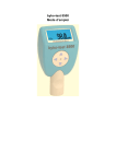
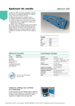
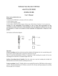
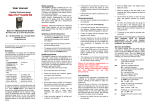
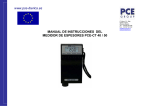
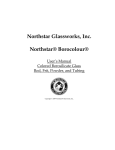
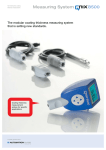
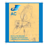
4
Technical Data
Instruction Manual
System Description
®
Substrate
Iron or steel
®
QuaNix 4500 includes:
Non-magnetic metals, e.g.
aluminum, zinc, copper, brass
Fe-probe
NFe-Probe
Measuring range
Resolution
resp.
Accuracy
Minimum object size
Minimum curvature
convex
concave
Minimum substrate
thickness
resp.
Fe
NFe
0 - 999 µm or 0.00 - 40 mil
1 µm
0.01 mil up to 9.99 mil
0.1 mil from 10 to 40 mil
+/- (2 µm + 3%)
+/- (0.08 mil + 3 %)
10 x 10 mm² (0.4"x0.4")
6x6 mm² (0.24"x0.24")
5 mm (0.02")
30 mm (1")
Fe
NFe
Temperature range
Storage
Operation
Probe
Power supply
Dimensions
ca.
Weight
ca.
0.20 mm (8 mil)
0.05 mm (2 mil)
-10°C to 60°C (14°F to 140°F)
0°C to 60°C (32°F to 140°F)
One-point
2 batteries AA alkaline
100 x 62 x 27 mm
(3.9" x 2.4“ x 1.1“)
100 g (3.5 oz) incl. batteries
Internet: www.automation.de
E-Mail: [email protected]
The QuaNix 4200 dry film thickness gauge measures all non-magnetic
coatings such as lacquer, chromium, copper, zinc etc. on steel or iron.
®
The QuaNix 4500 dry film thickness gauge additionally measures all
insulating coatings such as lacquer, plastic, enamel, etc. on non-magnetic,
metallic substrates, e.g. on aluminium, copper, brass or non-magnetic steel.
Both gauges conform to national (DIN) and international (ISO, BS, ASTM)
standards:
DIN 50981, 50984
BS 5411 (3, 11), 3900 (C, 5)
ISO 2178, 2360, 2808
ASTM B499, D1400
General
This dry film thickness gauge was designed for various applications.
Despite its rugged design it should be handled correctly to insure proper
measurements at all time.
Do not let it drop and protect it from dirt, dust, humidity, chemicals and
aggressive vapours. After use please store the gauge in the protective
case.
As with all precision instruments large temperature variations can influence
the measuring result. Please avoid direct solar irradiation and temperature
shocks.
Due to the physical measuring principles the measurements can be
influenced by strong electromagnetic fields. Please stay away from e.g.
transformers, high voltage lines or discharge sources. Do not take
measurements on magnetized parts. Magnetic fields can affect the Femeasurements. Strong electromagnetic radiation can affect the NFemeasurements.
The housing is resistant against most solvents. Use a soft damp cloth to
clean the housing.
Proper results can only be achieved with clean probes. Please regularly
check the probe tips and remove any dirt and paint from the rubies
If the gauge is not used for a long period, please remove the batteries from
the gauge in order to prevent leakage that can damage the unit.
In case of a malfunction of the instrument please do not try to repair it on
your own. Our customer service will be happy to assist you.
2
Change of Batteries
3
Handling
The battery compartment is on the rear side of the gauge. The battery
should be exchanged when the "BAT"-sign appears on the right side of the
display. Additional readings can still be taken even with the “BAT”-indication
before the gauge shuts off.
Note! Empty batteries should be disposed of properly. If possible, please
use the appropriate method.
Place the gauge evenly on the object to be tested. The reading is
immediately shown on the display accompanied by a beep. Simultaneously
you will also receive the information, which measuring method, Fe or NFe,
is presently used in the gauge (important for gauges with Dual-Probe).
Change of Unit µm/mil
Display of the readings is factory preset to the unit which is common for the
user (generally in µm). To change the unit from µm to mil or vice versa,
place the gauge on any surface or simply take a measurement. While
holding it placed, press the button for at least 3 seconds. The display will
switch from one unit to the other.
If the gauge was placed incorrectly or lifted off before termination of the
measurement, or when being zeroed on a non-metallic substrate, an error
message “Err“ is displayed. Readings that exceed the measuring range are
indicated by the message “IΙFI” (infinite).
The gauge switches on automatically when being placed on the surface and
turns off automatically after about 10 seconds when no other measurement
is taken. For measurements on rods or tubes etc. align the “V”-groove along
the axis of the object to be tested.
Zero-Adjustment
Measurements with the Dual-Probe
A new zero-adjustment is required when using the gauge for the first time,
working with different materials, and after inserting a new battery. Place the
gauge on one of the zero plates in the case. For the Fe-probe please take
the steel plate; for the NFe-probe take the aluminum plate, when you want
to measure on aluminum; or use a suitable uncoated Fe- or NFe-substrate.
Please make sure the probe is placed perpendicular and evenly on the
surface of the zero plate or on your uncoated substrate. If the value
indicated is not within the basic tolerance, the gauge should be adjusted as
follows:
Place the gauge on the zero plate (substrate). Then press the button once.
On the display a control number appears and a beep sounds. Then lift off
the gauge at least 10 cm (4 inches) from the zero plate (substrate). A beep
sounds and another control number appears. Now the zero-adjustment is
completed.
When repeating measurements on the same spot, the reading may not
always be 0 µm or 0.00 mil, as the surface roughness, dirt, scratches etc.
might cause variances.
The QuaNix 4500 gauge combines both measuring methods for Fe and
NFe in one probe. Switching from Fe to NFe or vice versa is done as
follows:
®
Switch on the gauge. The current measuring method is displayed on the left
side of the LCD (e.g. Fe). Press the button for at least 3 seconds. The new
measuring method is shown on the left side of the LCD (e.g. NFe).
Display Messages
Fe
NFe
Err
IΙFI
BAT
=
=
=
=
=
measurement on ferrous materials (steel or iron)
measurement on non-ferrous substrates
handling error
wrong substrate, reading beyond measuring range
battery is getting week, please exchange
2
Change of Batteries
3
Handling
The battery compartment is on the rear side of the gauge. The battery
should be exchanged when the "BAT"-sign appears on the right side of the
display. Additional readings can still be taken even with the “BAT”-indication
before the gauge shuts off.
Note! Empty batteries should be disposed of properly. If possible, please
use the appropriate method.
Place the gauge evenly on the object to be tested. The reading is
immediately shown on the display accompanied by a beep. Simultaneously
you will also receive the information, which measuring method, Fe or NFe,
is presently used in the gauge (important for gauges with Dual-Probe).
Change of Unit µm/mil
Display of the readings is factory preset to the unit which is common for the
user (generally in µm). To change the unit from µm to mil or vice versa,
place the gauge on any surface or simply take a measurement. While
holding it placed, press the button for at least 3 seconds. The display will
switch from one unit to the other.
If the gauge was placed incorrectly or lifted off before termination of the
measurement, or when being zeroed on a non-metallic substrate, an error
message “Err“ is displayed. Readings that exceed the measuring range are
indicated by the message “IΙFI” (infinite).
The gauge switches on automatically when being placed on the surface and
turns off automatically after about 10 seconds when no other measurement
is taken. For measurements on rods or tubes etc. align the “V”-groove along
the axis of the object to be tested.
Zero-Adjustment
Measurements with the Dual-Probe
A new zero-adjustment is required when using the gauge for the first time,
working with different materials, and after inserting a new battery. Place the
gauge on one of the zero plates in the case. For the Fe-probe please take
the steel plate; for the NFe-probe take the aluminum plate, when you want
to measure on aluminum; or use a suitable uncoated Fe- or NFe-substrate.
Please make sure the probe is placed perpendicular and evenly on the
surface of the zero plate or on your uncoated substrate. If the value
indicated is not within the basic tolerance, the gauge should be adjusted as
follows:
Place the gauge on the zero plate (substrate). Then press the button once.
On the display a control number appears and a beep sounds. Then lift off
the gauge at least 10 cm (4 inches) from the zero plate (substrate). A beep
sounds and another control number appears. Now the zero-adjustment is
completed.
When repeating measurements on the same spot, the reading may not
always be 0 µm or 0.00 mil, as the surface roughness, dirt, scratches etc.
might cause variances.
The QuaNix 4500 gauge combines both measuring methods for Fe and
NFe in one probe. Switching from Fe to NFe or vice versa is done as
follows:
4
Technical Data
Display Messages
Fe
NFe
Err
IΙFI
BAT
=
=
=
=
=
measurement on ferrous materials (steel or iron)
measurement on non-ferrous substrates
handling error
wrong substrate, reading beyond measuring range
battery is getting week, please exchange
Instruction Manual
®
Fe-probe
NFe-Probe
Measuring range
Resolution
resp.
Accuracy
Minimum curvature
convex
concave
Minimum substrate
thickness
Switch on the gauge. The current measuring method is displayed on the left
side of the LCD (e.g. Fe). Press the button for at least 3 seconds. The new
measuring method is shown on the left side of the LCD (e.g. NFe).
System Description
Substrate
Iron or steel
®
QuaNix 4500 includes:
Non-magnetic metals, e.g.
aluminum, zinc, copper, brass
Minimum object size
®
resp.
Fe
NFe
0 - 999 µm or 0.00 - 40 mil
1 µm
0.01 mil up to 9.99 mil
0.1 mil from 10 to 40 mil
+/- (2 µm + 3%)
+/- (0.08 mil + 3 %)
10 x 10 mm² (0.4"x0.4")
6x6 mm² (0.24"x0.24")
5 mm (0.02")
30 mm (1")
Fe
NFe
Temperature range
Storage
Operation
Probe
Power supply
Dimensions
ca.
Weight
ca.
0.2 mm (8 mil)
0.05 mm (2 mil)
-10°C to 60°C (14°F to 140°F)
0°C to 60°C (32°F to 140°F)
One-point
2 batteries AA alkaline
100 x 62 x 27 mm
(3.9" x 2.4“ x 1.1“)
100 g (3.5 oz) incl. batteries
Internet: www.automation.de
E-Mail: [email protected]
The QuaNix 4200 dry film thickness gauge measures all non-magnetic
coatings such as lacquer, chromium, copper, zinc etc. on steel or iron.
®
The QuaNix 4500 dry film thickness gauge additionally measures all
insulating coatings such as lacquer, plastic, enamel, etc. on non-magnetic,
metallic substrates, e.g. on aluminium, copper, brass or non-magnetic steel.
Both gauges conform to national (DIN) and international (ISO, BS, ASTM)
standards:
DIN 50981, 50984
BS 5411 (3, 11), 3900 (C, 5)
ISO 2178, 2360, 2808
ASTM B499, D1400
General
This dry film thickness gauge was designed for various applications.
Despite its rugged design it should be handled correctly to insure proper
measurements at all time.
Do not let it drop and protect it from dirt, dust, humidity, chemicals and
aggressive vapours. After use please store the gauge in the protective
case.
As with all precision instruments large temperature variations can influence
the measuring result. Please avoid direct solar irradiation and temperature
shocks.
Due to the physical measuring principles the measurements can be
influenced by strong electromagnetic fields. Please stay away from e.g.
transformers, high voltage lines or discharge sources. Do not take
measurements on magnetized parts. Magnetic fields can affect the Femeasurements. Strong electromagnetic radiation can affect the NFemeasurements.
The housing is resistant against most solvents. Use a soft damp cloth to
clean the housing.
Proper results can only be achieved with clean probes. Please regularly
check the probe tips and remove any dirt and paint from the rubies
If the gauge is not used for a long period, please remove the batteries from
the gauge in order to prevent leakage that can damage the unit.
In case of a malfunction of the instrument please do not try to repair it on
your own. Our customer service will be happy to assist you.