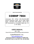
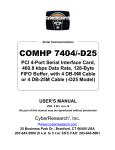
1
®
Serial Communications
COMHP 7801 Series
PCI Serial Interface Card with 8 RS232 Ports & 8 DB-25M or 8 DB-9M
Connectors
COMHP 7801: 16554 UART
COMHP 7801-E: 16854 UART
COMHP 7801-X: 16C950 UART
USER’S MANUAL
VER. 1.1 • 2001
No part of this manual may be reproduced without permission
®
CyberResearch , Inc.
www.cyberresearch.com
25 Business Park Dr., Branford, CT 06405 USA
203-483-8815 (9am to 5pm EST) FAX: 203-483-9024
©Copyright 2001 CyberResearch, Inc.
All Rights Reserved.
The information in this document is subject to change without prior notice in order to
improve reliability, design, and function and does not represent a commitment on the
part of CyberResearch, Inc.
In no event will CyberResearch, Inc. be liable for direct, indirect, special, incidental, or
consequential damages arising out of the use of or inability to use the product or
documentation, even if advised of the possibility of such damages.
This document contains proprietary information protected by copyright. All rights are
reserved. No part of this manual may be reproduced by any mechanical, electronic,
or other means in any form without prior written permission of CyberResearch, Inc.
TRADEMARKS
“CyberResearch” and “COMHP 7801” are trademarks of CyberResearch, Inc. Other
product names mentioned herein are used for identification purposes only and may
be trademarks and/or registered trademarks of their respective companies.
• NOTICE •
CyberResearch, Inc. does not authorize any CyberResearch product for use in life
support systems, medical equipment, and/or medical devices without the written
approval of the President of CyberResearch, Inc. Life support devices and systems
are devices or systems which are intended for surgical implantation into the body, or
to support or sustain life and whose failure to perform can be reasonably expected to
result in injury. Other medical equipment includes devices used for monitoring, data
acquisition, modification, or notification purposes in relation to to life support, life
sustaining, or vital statistic recording. CyberResearch products are not designed with
the components required, are not subject to the testing required, and are not submitted
to the certification required to ensure a level of reliability appropriate for the treatment
and diagnosis of humans.
CyberResearch
COMHP 7801
Page i
Contents
INTRODUCTION ..................................................................... 1
OVERVIEW .................................................................................. 1
WHAT’S INCLUDED ..................................................................... 1
CARD SETUP ......................................................................... 2
CLOCK MODES............................................................................ 2
BAUD RATES AND DIVISORS FOR THE ‘DIV1’ MODE....................... 3
ADDRESS AND IRQ SELECTION .................................................... 3
INSTALLATION ...................................................................... 4
OPERATING SYSTEM INSTALLATION ............................................. 4
For Windows Users ................................................................. 4
Other Operating Systems......................................................... 4
SYSTEM INSTALLATION ............................................................... 4
TECHNICAL DESCRIPTION .................................................... 5
CONNECTOR PIN ASSIGNMENTS ................................................... 5
DB-25 (RS-232 DTE) (DB25 MALE).................................. 5
DB-9 (EIA-574 DTE) (DB9 MALE) .................................... 5
DB-78 CONNECTOR PIN ASSIGNMENTS
(DB78 FEMALE) ... 6
SPECIFICATIONS ................................................................... 7
ENVIRONMENTAL SPECIFICATIONS ............................................... 7
POWER CONSUMPTION ................................................................ 7
MEAN TIME BETWEEN FAILURES (MTBF).................................... 7
PHYSICAL DIMENSIONS ............................................................... 7
APPENDIX A - TROUBLESHOOTING ...................................... 8
PCI COM NUMBER SELECTION IN WINDOWS 95 .............. 9
APPENDIX B - HOW TO GET ASSISTANCE .......................... 10
APPENDIX C - ELECTRICAL INTERFACE ............................ 11
RS-232..................................................................................... 11
APPENDIX D - ASYNCHRONOUS COMMUNICATIONS .......... 12
APPENDIX E - SILK-SCREEN ............................................... 13
APPENDIX F - COMPLIANCE NOTICES ................................ 14
FEDERAL COMMUNICATIONS COMMISSION STATEMENT .............. 14
EMC DIRECTIVE STATEMENT ................................................... 14
WARRANTY ......................................................................... 16
Figures
Figure 1 - Clocking Mode ‘Divide By 4’ ............................................... 2
Figure 2 - Clocking Mode ‘Divide By 1’ ............................................... 2
Figure 3 - Asynchronous Communications Bit Diagram .................... 12
Introduction
Introduction
Overview
The CyberResearch COMHP 7801 provides the PC with eight RS-232
asynchronous ports. The COMHP 7801 allows for connection to any device
utilizing the RS-232 electrical interface, such as modems, data-entry terminals,
and plotters.
What’s Included
The COMHP 7801 is shipped with the following items. If any of these items
is missing or damaged, contact the supplier.
•
•
•
•
COMHP 7801 Serial I/O Adapter
DB-78 to eight DB-25 ‘Spider Cable’ (DB-9 Spider Cable is
available)
Serial Utility Software
User Manual
CyberResearch COMHP 7801
Page 1
Intentionally Blank
Card Setup
Card Setup
Clock Modes
The COMHP 7801 employs a unique clocking option that allows the end user
to select from divide by 4 and divide by 1 clocking modes. This mode is
selected at J1.
DIV1
DIV4
To select the Baud rates commonly associated with COM: ports (i.e. 2400,
4800, 9600, 19.2, … 115.2K Bps) place the jumper in the divide by 4 mode
(silk-screen DIV4).
Figure 1 - Clocking Mode ‘Divide By 4’
DIV1
DIV4
To select the maximum data rate (460.8K bps) place the jumper in the divide
by 1 (silk-screen DIV1) position.
Figure 2 - Clocking Mode ‘Divide By 1’
CyberResearch COMHP 7801
Page 2
Card Setup
Baud Rates and Divisors for the ‘Div1’ mode
The following table shows some common data rates and the rates you should
choose to match them if using the adapter in the ‘Div1’ mode.
For this Data Rate
1200 bps
2400 bps
4800 bps
9600 bps
19.2K bps
57.6 K bps
115.2 K bps
230.4K bps
460.8K bps
Choose this Data Rate
300 bps
600 bps
1200 bps
2400 bps
4800 bps
14.4K bps
28.8K bps
57.6 K bps
115.2 K bps
If your communications package allows the use of Baud rate divisors, choose
the appropriate divisor from the following table:
For this Data Rate
1200 bps
2400 bps
4800 bps
9600 bps
19.2K bps
38.4K bps
57.6K bps
115.2K bps
230.4K bps
460.8K bps
Choose this Divisor
384
192
96
48
24
12
8
4
2
1
Address and IRQ selection
The COMHP 7801 is automatically assigned I/O addresses and IRQs by your
motherboard BIOS. Only the I/O address may be modified by the user.
Adding or removing other hardware may change the assignment of I/O
addresses and IRQs.
CyberResearch COMHP 7801
Page 3
Installation
Installation
Operating System Installation
For Windows Users
Start by choosing Install Software at the beginning of the CD.
Choose Asynchronous COM: Port Software, SeaCOM.
Other Operating Systems
Refer to the appropriate section of the Serial Utilities Software.
System Installation
The COMHP 7801 can be installed in any of the PCI expansion slots and
contains a single jumper strap that must be set for proper operation. Please see
the Card Setup section of the manual for information on this jumper.
1.
2.
3.
4.
5.
6.
7.
Turn off PC power. Disconnect the power cord.
Remove the PC case cover.
Locate an available PCI slot and remove the blank metal slot cover.
Gently insert the COMHP 7801 into the slot. Make sure that the adapter
is seated properly.
Replace the screw.
Replace the cover.
Connect the power cord.
Installation is complete.
CyberResearch COMHP 7801
Page 4
Intentionally Blank
Technical Description
Technical Description
The COMHP 7801 utilizes the 16C554 UART. This chip features
programmable baud rate, data format, interrupt control and a 16-byte input and
output FIFO, and is functionally 4 16C550 UARTs. A full array of advanced
UARTS is also available for this card. Contact CyberResearch for more
information.
Connector Pin Assignments
DB-25 (RS-232 DTE)
Signal
GND
TD
RTS
DTR
RD
CTS
DSR
DCD
RI
Name
Ground
Transmit Data
Request To Send
Data Terminal Ready
Receive Data
Clear To Send
Data Set Ready
Data Carrier Detect
Ring Indicator
DB-9 (EIA-574 DTE)
Signal
GND
TD
RTS
DTR
RD
CTS
DSR
DCD
RI
(DB25 MALE)
Pin #
7
2
4
20
3
5
6
8
22
Mode
Output
Output
Output
Input
Input
Input
Input
Input
(DB9 MALE)
Name
Ground
Transmit Data
Request To Send
Data Terminal Ready
Receive Data
Clear To Send
Data Set Ready
Data Carrier Detect
Ring Indicator
Pin #
5
3
7
4
2
8
6
1
9
Mode
Output
Output
Output
Input
Input
Input
Input
Input
Technical Note: Please terminate any control signals that are not going to be
used. The most common way to do this is connect RTS to CTS and RI. Also,
connect DCD to DTR and DSR. Terminating these pins, if not used, will help
insure
you
get
the
best
performance
from
your
adapter.
CyberResearch COMHP 7801
Page 5
Technical Description
DB-78 Connector Pin Assignments
Port #
TD
RD
RTS
CTS
DTR
DSR
DCD
RI
GND
1
36
37
17
16
35
18
38
15
34
2
12
11
31
32
13
30
10
33
14
CyberResearch COMHP 7801
3
27
28
8
7
26
9
29
6
25
4
3
2
22
23
4
21
1
24
5
(DB78 FEMALE)
5
75
76
56
55
74
57
77
54
73
6
51
50
70
71
52
69
49
72
53
7
66
67
47
46
65
48
68
45
64
8
42
41
61
62
43
60
40
63
44
Page 6
Specifications
Specifications
Environmental Specifications
Specification
Temperature
Range
Humidity Range
Operating
0º to 50º C
(32º to 122º F)
10 to 90% R.H.
Non-Condensing
Storage
-20º to 70º C
(-4º to 158º F)
10 to 90% R.H.
Non-Condensing
Power Consumption
Supply line
Rating
+12 VDC
60 mA
-12 VDC
100 mA
+5 VDC
295 mA
Mean Time Between Failures (MTBF)
Greater than 150,000 hours. (Calculated)
Physical Dimensions
Board length
Board Height including Goldfingers
Board Height excluding Goldfingers
CyberResearch COMHP 7801
5.650 inches
3.8 inches
3.475 inches
(14.351 cm.)
(9.652 cm.)
(8.827 cm.)
Page 7
Intentionally Blank
Appendix A - Troubleshooting
Appendix A - Troubleshooting
Serial Utility test software is supplied with the CyberResearch adapter and
will be used in the troubleshooting procedures. By using this software and
following these simple steps, most common problems can be eliminated without
the need to call Technical Support.
1.
Identify all I/O adapters currently installed in your system. This includes
your on-board serial ports, controller cards, sound cards etc. The I/O
addresses used by these adapters, as well as the IRQ (if any) should be
identified.
2.
Configure your CyberResearch adapter so that there is no conflict with
currently installed adapters. No two adapters can occupy the same I/O
address.
3.
Make sure the CyberResearch adapter is securely installed in a
motherboard slot.
4.
When running DOS, Windows 3.x or other operating systems refer to the
Serial Utilities software for that operating system and the User Manual to
verify that the CyberResearch adapter is configured correctly. The
supplied software contains a diagnostic program 'SSD' that runs under
DOS and will verify if an adapter is configured properly. This diagnostic
program is written with the user in mind and is easy to use. Refer to the
DIAG.txt file in the dos\diag directory for detailed instructions on using
'SSD'.
5.
For Windows 95/98 and Windows NT, the diagnostic tool 'WinSSD' is
installed in the CyberResearch folder on the Start Menu during the setup process.
First find the ports using the Device Manager, then use 'WinSSD' to verify
that the ports are functional.
6.
Always use the CyberResearch diagnostic software when troubleshooting
a problem. This will help eliminate any software issues and identify any
hardware conflicts.
CyberResearch COMHP 7801
Page 8
Appendix A - Troubleshooting
PCI COM NUMBER SELECTION IN WINDOWS 95
When installing a multi-port PCI card in Windows 95 the default starting
COM: number assigned to the first port will be COM:5 if no COM:5 exists. If
there is a COM: 5, 6, etc., the next available COM: number will be assigned to
the first port with all additional ports following in ascending order.
To change the first two ports so that Windows assigns them COM: 3 and COM:
4 port enumeration double click the Systems icon in control panel or right click
on My Computer and choose properties which will bring you to System
Properties. Choose the Device Manager tab and double click on the MultiFunction Adapter heading. This will show all the information concerning the
CyberResearch adapter. Choose the Resources tab, which will show all resources
assigned to the multi-function adapter. Uncheck the Use Automatic Settings
box. Notice that with a two port card there will be three input/output, (I/O),
ranges listed. With a four port card there will be five input/output, (I/O), ranges
listed. The first I/O range is for the PCI bus and should not be changed. The
second and third I/O ranges are the ones that need to be changed in order to
have those ports enumerated as COM: 3 and COM: 4. Double click on the
second I/O range which will allow you to change the address. Highlight the
entire I/O range and type: 03e8–03ef for COM: 3. Click OK. Windows will
inform you that you have made modifications that may affect other devices.
Click OK. Next double click on the third I/O range. Highlight the entire I/O
range and type: 02e8–02ef for COM: 4. Again Windows will inform you that
you have made modifications that may affect other devices. Click OK.
Following these steps will change the COM: number assignments on the first
two ports to
COM: 3 and 4.
CyberResearch COMHP 7801
Page 9
Appendix B - How To Get Assistance
Appendix B - How To Get Assistance
Please refer to Troubleshooting Guide prior to calling Technical Support.
1.
Read this manual thoroughly before attempting to install the
adapter in your system.
2.
When calling for technical assistance, please have your user
manual and current adapter settings. If possible, please have the
adapter installed in a computer ready to run diagnostics.
3.
CyberResearch maintains a Home page on the Internet. Our
home page address is www.cyberresearch.com. The latest software
updates, and newest manuals are available via our FTP site that
can be accessed from our home page.
4.
Technical support is available Monday to Friday from 9:00 a.m. to
5:00 p.m. eastern time. Technical support can be reached at (800)
341-2525.
RETURN AUTHORIZATION MUST BE OBTAINED FROM
CYBERRESAERCH SYSTEMS BEFORE RETURNED MERCHANDISE WILL
BE ACCEPTED. AUTHORIZATION CAN BE OBTAINED BY
CALLING CYBERRESEARCH AND REQUESTING A RETURN
MERCHANDISE AUTHORIZATION (RMA) NUMBER.
CyberResearch COMHP 7801
Page 10
Appendix C - Electrical Interface
Appendix C - Electrical Interface
RS-232
Quite possibly the most widely used communication standard is RS-232. This
implementation has been defined and revised several times and is often referred
to as RS-232-C/D/E or EIA/TIA-232-C/D/E. It is defined as “Interface between
Data Terminal Equipment and Data Circuit- Terminating Equipment
Employing Serial Binary Data Interchange”. The mechanical implementation
of RS-232 is on a 25-pin D sub connector. The IBM PC computer defined the
RS-232 port on a 9 pin D sub connector and subsequently the EIA/TIA
approved this implementation as the EIA/TIA-574 standard. This standard has
defined as the “9-Position Non-Synchronous Interface between Data Terminal
Equipment and Data Circuit-Terminating Equipment Employing Serial Binary
Data Interchange”. Both implementations are in wide spread use and will be
referred to as RS-232 in this document. RS-232 is capable of operating at data
rates up to 20K bps / 50 ft. The absolute maximum data rate may vary due to
line conditions and cable lengths. RS-232 often operates at 38.4K bps over very
short distances. The voltage levels defined by RS-232 range from -12 to +12
volts. RS-232 is a single ended or unbalanced interface, meaning that a single
electrical signal is compared to a common signal (ground) to determine binary
logic states. A voltage of +12 volts (usually +3 to +10 volts) represents a binary
0 (space) and -12 volts (-3 to -10 volts) denote a binary 1 (mark). The RS-232
and the EIA/TIA-574 specification define two types of interface circuits Data
Terminal Equipment (DTE) and Data Circuit-Terminating Equipment (DCE).
The CyberResearch Adapter is a DTE interface.
CyberResearch COMHP 7801
Page 11
Appendix D - Asynchronous Communications
Appendix D - Asynchronous Communications
Serial data communications implies that individual bits of a character are
transmitted consecutively to a receiver that assembles the bits back into a
character. Data rate, error checking, handshaking, and character framing
(start/stop bits) are pre-defined and must correspond at both the transmitting
and receiving ends.
Asynchronous communications is the standard means of serial data
communication for PC compatibles and PS/2 computers. The original PC was
equipped with a communication or COM: port that was designed around an
8250 Universal Asynchronous Receiver Transmitter (UART). This device
allows asynchronous serial data to be transferred through a simple and
straightforward programming interface. A starting bit followed by a pre-defined
number of data bits (5, 6, 7, or 8) defines character boundaries for
asynchronous communications. The end of the character is defined by the
transmission of a pre-defined number of stop bits (usually 1, 1.5 or 2). An extra
bit used for error detection is often appended before the stop bits.
Idle state of
line
Odd, Even
5 to 8 Data Bits
or
Unused
Remain Idle or
next start bit
1
P
BIT
STOP
0
1
1.5
2
Figure 3 - Asynchronous Communications Bit Diagram
This special bit is called the parity bit. Parity is a simple method of determining
if a data bit has been lost or corrupted during transmission. There are several
methods for implementing a parity check to guard against data corruption.
Common methods are called (E)ven Parity or (O)dd Parity. Sometimes parity is
not used to detect errors on the data stream. This is refereed to as (N)o parity.
Because each bit in asynchronous communications is sent consecutively, it is
easy to generalize asynchronous communications by stating that each character
is wrapped (framed) by pre-defined bits to mark the beginning and end of the
serial transmission of the character. The data rate and communication
parameters for asynchronous communications have to be the same at both the
transmitting and receiving ends. The communication parameters are baud rate,
parity, number of data bits per character, and stop bits (i.e. 9600,N,8,1).
CyberResearch COMHP 7801
Page 12
Appendix E - Silk-Screen
Appendix E - Silk-Screen
3.8"
5.650"
3.475"
CyberResearch COMHP 7801
Page 13
Appendix F - Compliance Notices
Appendix F - Compliance Notices
Federal Communications Commission Statement
FCC - This equipment has been tested and found to comply with the limits for
Class A digital device, pursuant to Part 15 of the FCC Rules. These limits are
designed to provide reasonable protection against harmful interference when
the equipment is operated in a commercial environment. This equipment
generates, uses, and can radiate radio frequency energy and, if not installed and
used in accordance with the instruction manual, may cause harmful
interference to radio communications. Operation of this equipment in a
residential area is likely to cause harmful interference in such case the user will
be required to correct the interference at his own expense.
EMC Directive Statement
Products bearing the CE Label fulfill the requirements of the
EMC directive (89/336/EEC) and of the low-voltage directive
(73/23/EEC) issued by the European Commission.
To obey these directives, the following European standards must be met:
•
EN55022 Class A - “Limits and methods of measurement of radio
interference characteristics of information technology equipment”
•
EN50082-1 - “Electromagnetic compatibility - Generic immunity
standard” Part 1 : Residential, commercial and light industry
•
EN60950 (IEC950) - “Safety of information
equipment, including electrical business equipment”
technology
Warning
This is a Class A Product. In a domestic environment this product may
cause radio interference in which case the user may be required to take
adequate measures.
Always use cabling provided with this product if possible. If no cable is
provided or if an alternate cable is required, use high quality shielded cabling to
maintain compliance with FCC/EMC directives.
CyberResearch COMHP 7801
Page 14
Product Service
Product Service
Diagnosis and Debug
CyberResearch, Inc. maintains technical support lines staffed by experienced
Applications Engineers and Technicians. There is no charge to call and we will
return your call promptly if it is received while our lines are busy. Most
problems encountered with data acquisition products can be solved over the
phone. Signal connections and programming are the two most common sources
of difficulty. CyberResearch support personnel can help you solve these
problems, especially if you are prepared for the call.
To ensure your call’s overall success and expediency:
1)
Have the phone close to the PC so you can conveniently and quickly
take action that the Applications Engineer might suggest.
2)
Be prepared to open your PC, remove boards, report back-switch or
jumper settings, and possibly change settings before reinstalling the
modules.
3)
Have a volt meter handy to take measurements of the signals you are
trying to measure as well as the signals on the board, module, or power
supply.
4)
Isolate problem areas that are not working as you expected.
5)
Have the source code to the program you are having trouble with
available so that preceding and prerequisite modes can be referenced and
discussed.
6)
Have the manual at hand. Also have the product’s utility disks and
any other relevant disks nearby so programs and version numbers can
be checked.
Preparation will facilitate the diagnosis procedure, save you time, and avoid
repeated calls. Here are a few preliminary actions you can take before you call
which may solve some of the more common problems:
1)
2)
3)
4)
Check the PC-bus power and any power supply signals.
Check the voltage level of the signal between SIGNAL HIGH and
SIGNAL LOW, or SIGNAL+ and SIGNAL– . It CANNOT exceed the
full scale range of the board.
Check the other boards in your PC or modules on the network for
address and interrupt conflicts.
Refer to the example programs as a baseline for comparing code
CyberResearch, Inc x COMHP 7801
Page 15
Warranty Notice
Warranty Notice
CyberResearch, Inc. warrants that this equipment as furnished will be free from
defects in material and workmanship for a period of one year from the confirmed
date of purchase by the original buyer and that upon written notice of any such
defect, CyberResearch, Inc. will, at its option, repair or replace the defective
item under the terms of this warranty, subject to the provisions and specific
exclusions listed herein.
This warranty shall not apply to equipment that has been previously repaired or
altered outside our plant in any way which may, in the judgment of the
manufacturer, affect its reliability. Nor will it apply if the equipment has been
used in a manner exceeding or inconsistent with its specifications or if the serial
number has been removed.
CyberResearch, Inc. does not assume any liability for consequential damages
as a result from our products uses, and in any event our liability shall not
exceed the original selling price of the equipment.
The equipment warranty shall constitute the sole and exclusive remedy of any
Buyer of Seller equipment and the sole and exclusive liability of the Seller, its
successors or assigns, in connection with equipment purchased and in lieu of all
other warranties expressed implied or statutory, including, but not limited to,
any implied warranty of merchant ability or fitness and all other obligations or
liabilities of seller, its successors or assigns.
The equipment must be returned postage prepaid. Package it securely and insure
it. You will be charged for parts and labor if the warranty period has expired.
Returns and RMAs
If a CyberResearch product has been diagnosed as being non-functional, is
visibly damaged, or must be returned for any other reason, please call for an
assigned RMA number. The RMA number is a key piece of information that
lets us track and process returned merchandise with the fastest possible
turnaround time.
PLEASE CALL FOR AN RMA NUMBER!
Packages returned without an RMA number will be refused!
In most cases, a returned package will be refused at the receiving dock if its
contents are not known. The RMA number allows us to reference the history of
returned products and determine if they are meeting your application’s
requirements. When you call customer service for your RMA number, you will
be asked to provide information about the product you are returning, your
address, and a contact person at your organization.
Please make sure that the RMA number
is prominently displayed on the outside of the box.
• Thank You •
CyberResearch, Inc x COMHP 7801
Page 16
Intentionally Blank