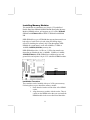
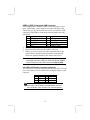
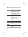
1
Pin
1
3
5
7
9
Signal
HD_LED_P
HD_LED_N
RESET_SW_N
RESET_SW_P
RSVD_DNU
Pin
2
4
6
8
10
Signal
FP PWR/SLP
FP PWR/SLP
POWER_SW_P
POWER_SW_N
KEY
Connecting Optional Devices
Refer to the following for information on connecting the
mainboard’s optional devices:
1
J6
1
1
AUDIO1
1
SIR1
1
USB3
1
USB2
SPK1
SPK1: Speaker Connector
Connect the cable from the PC speaker to the SPK1 connector on
the mainboard.
Pin
1
3
Signal
SPKR
GND
Pin
2
4
Signal
NC
+5V
AUDIO1: Front Panel Audio Connector
This header allows the user to install auxiliary front-oriented
microphone and line-out ports for easier access.
Here is a list of AUDIO1 connector pin assignment.
Pin
1
AUD_MIC
Signal
Pin
2
AUD_GND
3
5
7
9
AUD_MIC_BIAS
AUD_FPOUT_R
HP_ON
AUD_FPOUT_L
4
6
8
10
AUD_VCC
AUD_RET_R
KEY
AUD_RET_L
14
Signal