1
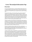
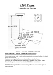
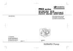
Leader in
Level Measurement
Technical Assistance: 1-800-527-6297
Outside North America: +1-215-674-1234
Installation and
Operating Instructions
DM330 Series
Magnetostrictive Level System
U.S. and Canada:
1-800-553-9092
24-Hour Service:
1-800-527-6297
International:
+1 215-674-1234
Fax:
+1 215-674-2731
E-mail:
[email protected]
Website:
www.drexelbrook.com
AMETEK Drexelbrook makes no warranty of any kind with regard to the material contained
in this manual, including, but not limited to, implied warranties or fitness for a particular
purpose. Drexelbrook shall not be liable for errors contained herein or for incidental or
consequential damages in connection with the performance or use of material.
Copyright 2007 AMETEK Drexelbrook
EDO #01-07-123
DM33X-LM
Issue #8
DM330 Series
Magnetostrictive Level System
An ISO 9001 Certified Company
205 Keith Valley Road, Horsham, PA 19044
U.S. and Canada:
1-800-553-9092
24-Hour Service:
1-800-527-6297
International:
+1 215-674-1234
Fax:
+1 215-674-2731
E-mail:
[email protected]
Website:
www.drexelbrook.com
Contents
Section 1:
1.1
1.2
1.3
1.4
1.5
1.6
1.7
1.8
Introduction.................................................................................................1
Product Description......................................................................................1
Terminology..................................................................................................1
Technology....................................................................................................2
Model Numbering - Explosion-Proof.............................................................3
Model Numbering - Intrinsically Safe............................................................4
Probe Dimensions - Inches (mm).................................................................5
Sanitary Probe Dimensions - Inches (mm)...................................................5
Float Dimensions & Types - Inches (mm).....................................................5
Section 2:
2.1
2.2
2.3
2.4
2.5
2.6
2.7
2.8
2.9
Installation...................................................................................................7
Unpacking.....................................................................................................7
Mounting Conditions....................................................................................9
Mounting Considerations..............................................................................11
Stainless Steel Probe Mounting....................................................................11
Flexible Polyvinylidene Fluoride (PVDF) Probe Mounting.............................14
Mounting Optional Housing .........................................................................19
Wiring............................................................................................................20
Loop Configuration of 4mA & 20mA Control Points......................................23
Correlating Level...........................................................................................25
Section 3: Operation.....................................................................................................27
Section 4:
4.1
4.2
4.3
4.4
4.5
4.6
4.7
Troubleshooting..........................................................................................29
Symptom Chart.............................................................................................29
Internal Diagnostics......................................................................................29
Automatic Gain Control (AGC)......................................................................30
Factory Assistance........................................................................................31
Field Service.................................................................................................31
Customer Training.........................................................................................31
Equipment Return.........................................................................................32
Section 5: Specifications..............................................................................................33
Section 6: Approvals.....................................................................................................35
Section 7: Control Drawings........................................................................................37
Section 1
Introduction
Section 1: Introduction
1.1
Product Description
The AMETEK Drexelbrook DM330 Series Magnetostrictive
Level System is an integral assembly that measures linear
motion or liquid level using magnetostrictive technology. A
single level output is provided with configurable 4 and 20mA
points in an intrinsically safe, standard two wired loop-powered
configuration.
Unlike conventional level instruments the electronics are
incorporated into the measuring probe and there is no external
electronic housing. This design utilizes sophisticated Surface
Mount Technology (SMT) integrated into a 5/8” diameter tube,
reducing user's cost and offers greater options for insertion
and mounting. The self-contained unit provides IP68 or Nema
4X protection in either rigid 316 stainless steel or flexible
Polyvinylidene Fluoride (PVDF).
There are several reasons for using a flexible PVDF probe
instead of a rigid stainless steel probe:
Limited Headroom: There may be limited space available above
a tank, making it impossible to install a rigid probe without
damaging the probe.
Chemical Compatibility: When an application is not compatible
with 316 SS, then PVDF may be a good alternative.
Large Tanks: Since the 316 SS probe maximum length is 24
feet, PVDF can be substituted for larger tanks. PVDF probes
are available in lengths up to 40 feet. Consult factory for longer
lengths
Other standard options include a quick disconnect miniconnector or ¾” NPT conduit connection. An optional housing
is available which includes terminal connectors and adjustors
for zero & span.
A variety of floats and mounting accessories are available to
fit nearly all applications. The sanitary stainless steel version
features all welded and polished construction with 180 grit for
food service or 240 grit, ground, and Polished finish for more
stringent sanitary applications.
1.2
Terminology
Magnetostriction: A magnetic field produces small change in
the physical dimension of ferromagnetic materials on the order
of several parts per million in carbon steel and conversely, a
physical deformation or stain (torsion) produces a change of
magnetization in the material.
DM330 Series - Magnetostrictive Level System User's Manual
1.3
Technology
In a magnetostrictive level sensor a current pulse is sent down a
wave guide made of a special nickel alloy wire designed to enhance
magnetostrictive properties. A permanent magnet within a float
is used to indicate the position or level being measured. The
interaction of the current pulse with the magnetic field created by a
float (with magnet) produces a torsional strain pulse that travels at
approximately the speed of sound along the wire. A small induction
pickup coil senses the strain pulse. The position of the float is
determined with high precision by measuring the time between the
launching of the current pulse and the arrival of the torsional strain
pulse.
The magnetostrictive wire is linearized during manufacture and
the speed of the torsional pulse is determined for the specific sensor.
Inherently, magnetostrictive sensors have very high resolution and
repeatability.
Magnetostrictive technology is excellent as well for applications where
the dielectric constant is very low or is changing. The technology has
been used quite successfully for the detection of leaks in underground
storage tanks, for example. The measurement of a 0.1 gallon leak
out of a 10,000 gallon tank over a period of one hour is the standard
for EPA mandated leak detection.
A Current Interrogation Pulse creates an
electromagnetic field along the Magnetostrictive wire.
Permanent Magnet in Float
Reflector
Magnetostrictive wire within tube...
pulse
t1
t2
reaction pulses
Strikes field of permanent magnet & creates a torsional strain pulse
or wave guide twist.
...causing two torsional strain pulses to travel in each direction along
wire (the wave guide) at approximately the speed of sound.
Permanent Magnet in Float
Reflector
Magnetostrictive wire within tube...
t1
t2
t2
t1-t2
Time between initial pulse t 1 and second t 2 reflected return pulse
is used to determine float position & level.
Figure 1-1
Magnetostrictive Theory
Introduction
1.4
Model Numbering - Explosion-Proof
See section 6 for Explosion-Proof Approval Information
Magnetostrictive Level Measurement system
DM330
Probe Style / Material
X
316SS
Connector Style
D
Dual 3/4" NPT - for both housing and vessel mounting
S
Single 3/4" NPT - for housing mounting, vessel mtg. via compression fitting, flange or triclamp
Thread Mounting
E
English Units - 3/4" NPT with Connector Style D or S
Overall Length
XXX (in inches only)
Output Signal
F1
1 Signal Output
Float 1 Type
XXX -- See Float in Chart below
Housing option
H
Condulet with Zero & Span push-buttons
Special Mounting
Y
Explosion proof Class I Div. 1, (FM & CSA)
Z
Flame proof for Zone 1 (ATEX pending)
Special Mounting (does not affect agency certification)
CF
Adjustable Compression Fitting
(5/8” tube fitting to 3/4” NPT)
XX
None
Float Kits
Float Type selection includes Float, spacer and retaining clip
Material
PU0
PN0
PK0
PE0
XXX
YYY
Shape Diameter Hight
S.G.
Max. Press.
Ureth.
Cylind 3.85"
2.75"
0.52
50psi
Nitrophyl
Round 2.02"
1.38"
0.4
300psi
PVDF
Oval
2.05"
2.40"
0.7
100psi
316SS
Oval
2.05"
2.7"
0.54
350psi
None
- Special Float / Float Kit ordered as a separate line item
DM330 Series - Magnetostrictive Level System User's Manual
1.5
Model Numbering - Intrinsically Safe
See section 6 for Intrinsically Safe Approval Information
Magnetostrictive Level Measurement system
DM330
Probe Style / Material
X
316SS
V
PVDF (Polyvinylidene Fluoride)
S
316SS 3A Sanitary 240 grit electropolished
F
316SS Food Grade 180 grit
Connector Style
M
Mini connector
D
Dual 3/4" NPT - for both housing and vessel mounting
S
Single 3/4" NPT - for housing mounting, vessel mtg. via compression fitting, flange or triclamp
R
Right Angle Connection - (1/2" NPT Electrical Connection)
Thread Mounting
E
English Units - 3/4" NPT with Connector Style D or S
Overall Length
XXX (in inches only, not to exceed 480 inches)
Output Signal
F1
1 Signal Output
Float 1 Type
XXX -- see Float/Weight Kits in Chart below
Housing option
H
Condulet with Zero & Span push-buttons
X
None
Special Mounting
C
C version [limited temp. range]
T
TriClamp with E-clip retainer
P
Triclamp with CIP perm. end plug
[float non-removable]
W
Welded Flange Fitting
X
None
Mounting Size
20
2" Tri-clamp
25
2 1/2" Tri-clamp
30
3" Tri-clamp
40
4" Tri-clamp
CF
Adjustable Compression Fitting
XX
None
Float Kits and Float / Weight Kits Float Type selection includes Float, spacer and retaining clip
PS0
PUX*
PNX*
PKX*
PEX*
Material
316SS
Ureth.
Nitrophyl
PVDF
316SS
Shape Diameter Hight S.G.
Oval
1.83"
2.94" 0.61
Cylind 3.85"
2.75" 0.52
Round 2.02"
1.38" 0.4
Oval
2.05"
2.40" 0.7
Oval
2.05"
2.7" 0.54
Max. Press.
350psi (3A Approved)
50psi
300psi
100psi
350psi
XXX None
YYY - Special Float / Float Kit ordered as a separate line item
X* = Weight Kit
0
1
2
3
4
Material
Shape Diameter Hight
None
No weight kit on Stainless Steel probes (X, S, F, or H)
316SS
Round
2"
5"
For PVDF Probe up to 144" long
316SS
Round
2"
7"
For PVDF Probe from 145" to 288" long
316SS
Round
2"
11"
For PVDF probe from 289" to 432" long
316SS
Round
2"
13"
For PVDF probe from 433" to 600" long
Introduction
1.6
Probe Dimensions - Inches (mm)
M STYLE CONNECTOR [ INCHES (MM) ]
OVERALL LENGTH (O.A.L.)
7/8-16 UNS-2A
1.00
(25.4)
0.625
(15.88)
8.00
(203.2)
NULL ZONE
2.00
(50.8)
DEAD
BAND
ACTIVE RANGE
V STYLE CONNECTOR [PVDF VERSION]
OVERALL LENGTH (O.A.L.)
3/4 NPT
2.06
(52.32)
1.7
0.625
(15.88)
3/4 NPT
See Specifications for PVDF
12.00
(304.8)
NULL ZONE
DEAD
BAND
ACTIVE RANGE
Sanitary Probe Dimensions - Inches (mm)
(POLISHED AREA)
3.20
(81)
2.00
(51) TRI-CLAMP FITTING
7/8-16 UNS 2A
0.625
(16)
1.00
(25)
8.00
(203)
NULL ZONE
FLOAT
FIXED END
2.94
(75)
1.75
(44)
1.83
(46)
SPAN
2.00
(51)
DEAD BAND
OVERALL LENGTH
1.8
Float Dimensions & Types - Inches (mm)
2.05 (52) Maximum
Diameter
.70 (18)
I.D.
Style X - 316SS Probe
Float
Style V - PVDF Probe
Float
1.35 (34)
2.69 (68)
Weight "hangs" on
bottom of probe
Spacer keeps float in
active area of probe
All dimensions in inches (mm).
Denotes magnet location within float
Retaining Ring
Retaining Pin
nests in recess
of weight, holding
it onto probe
Section 2
Installation
Section 2: Installation
IMPORTANT
Be sure to read & understand all of the Installation
Instructions before beginning the procedure!
2.1
Unpacking
Carefully remove the contents of the shipping carton and check
each item against the packing list before destroying any packing
materials. If there is any shortage or damage, report to the
factory at 1-215-674-1234.
2.1.1
Storage
DM330 systems should be stored in their original shipping
containers until ready for installation.
Special Caution:
DM330V – Flexible PVDF systems are shipped in a wooden crate
approx. 4' x 4' (approx. 1m x 1m). The shipping crate protects
the PVDF tubing from bending or damage. After inspection, this
crate should be stored lying flat until ready for installation.
Do not remove the supporting tie wrap fasteners until ready for
installation at the vessel top. Tie wraps should only be removed
in the order indicated on the tie wrap tags.
DM330 Series - Magnetostrictive Level System User's Manual
2.1.1
Storage (Continued)
DO NOT remove from crate and store as shown below, the
PDVF tubing may bend and become damaged under is own
weight.
Damage that occurs in storage is not covered under
manufacturers system warranty.
SYSTEM DAMAGE DUE TO BENDING!!
Note: Numbered supporting tie wrap fasteners
have also been removed.
Please see section 2.5.3 for additional handling instructions.
Installation
2.2
Mounting Conditions
CAUTION
• When installing probes, do not bend rigid probes,
permanent damage may result.
Flexible PVDF probes are intended for coiling into
a 40" (1m) loop. Bending beyond that diameter or
repeated bending can cause permanent damage. Do
NOT unwind until actually feeding into vessel!
Longer rigid probes need to be supported at both ends
while handling.
Probes are sealed at the factory and have electronic
circuits inside. Do not attempt to open probe or weld
the tube.
• DM330 Series level system is designed for industrial
applications, but should be mounted in a location as free
as possible from vibration, corrosive atmospheres, or any
possibility of mechanical damage.
• Place the level gauge in a reasonably accessible location.
Ambient temperature should be between -20°F and 158°F
(‑4°C to 70°C).
• Mount the probe perpendicular with gravity. See Figure
2-1.
• Float should have free movement along probe. Float
dimensions are shown in Section 1.5.
• Float Retention Clip should be in place at base of probe.
DM330 Series - Magnetostrictive Level System User's Manual
2.2
Mounting Conditions (Continued)
3/4" NPT
7/8" - 16 UNS-2A
Mini-connector
on 316SS version
3/4" NPT
Probe
5/8 Flexible
PVDF Tubing
3/4" NPT Adjustable
Compression Fitting
Reducing
Bushing
Optional
Flange
Probe Type
A
B
Span Range
316SS
8 in.
(203)
2 in.
(51)
6 to 278 in.
(152 to 7061)
6 to 272 in.
(152 to 6908)
With Compression Fitting Span Range
PVDF
12 in.
(305)
inches
(mm)
A
5/8 " Tube
Variable
48 to 480 in.
See Chart (1220 to 12192)
Float
Product Level
Required
PVDF Bottom Clearance
Magnet Position
Marked on Float
(Weld Seam)
Probe Length
Clearance
"B"
to 144 in. (3658)
to 288 in. (7315)
to 432 in. (10973)
to 480 in. (12192)
1 in. (25)
2 in. (50)
3 in. (76)
4 in. (102)
6 in. (152)
8 in. (203)
12 in. (305)
14 in. (356)
Range
inches
(mm)
On PVDF version: Allow for vessel
expansion or contraction prior to
tightening tube coupling
Clearance Variable See Chart
E-Clip Retaining B
Ring & Spacer
on 316SS version;
may rest on bottom of vessel
Bottom of Vessel
Figure 2-1
Installation Diagram
10
Installation
2.3
Mounting Considerations
Mounting considerations may vary (Flanges, Compression
Fitting, etc.) depending on the application. For underground
tanks, the probe is generally mounted in the riser, resting on
the bottom of the tank. Spacers are used to hold the sensor in
the riser and a cable is suspended from the tank cap.
While most underground tanks are horizontal and fairly
standard in design, above ground tanks vary considerably. The
requirements for mounting these probes are fairly simple.
Since the sensor requires a float to provide level position, there
is a minimum size required for insertion of the float into the
tank. It is recommended that a minimum of 2” diameter be
used for the most reliable system.
The size and material of the float being used will have a slight
impact on the overall accuracy of the measuring system. In
general, the larger the float the easier it is to provide a high
accuracy measurement.
2.4
Stainless Steel Probe Mounting
Null Zone
8”
Overall
Length
Active
Span
2”
Deadband
Figure 2-2
SS Probe up to 288" (7315mm)
11
DM330 Series - Magnetostrictive Level System User's Manual
2.4.1
Sizing of Stainless Steel Probe
Insertion Length is: Actual length from mounting point to
bottom of tank.
Overall length of probe is: Insertion Length plus 2 inches
(51mm) for Flange mounted probe, and Insertion Length plus
6 inches (152mm) for Compression Fitting mounted probe.
If the probe rests on the bottom of the tank, then the Active
Range of the probe is the Overall Length minus 10 inches
(254mm) [2” (51mm) Dead Band at bottom of the probe and
8” (203mm) for the Null Zone at the top of the probe].
The amount of Active Range in a tank will vary,
depending on the mounting style.
Stainless Steel probes are available in lengths up to 24 feet
(7.3m). Due to difficulty with shipping and installation on site,
it is recommend 16 to 18 feet (4.9 to 5.4m) as maximum length
for this style probe, if practical.
Most of the SS Probes are mounted with probe end resting
on bottom of the tank (for non pressurized tanks) or about
½” (12.7mm) from bottom (for pressurized tanks) and held in
position with compression fitting at top of tank. A 5/8” x ¾”
adjustable fitting is used to mount probe to a flange or adapter.
Minimum process connection depends on the diameter of float,
but it is suggested to use 2” NPT or larger.
If this compression fitting is used, fitting should be should be
positioned below “crimp” in tube or a minimum of 4 inches
(102mm) from the top of probe. Hand tighten fitting in a nonpressurized tank. This will allow for a slight movement of probe
when tank expands or contracts. If tank is pressurized, fitting
must be tightened.
If a flange is being used, a “D” style connector can be specified to
thread probe directly into flange. This requires more accuracy
in specifying overall length of probe, but eliminates need for
compression fitting or adapter bushing. Contact factory if
Welded Flange connection is required.
12
Installation
2.4.2
Assembly of Stainless Steel Probe
1. Standard SS Float Kit should contain a 2 inch 316 stainless
steel float, spacer and retainer to hold float on to probe. The
standard retainer is a 316 SS "E-Clip". Optionally, if the
probe is to rest on the bottom of a metal tank, an ECTFE
End-Cap may be supplied With either, a spacer is required
to insure SS float is positioned in active area of span.
2. Two people are recommended for assembly of probe, one to
hold the probe and the other to assemble components.
3. Slide compression fitting if it is being used on probe.
4. Slide reducing bushing or flange on to probe.
5. Slide float onto probe. Magnet is located in middle of the
float, so orientation of float does not make any difference.
6. Slide spacer onto probe.
7. Capture all of these parts with E-Clip or ECTFE foot.
At this point, if probe span is to be set outside the
vessel, then go to Section 2-9 Setting Span before
continuing.
Mini
Connector
ECTFE foot
or E-Clip
Float
5/8” x ¾” fitting
3/4” x 2” bushing
Spacer
1.0"
8.0 "
Span
Figure 2-3
Stainless Steel Probe Assembly Sequence
13
2.0"
DM330 Series - Magnetostrictive Level System User's Manual
2.4.3
Insertion of Stainless Steel Probe
CAUTION:
Do not allow float to drop suddenly since it can
damage retainer at end of probe.
1. Insert bottom end of probe into tank.
2. Thread bushing into tank or flange. Bolt flange into
position.
3. Thread compression fitting into bushing or flange.
4. Hand tighten. To insure compression fitting is sealed, turn
fitting 1 ¼ turns after hand tightening.
5. Make final check to see that all of bolts and screws are in
proper position and probe is securely tightened.
2.5
Flexible Polyvinylidene Fluoride (PVDF) Probe Mounting
Overall
Length
Null Zone
Null Zone
12”
12”
Active
Span
6+”
Deadband
1-4”
Clearance
Figure 2-4
PVDF Probe up to 480" (12.2 m)
14
Overall
Length
Less PVDF
expansion
3”
Deadband
Active
Span
1”
Clearance
Figure 2-5
PVDF Probe version for Limited
Temperature Range "C" Version
Installation
2.5.1
Sizing of PVDF Probe
Insertion Length: The actual height of the tank from the
mounting point to the bottom of the tank.
Clearance: The distance from the bottom of the tank required
for probe expansion at higher temperatures.
Dead Band: Inactive area at the bottom of the probe. The
spacer used at the bottom of the tank to insure the float will be
in the active range during contraction of the probe.
Null Zone: The inactive area at the top of the probe where the
electronics are located.
Active Range: Is the Insertion Length minus the Clearance
+ Deadband plus 5” (127mm) for the Null Zone. See Table 2-1
below to determine the variable dimensions.
PVDF Probes Without a Weight Kit are usually those less
than 10 feet (3.1m) in length. They have a Float Kit that comes
with a special spacer and pin that must be used to prevent float
from entering the deadband at the end of the probe.
"C" version PVDF probes are for limited temperature ranges
of -4°F to 120°F (-20°C to 49°C ). They come with a spacer and
upper level float collar. They have a 3" (76mm) deadband at the
bottom of the probe because of less need for expansion room at
those temperatures. The Null Zone on the "C" version is 9".
PVDF Probes Requiring a Weight Kit, come with the
weight and retainer pin along with the float made of either
316SS or PVDF, depending upon the application requirements.
Deadband is variable, See Table 2-1.
Null Zone
Overall
Length
Active
Span
Deadband
Clearance
Figure 2-6
PVDF Probe
Length
Clearance
Dead Band
Null Zone
Spacer
0-144 in
(0 - 3660 mm)
1 in
(25 mm)
6 in
(152 mm)
12 in
(305 mm)
5 in
(127 mm)
145-288 in
(368 - 7320
mm)
2 in
(51 mm)
8 in
(203 mm)
12 in
(305 mm)
7 in
(178 mm)
289-432 in
(7.34 - 11 m)
3 in
(76 mm)
12 in
(305 mm)
12 in
(305 mm)
11 in
(279 mm)
433-600 in
(11 - 15.2 m)
4 in
(102 mm)
14 in
(356 mm)
12 in
(305 mm)
13 in
(330 mm)
Table 2-1
Variable Dimensions for PVDF Probe
15
DM330 Series - Magnetostrictive Level System User's Manual
2.5.2
Assembly of PVDF Probe
CAUTION!
Do NOT unwind coiled probe until actually feeding into
vessel! Damage will occur.
Assembly of a PVDF probe is almost the same as 316 SS probe,
except that a weight is used for probes longer than 16 feet
(3.66m) long to keep the probe perpendicular. A weight also
may be needed for probes being used in agitated applications
less than 12 feet in length.
PVDF probes up to 16 feet (4.88m) in length are relatively
rigid and shipped in the same way as 316 SS probes. PVDF
probes longer than 16 feet are coiled and shipped in a box.
Longer probes must be handled carefully to avoid damaging
the electronics mounted within the tube. A Nylon Compression
fitting and PVC reducer bushing are available for use with the
PVDF probe.
Limited Temperature "C" version & Retaining Collar
3/4” NPT
Dual Head
Nylon Compression ("C" Version)
5/8” x ¾” fitting
3/4” x 2” bushing
Spacer or
Weight Kit
Retaining
Pin
Float
Float Stop
10.0"
(9.0" for "C" version)
Active
5.0*
* Expansion space required: Spacer length varies from 5” to 13” as probe gets longer
Figure 2-7
PVDF Probe Assembly Sequence
16
Installation
2.5.3
Before Insertion of PVDF Probe
At this point, if probe span is to be set outside the vessel,
then go to Section 2-9 Setting Span before continuing...
BUT READ THIS FIRST!
If necessary to set the span outside of the tank, take extra
precaution to avoid damaging the flexible probe. Note that the
longer probes are coiled and have numbered tie wraps.
If you uncoil the probe outside of the tank to set the zero and
span, it is important to recoil the probe, before installation. The
probe coil should be approximately 48 inches in diameter and
the coils should always remain parallel with each other.
If you lift a coil perpendicular to the rest of the coils, you can
kink the probe. The kink generally cannot be straightened out
and results in damage to the Wave Guide in the tube.
Kinking is considered user damage and is NOT covered
under warranty!
Numbered Tie Wraps
Supporting tie wraps are numbered in the order that they must
be removed to avoid damage to Flexible PVDF coil.
See section 2.5.4, typically a second person is recommended to
avoid improper bending of PVDF tubing during installation.
17
DM330 Series - Magnetostrictive Level System User's Manual
2.5.4
Insertion of PVDF Probe
Longer probes are coiled and have numbered tie
wraps. When installing probe, cutting tie wraps
in sequence helps to prevent the installer from
accidentally twisting the probe.
1. Two people are needed, one to hold the assembled section of
the probe and guide the probe into the tank, and the other to
keep the coils parallel and unwrap them in sequentially.
2. Thread bushing into tank or flange. Bolt flange into
position.
3. Thread compression fitting into bushing or flange.
4. Hand tighten. To insure compression fitting is sealed, turn
the fitting 1 ¼ turns after hand tightening. Do not over
tighten compression fitting if it is being used.
5. Make final check to see that all of the bolts and screws are
in proper position and probe is securely tightened.
A second person is
recommended to support
loops so they do not kink
Snip tie-wraps ONLY as sensor is
guided into vessel to avoid
unraveling & kinking of sensor.
Do NOT allow coils to separate and become
perpendicular... This twist will damage the
Wave Guide within!
Figure 2-8
Inserting PVDF Probe
18
Installation
2.6
Mounting Optional Housing
Junction Box
(typical)
Conduit to
Controller/Power
Supply
3/4" NPT Adjustable
Tube Coupling
Reducing
Bushing
Optional
Flange
Probe
Figure 2-9
Mounting Optional Housing Junction Box
on Right Angle Connector Version
(DM330 "R" Option)
Figure 2-10
Housing Junction Box
19
DM330 Series - Magnetostrictive Level System User's Manual
2.7
Wiring
The AMETEK Drexelbrook Magnetostrictive Level sensor uses
solid state surface mount electronics within the probe itself,
providing a two-wire 4-20 mA output externally powered from
the loop itself. Operating voltage is from 13.5 to 30 Vdc.
Refer to Figures 2-13, 14, & 15 for the wiring connections.
CAUTION
Before setting the Span in a hazardous area, make sure the
programming wire is properly protected through a Safety
Barrier. See the wiring instructions and Installation Drawing
420-0004-233-CD for the proper connections.
Wiring Colors
Signal
US
EU
IN +
RED
BROWN
IN -
BLACK
BLACK
PROGRAM
WHITE
BLUE
CHASSIS
GREEN
WHITE
LOOP IN (–)
(Black wire)
PROGRAM INPUT
(White wire)
LOOP (–)
LOOP (+)
PROGRAMMING
BUTTONS
CHASSIS
(Sheild for Cable)
(Green wire for cord set)
1
4
2
3
ZERO
–
+
SPAN
LOOP IN (+)
(Red wire)
Figure 2-11
"M" Probe Connector
EARTH
GROUND
SHIELD
GREEN
RED
BLACK
WHITE
From Sensor - Through Center Hub
on Housing Bottom (Not Shown)
Figure 2-12
"H" Housing Option
For Explosion-Proof Installations See Page 38
20
Installation
2.7
Wiring (Continued)
Hazardous Area
Group IIA, IIB, Zones 0, 1, or 2
(Red, + Loop)
(White, Program*)
(Black, - Loop)
Non-Hazardous Area
Safety
Barrier
+ Loop
- Loop
(Shield, Earth Ground)
* Reference Section 6: Control Drawings 420-0004-233-CD for
installation wiring.
Or, if WHITE Program wire is installed in a non-hazardous area.
Transmitter Entity Parameters:
Vmax = 30 V
Imax = 216 mA
Ci = 0 uF
Li = 0 uH
Figure 2-13
Wiring Diagram
2.7.1
Intrinsically Safe (IS) Applications
The intrinsically safe barrier must be selected with entity
parameters of:
Voc less than or equal to 30 V.
Isc less than or equal to 216 mA.
Total loop capacitance and inductance of wire should not exceed
the Ca and La of barrier for the appropriate Class and Group.
Use 60pF per foot and 0.2 micro H per foot for the wire, if these
parameters are not known.
Resistive impedance of all devices in current loop (including
wire, meter, or controller, and barrier) should not exceed
500 ohms.
Voltage output of the I.S. power supply should be at least
13.5 V at sensor after considering voltage drops across all other
resistance in loop. I.S. power supply voltage should not exceed
Vmax of barrier.
21
DM330 Series - Magnetostrictive Level System User's Manual
2.7.2
Intrinsically Safe Barriers
Select either a single or dual channel barrier.
Single channel barrier can only be used if meter (resistive load)
is placed in the positive end of loop and meter has a differential
input. Refer to Figure 2-16.
If the meter (resistive load) must have one side connected to
ground, then a dual channel barrier must be used. Refer to
Figure 2-17.
DM330
Figure 2-14
Single Channel Barrier
DM330
Figure 2-15
Dual Channel Barrier
2.7.3
Intrinsically Safe Power Supply
The I.S. power supply should have at least a 24 VDC output,
and no more than 1000 feet of 16 gauge wire in the loop.
22
Installation
2.8
Loop Configuration of 4mA & 20mA Control Points
Loop configuration of 4mA and 20mA control points can
be set either outside the vessel or within the vessel. If the
configuration is set inside the vessel, then actual level position
within the vessel is used to set the 4mA and 20mA positions.
If this is not practical, the probe should be “Bench Configured”.
The system requires Intrinsically Safe power, so setting the Zero
and Span points can be done in a hazardous area.
2.8.1
Manually
1.)Power-up the probe
2.)Place float at desired 4mA / 20mA position
3.)Unlock the configuration program by momentarily “Shorting”
the White Program Wire (Blue in EU) to the Black Loop "‑"
Wire (Based on the security timing sequence in Section
2.8.3)
4.)The 4mA control point is set by momentarily “Shorting” the
White Program Wire (Blue in EU) to the Black Loop "‑" Wire
(Based on the security timing sequence in Section 2.8.3)
5.)The 20mA control point is set by momentarily “Shorting”
the White Program Wire (Blue in EU) to the Red Loop "+"
Wire (Brown in EU) (Based on the security timing sequence
in Section 2.8.3)
6.)Loop configuration is complete
PROGRAMMING
BUTTONS
LOOP IN (–)
(Black wire)
PROGRAM INPUT
(White wire)
CHASSIS
(Sheild for Cable)
(Green wire for cord set)
1
4
2
3
ZERO
ZERO
–
+
SPAN
SPAN
LOOP IN (+)
(Red wire)
Figure 2-16
"M" Probe Connector
Figure 2-17
"H" Housing Option
23
DM330 Series - Magnetostrictive Level System User's Manual
2.8.2
Optional Housing with Push Buttons
1.)Power-up the probe
2.)Place float at desired 4mA / 20mA position
3.)Unlock the configuration program by momentarily pressing
the Zero pushbutton (Based on the security timing sequence
in Section 2.8.3)
4.)The 4mA is set by momentarily pressing the Zero pushbutton
(Based on the security timing sequence in Section 2.8.3)
5.)The 20mA is set by momentarily pressing the Span
pushbutton (Based on the security timing sequence in
Section 2.8.3)
6.)Loop configuration is complete
2.8.3
Security Timing Sequence for Loop Configuration of
4mA & 20mA Control Points
The Security Timing Sequence protects the DM330 Series from
unintentional configuration (Or changes in configuration) of the
4mA & 20mA control points
1.)Power-up the probe
2.)Place float at desired 4mA / 20mA position
3.)Unlock the configuration program by “Shorting” the White
Program Wire (Blue in EU) to the Black Loop "‑" Wire for
three (3) seconds. See figure 2-18 for full timing sequence.
4.)Release the Short for three (3) seconds
5.)Set Zero or Span by “Shorting” either the (4mA) Black Loop
"-" Wire (Blue in EU) or by “Shorting” the (20mA) Red Loop
"+" Wire (Brown in EU) to the White Program Wire for two
(2) seconds.
6.)The DM330 Series “Locks” the programming menu after ten
seconds from time of entering the program.
(A.) It will be necessary to enter the Security Timing
Sequence twice to set both 4mA & 20mA control
points
2.8.4
Optional Housing with Push Buttons
1.)Unlock the configuration program by pressing the Zero
pushbutton for three (3) seconds. See figure 2-18 for full
timing sequence.
2.)Release the Zero pushbutton for three (3) seconds
3.)Set Zero or Span by pressing either the Zero pushbutton or
by pressing the Span pushbutton for two (2) seconds.
4.)The DM330 Series “Locks” the programming menu after ten
(10) seconds from time of entering the program.
a.)It will be necessary to enter the Security Timing Sequence
twice to set both 4mA & 20mA control points
24
Installation
2.8.4
Optional Housing with Push Buttons (Continued)
+/- 0.5 Seconds
Loop +
+/- 0.5 Seconds
Span
Open
Zero
Time
Loop 3 Seconds
T1
"Unlock"
3 Seconds
T2
"Pause"
Locked
2 Seconds
T3
"Program"
Unlocked
2 Seconds
Locked
Figure 2-18
Security Timing Sequence
2.9
Correlating Level
Once the Magnetostrictive Level Probe has been installed,
the output may not be “accurate.” The actual level and the
position of the probe in the tank need to be correlated. You
might need to adjust the span to be consistent with the actual
tank conditions if the span was set outside of the tank. Other
than an adjustment to a reference value, there is no other
"calibration" required.
25
Section 3
Operation
Section 3: Operation
The Magnetostrictive Level System is used for accurate and
repeatable measurement of linear motion and liquid level.
All of the sensor’s electronics are integrated into the probe.
Magnetostrictive technology uses a float with an embedded
magnet that travels along the 5/8-inch diameter tube. Inside
the tube is a wire that is pulsed with a current that travels down
the wire. As the current pulse intersects the magnetic field of
the float, a reflection creates torsion on the wire that is sensed
by electronic module providing a linear 4-20 mA output.
The instrument needs only to be installed and fixed in position.
There are no adjustments or calibration. The sensor is a fixed
length. Scaling or offset is done in the customer's process
controller1.
Any controller capable of accepting a 4-20 mA current loop input is suitable for use with this
transmitter.
1
27
Section 4
Troubleshooting
Section 4: Troubleshooting
4.1
Symptom Chart
Symptom
Troubleshooting Tip
No Signal Received at controller
• Check that power is applied to controller
• Check wiring connection to probe
• Check process temperature [cannot exceed 230ºF (110ºC)]
Output is Under 4mA
• Be sure float is in place and not stuck.
• Be sure float retention clip is in place at base of probe
• Check automatic gain control (if output is 3.8mA)
Output appears erratic
• Be sure probe is mounted perpendicular with gravity
• Check float for free movement along probe
• Check automatic gain control
Output appears to be going
down, yet tank is filling
• Check configuration of 4mA & 20mA points
Output appears to be going up,
yet tank is emptying
• Check configuration of 4mA & 20mA points
4.2
Internal Diagnostics (All diagnostic values with tolerances ±0.02 mA)
4.2.1
During Normal Operation:
1. Absence of Magnet Signal, Wire Break, or float outside active
range is Indicated as 3.8 mA
2. Selected Span beyond 4 mA Set Point is indicated as
3.9 mA
3. Selected Span beyond 20 mA Set Point is indicated as
20.1 mA
"Lost Float" Diagnostic:
When Float gets stuck beyond span or active ranges, or end
cap falls off and float slips away from probe, then outputs will
indicate as shown to the right.
29
Active Region
Selected Span
3.8mA
Active Region
Selected Span
Active Region
3.8mA
Selected Span
3.9mA
Active Region
20.1mA
Selected Span
4.2.2
Figure 4-1
Built-in Diagnostics
Locate Float Position
DM330 Series - Magnetostrictive Level System User's Manual
4.3
Automatic Gain Control (AGC) (All diagnostic values with tolerances of +/- 0.02 mA)
The AGC does not require any adjustment in normal operation.
If the signal becomes unstable or goes to 3.8 mA with the float
in the active range of the probe, check the AGC as follows:
Open the probe housing in a Safe Area if application requires
intrinsically safe approval.
4.3.1
Manual AGC test
1. Place float magnet near top of probe (if probe length is under
24 ft) or place the float magnet near the bottom of probe (if
probe length is over 24 ft)
2. Short White (Program) wire to Black (negative Loop) wire
and apply power to the probe.
3. The output will go from 12 mA to 20 mA if successful or to
3.8 mA if AGC failed.
4. Remove power from the system and remove the short (White
wire to black wire).
5. Re-apply power and the system will return to normal
operating mode (4-20mA) with new gain set.
6. If the system does not pass the AGC test or return to normal
operation after completion of the above steps, contact the
factory.
4.3.2
AGC test via Optional Housing Push buttons
1. Place float magnet near top of probe (if probe length is under
24 ft) or place the float magnet near the bottom of probe (if
probe length is over 24 ft).
2. Press and hold the Zero Button and apply power to the
probe.
3. The output will go from 12 mA to 20 mA if successful or to
3.8 mA if AGC failed.
4. Remove power from the system.
5. Re-apply power and the system will return to normal
operating mode (4-20 mA) with new gain set.
6. If the system does not pass the AGC test or return to normal
operation after completion of the above steps, contact the
factory.
30
Troubleshooting
4.4
Factory Assistance
AMETEK Drexelbrook can answer any questions about The
DM330 Series instrument. Call Customer Service at
1-800-553-9092 (US and Canada) or
+1 215 674-1234 (International).
If you require assistance and attempts to locate the problem
have failed:
Contact your local Drexelbrook representative,
Telephone the Service department toll-free:
• 1-800-527-6297 (US and Canada)
• +1 215 674-1234 (International)
FAX: Service Department + 215-443-5117
E-Mail: [email protected]
Please provide the following information:
•
•
•
•
•
•
•
•
•
4.5
Instrument Model Number
Sensing Element Model Number and Length
Original Purchase Order Number
Material being measured
Temperature
Pressure
Agitation
Brief description of the problem
Checkout procedures that have failed
Field Service
Trained field servicemen are available on a time-plusexpense basis to assist in start-ups, diagnosing difficult
application problems, or in-plant training of personnel.
Contact the service department for further details.
4.6
Customer Training
Periodically, AMETEK Drexelbrook instrument training
seminars for customers are held at the factory. These
sessions are guided by Drexelbrook engineers and specialists,
and provide detailed information on all aspects of level
measurement, including theory and practice of instrument
operation. For more information write to:
AMETEK Drexelbrook, Communications/ Training Group
or call 215-674-1234.
31
DM330 Series - Magnetostrictive Level System User's Manual
4.7
Equipment Return
In order to provide the best service, any equipment being
returned for repair or credit must be pre-approved by the
factory.
In many applications, sensing elements are exposed to
hazardous materials.
• OSHA mandates that our employees be informed and
protected from hazardous chemicals.
• Material Safety Data Sheets (MSDS) listing the
hazardous materials to which the sensing element has
been exposed MUST accompany any repair.
• It is your responsibility to fully disclose all chemicals
and decontaminate the sensing element.
To obtain a return authorization (RA#), contact the
Service department at 1-800-527-6297 (US and Canada) or
+ 215-674-1234 (International).
• Please provide the following information:
• Model Number of Return Equipment
• Serial Number
• Original Purchase Order Number
• Process Materials to which the equipment has been
exposed.
• MSDS sheets for any hazardous materials
• Billing Address
• Shipping Address
• Purchase Order Number for Repairs
• Please include a purchase order even if the repair is
under warranty. If repair is covered under warranty,
you will not be charged.
Ship equipment freight prepaid to:
AMETEK-DREXELBROOK.
205 KEITH VALLEY ROAD
HORSHAM, PA 19044-1499
COD shipments will not be accepted
32
Specifications
Section 5: Specifications
Operating Voltage:
Vs = 13.5 to 30 VDC, Loop Powered
Output:
4 to 20mA
Diagnostic Output:
(Tolerance +/- 0.02mA)
3.9mA and 20.1mA, float outside of span
3.8mA, no signal received
Temperature Range:
• Sensing Area
-20°C to 100°C (-4°F to 212°F) Not approved for hazardous
locations above 70°C (158°F)
• Electronics Area -20°C to 70°C (-4°F to 158°F)
Pressure Rating:
Stainless Steel: 1000psig Max. (69 bar)
PVDF (flexible): 150psig Max. (10 bar)
Resolution:
0.025% of Span or 0.014" (0.4 mm) [whichever is greater]
Tube Diameter:
5/8" O.D.
Repeatability:
0.014" + 0.05% of Span Typical
0.014" + 0.4% of Span Max.
Accuracy:
0.1% or 0.050" (1.27mm) [whichever is greater]
Resp./Update Time: 100 ms
Loop Resistance:
≤ [(Vs - 13.5V)/ 0.0201A] Ohms, (522) Ohms Typical @ 24VDC
Null Zone:
Stainless Steel: 8" (M, D, S), 9" (R)
PVDF (flexible): 12" (D), 9" (C)
Dead Band:
Stainless Steel: 2" (all models)
PVDF (flexible): 3" (C), 6" to14" (D),
dependant on overall length (OAL)
Useable Span:
All Models OAL - (Null Zone + Dead Band)
I.S. Barrier :
See Control Drawing 420-0004-233-CD
Enclosure Rating:
Optional Condulet: NEMA 4X - IP65
Sensor Material: 316SS or PVDF - IP68
Probe Length:
Stainless Steel:
18" to 288" (457mm - 7315 mm) depending on model
PVDF (flexible):
25" - 480" (635mm - 12192 mm) depending on model
Entity Parameters:
Vmax - 30 V
Imax - 216 mA
Pi - 1.0 W
Ci - 0 uF
Li - 0 mH
33
Section 6
Approvals
Section 6: Approvals
6.1
Approvals Available
FM, CSA:
Intrinsically Safe
-20° C ≤ Tamb. ≤ +70° C
Class I, II, III, Div. 1
Groups C, D, E, F, and G, T4
Class I, Div. 2
Groups A, B, C, D, T4
Class I, Zone 0, AEx ia IIB T4
Install Per 420-0004-233-CD
ExplosionProof
Class I, DIV 1 Groups A,B,C,D T4
Class II, DIV 1 Groups E,F,G T4
Class III DIV 1 T4
-40° C ≤ Tamb. ≤ +70° C
Install Per 420-0004-342-CD
ATEX:
EEx ia IIB T4
NEMKO 04 ATEX 1469X
0344
II 1G
Sanitary:
74-02
Specifications are subject to change without notice
35
DM330 Series - Magnetostrictive Level System User's Manual
6.2
EC Declaration of Conformity
36
Control Drawings
Section 7: Control Drawings
37
DM330 Series - Magnetostrictive Level System User's Manual
Section 7: Control Drawings (Continued)
38
Form 440-0001-001
3/1/2006
TERMS AND CONDITIONS OF SALE
GENERAL:
ALL ORDERS ARE SUBJECT TO THE FOLLOWING TERMS AND
CONDITIONS. ANY ACCEPTANCE OF ANY OFFER OF BUYER FOR ANY GOODS OR
SERVICES IS CONDITIONED UPON THESE TERMS AND CONDITIONS, AND SELLER
OBJECTS TO ANY ADDITIONAL OR DIFFERENT TERMS PROPOSED BY BUYER IN
ANY DOCUMENT, WHICH SHALL NOT BE BINDING UPON SELLER. No salesman or
other party is authorized to bind the AMETEK DREXELBROOK Division of AMETEK, Inc.
(hereinafter “Seller”) by any agreement, warranty, statement, promise, or understanding not
herein expressed, and no modifications shall be binding on Seller unless the same are in
writing and signed by an executive officer of Seller or his or her duly authorized
representative. Verbal orders shall not be executed until written notification has been received
and acknowledged by Seller.
QUOTATIONS: Written quotations are valid for thirty (30) days unless otherwise stated.
Verbal quotations expire the same day they are made.
PRICES: All prices and terms are subject to change without notice. Buyer-requested
changes to its order (“Orders”), including those affecting the identity, scope and delivery of the
goods or services, must be documented in writing and are subject to Seller’s prior approval
and adjustments in price, schedule and other affected terms and conditions. Orders requiring
certified test data in excess of commercial requirements, are subject to a special charge.
ORDER ACCEPTANCE: All Orders are subject to final approval and acceptance by Seller at
its office located at 205 Keith Valley Road, Horsham, Pennsylvania 19044.
TERMS OF PAYMENT: Seller’s standard terms of payment for Buyers who qualify for credit
are net thirty (30) days from date of invoice. All invoices must be paid in United States dollars.
CREDIT: Seller reserves the right at any time to revoke any credit extended to Buyer or
otherwise modify terms of payment if Buyer fails to pay for any shipments when due or if in
Seller’s opinion there is a material adverse change in Buyer’s financial condition. Seller may,
at its option, cancel any accepted Order if Buyer fails to pay any invoices when due.
DELIVERY: Shipments are F.O.B place of manufacture (“Shipping Point”) and the Buyer shall
pay all freight, transportation, shipping, duties, fees, handling, insurance, storage, demurrage,
or similar charges from Shipping Point. Delivery of goods to common carrier shall constitute
delivery and passing of title to the Buyer, and all risk of loss or damage in transit shall be
borne by Buyer. Any claims or losses for damage or destruction after such delivery shall be
the responsibility of Buyer.
Seller reserves the right to make delivery in installments which shall be separately invoiced
and paid for when due, without regard to subsequent deliveries. Delay in delivery of any
installment shall not relieve Buyer of its obligation to accept remaining deliveries.
Acknowledged shipping dates are approximate only and based on prompt receipt of all
necessary information from Buyer and Buyer’s compliance with terms of payment.
TAXES: All sales, excise and similar taxes which Seller may be required to pay or collect with
respect to the goods and/or services covered by any Order, shall be for the account of the
Buyer except as otherwise provided by law or unless specifically stated otherwise by Seller in
writing.
TERMINATION AND HOLD ORDERS: No Order may be terminated by Buyer except upon
written request by Buyer and approval by Seller, and if said request is approved by Seller,
under the following conditions: (1) Buyer agrees to accept delivery of all of the units
completed by Seller through the workday on which Seller receives the written termination
request; (2) Buyer agrees to pay to Seller all direct costs and expenses applicable to the
portion of the Order that is incomplete.
WARRANTY:
A. Hardware: Seller warrants its goods against defects in materials and workmanship under
normal use and service for one (1) year from the date of invoice.
B. Software and Firmware: Unless otherwise specified, Seller warrants for a period of one (1)
year from date of invoice that standard software or firmware, when used with Seller specified
hardware, shall perform in accordance with Seller’s published specifications. Seller makes no
representation or warranty, expressed or implied, that the operation of the software or
firmware shall be uninterrupted or error-free, or that functions contained therein shall meet or
satisfy the Buyer’s intended use or requirements.
C. Services: Seller warrants that services, including engineering and custom application,
whether provided on a fixed cost or time and material basis, shall be performed in accordance
with generally accepted industry practices.
D. Remedies: Seller’s liability under this section is restricted to replacing, repairing, or issuing
credit (at Seller’s option) for any returned goods and only under the following conditions: (1)
Seller must be promptly notified, in writing, as soon as possible after the defects have been
noted by the Buyer, but not later than (1) year from date of invoice from Seller; (2) The
defective goods are to be returned to the place of manufacture, shipping charges prepaid by
the Buyer; (3) Seller’s inspection shall disclose to its satisfaction that the goods were
defective in materials or workmanship at the time of shipment; (4) Any warranty service
(consisting of time, travel and expenses related to such services) performed other than at
Seller’s factory, shall be at Buyer’s expense.
E.Repaired/Reconditioned Goods: As to out-of-warranty goods which Seller has repaired or
reconditioned, Seller warrants for a period of sixty (60) days from date of its invoice only new
components replaced in the most recent repair/reconditioning.
F. Returns and Adjustments: No goods may be returned unless authorized in advance by
Seller and then only upon such conditions to which Seller may agree. Buyer must obtain an
RMA (Return Material Authorization) number from Seller prior to any return shipment and
such RMA number must appear on the shipping label and packing slip. Buyer shall be
responsible for the returned goods until such time as Seller receives the same at its plant and
for all charges for packing, inspection, shipping, transportation, or insurance associated with
returned goods. In the event that credit for returned goods is granted, it shall be at the lesser
of the then current prices or the original purchase price. Claims for shortage or incorrect
material must be made within five (5) days after receipt of shipment.
ALL OTHER WARRANTIES, FOR ANY OF SELLER’S GOODS OR SERVICES, WHETHER
ORAL, WRITTEN, EXPRESS, IMPLIED, STATUTORY OR OTHERWISE, INCLUDING
WITHOUT LIMITATION ANY IMPLIED WARRANTY OF MERCHANTABILITY OR FITNESS
FOR PURPOSE ARE EXCLUDED.
INTELLECTUAL PROPERTY: Seller’s sale of goods or provision of related documentation or
other materials to Buyer shall not transfer any intellectual property rights to Buyer unless
Seller specifically agrees to do so in writing. Seller shall retain ownership of all applicable
patents, trademarks, copyrights and other intellectual property rights. Buyer shall not use,
copy or transfer any such items in violation of Seller’s intellectual property rights or applicable
law, or for any purposes other than that for which the items were furnished.
Seller shall defend any lawsuit brought against the Buyer based on a claim that the design or
construction of the goods sold hereunder by Seller infringe any United States or Canadian
Patent, Copyright or Mask Work Registration, provided that Buyer promptly notifies Seller of
such claim in writing and further provided that, at Seller’s expense, (1) Buyer gives Seller the
sole right to defend or control the defense of the suit or proceeding, including settlement, and
(2) Buyer provides all necessary information and assistance for that defense. In the event of a
charge of infringement, Seller’s obligation under the agreement shall be fulfilled if Seller, at its
option and expense, either (i) settles such claim; (ii) procures for Buyer the right to continue
using such goods; (iii) replaces or modifies goods to avoid infringement; or (iv) accepts the
return of any infringing goods and refunds their purchase price; or (iv) defends against such
claim.
If Buyer furnishes specifications or designs to Seller, the obligations of Seller set forth above
shall not apply to goods made by Seller using such specifications or designs, and Buyer shall
defend, indemnify and hold Seller harmless against any third party claims for infringement
which arise out of Seller’s use of specifications or designs furnished by Buyer.
SOFTWARE LICENSE: If goods purchased hereunder include software (“Software”), Buyer
may use the Software only as part of the goods. Buyer may not use, copy, or transfer any of
the Software except as may be permitted under the applicable License Agreement provided
with the goods. Buyer’s right to use, copy or transfer the Software shall terminate upon
termination of Buyer’s right to use the goods.
PACKAGING/WEIGHTS AND DIMENSIONS: Buyer specified packing or marking may be
subject to additional charges not otherwise included in the price of the goods. Published
weights and dimensions are estimates or approximate only and are not warranted.
FORCE MAJEURE: Seller shall not be responsible for delays in delivery or any failure to
deliver due to causes beyond Seller’s control, including but not limited to the following items:
acts of God, war, terrorism, mobilization, civil commotion, riots, embargoes, domestic or
foreign governmental regulations or orders, governmental priorities, port congestion, acts of
the Buyer, its agents or employees, fires, floods, strikes, lockouts and other labor difficulties,
shortages of or inability to obtain shipping space or transportation, inability to secure fuel,
supplies or power at current prices or on account of shortages thereof, or due to limitations
imposed by the extent of availability of Seller’s normal manufacturing facilities.
If a delay excused per the above extends for more than ninety (90) days and the parties have
not agreed upon a revised basis for continuing providing the goods or services at the end of
the delay, including adjustment of the price, then Buyer, upon thirty (30) days’ prior written
notice to Seller may terminate the Order with respect to the unexecuted portion of the goods
or services, whereupon Buyer shall promptly pay Seller its reasonable termination charges
upon submission of Seller’s invoices thereof.
LIMITATION OF LIABILITY: Seller’s liability for any claim of any kind, except infringement of
intellectual property rights, shall not exceed the purchase price of any goods or services
which give rise to the claim. SELLER SHALL IN NO EVENT BE LIABLE FOR BUYER’S
MANUFACTURING COSTS, LOST PROFITS, LOSS OF USE OF THE GOODS OR
SERVICES, COST OF CAPITAL, COST OF SUBSTITUTE GOODS, FACILITIES,
SERVICES OR REPLACEMENT POWER, DOWNTIME COSTS, CLAIMS OF BUYER’S
CUSTOMERS FOR DAMAGES, OR OTHER SPECIAL, PROXIMATE, INCIDENTAL,
INDIRECT, EXEMPLARY OR CONSEQUENTIAL DAMAGES. Any action against Seller
must be brought within eighteen (18) months after the cause of action accrues. These
disclaimers and limitations of liability shall apply regardless of the form of action, whether in
contract, tort or otherwise, and further shall extend to the benefit of Seller’s vendors,
appointed distributors and other authorized resellers as third-party beneficiaries.
PROHIBITION FOR HAZARDOUS USE: Goods sold hereunder generally are not intended
for application in and shall not be used by Buyer in the construction or operation of a nuclear
installation or in connection with the use or handling of nuclear material, or for any hazardous
activity or critical application, where failure of a single component could cause substantial
harm to persons or property, unless the goods have been specifically approved for such a use
or application.
Seller disclaims all liability for any loss or damage resulting from such
unauthorized use and Buyer shall defend, indemnify and hold harmless the Seller against any
such liability, whether as a result of breach of contract, warranty, tort (regardless of the
degree of fault or negligence), strict liability or otherwise.
EXPORT CONTROL: Buyer shall comply with all export control laws and regulations of the
United States, and all sales hereunder are subject to those laws and regulations. Seller shall
not be named as shipper or exporter of record for any goods sold hereunder unless
specifically agreed to in writing by Seller. At Seller’s request, Buyer shall furnish Seller with
end-use and end-user information to determine export license applicability. Buyer warrants, in
accordance with U.S. Export Law, that goods sold hereunder shall not be destined for
facilities or activities involving nuclear, chemical or biological weapons, or related missile
delivery systems in named prohibited regions or countries.
GOVERNING LAW: Seller intends to comply with all laws applicable to its performance under
any order. All matters relating to interpretation and effect of these terms and any authorized
changes, modifications or amendments thereto shall be governed by the laws of the
Commonwealth of Pennsylvania. No government contract regulations or clauses shall apply
to the goods or services, this agreement, or act to bind Seller unless specifically agreed to by
Seller in writing.
NON-WAIVER BY SELLER: Waiver by Seller of a breach of any of these terms and
conditions shall not be construed as a waiver of any other breach.
SEVERABILITY AND ENTIRE AGREEMENT: If any provision of these terms and conditions
is unenforceable, the remaining terms shall nonetheless continue in full force and effect. This
writing, together with any other terms and conditions Seller specifically agrees to in writing,
constitutes the entire terms and conditions of sale between Buyer and Seller and supercedes
any and all prior discussions, and negotiations on its subject matter.
An ISO 9001 Certified Company
205 Keith Valley Road, Horsham, PA 19044
U.S. and Canada:
1-800-553-9092
24-Hour Service:
1-800-527-6297
International:
+1 215-674-1234
Fax:
+1 215-674-2731
E-mail:
[email protected]
Website:
www.drexelbrook.com