Download S2 User`s Manual - Wainbee Limited
Transcript
S2-025-U-04
User’s Manual
Page 1 of 25
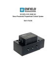
S2-025-U-04 (USB S2)
Servo Pneumatic Proportional Control System
User’s Guide
© 2014 Enfield Technologies
As Enfield Technologies strives for continuous
improvement and dedication to product development,
specifications are subject to change
v20140115
WARNING: Installation and operation of electronic and high pressure
systems (fluids and compressed gas) involves risk including property
damage and personal injury or death. Users should be properly trained
or certified and take safety precautions.
S2-025-U-04
User’s Manual
Page 2 of 25
Table of Contents
Warnings & Notices ...................................................................................................................................... 3 Factory Default Setting ................................................................................................................................. 4 Quick Start Procedure ................................................................................................................................... 5 Wire Feedback .............................................................................................................................................. 5 Wire Command ............................................................................................................................................. 5 Wire Power .................................................................................................................................................. 5 Connect to Valve ........................................................................................................................................... 6 Confirm the feedback signal is working properly ......................................................................................... 7 Confirm the command signal is wired properly ............................................................................................ 9 Connect Pneumatic Lines ............................................................................................................................ 10 Set Cylinder Area Ratio ............................................................................................................................... 11 Tune System ................................................................................................................................................ 12 Advanced Settings ....................................................................................................................................... 17 Save and Load Files ..................................................................................................................................... 20 Troubleshooting .......................................................................................................................................... 24 Maximum Moving Mass .............................................................................................................................. 25 © 2014 Enfield Technologies
As Enfield Technologies strives for continuous
improvement and dedication to product development,
specifications are subject to change
v20140115
WARNING: Installation and operation of electronic and high pressure
systems (fluids and compressed gas) involves risk including property
damage and personal injury or death. Users should be properly trained
or certified and take safety precautions.
S2-025-U-04
User’s Manual
Page 3 of 25
Warnings & Notices
WARNING:
Installation and operation of electric and high pressure systems (fluids and compressed gas) involves risk
including property damage and personal injury or death.
Installers and users should be properly trained or certified and take safety precautions. This product may cause
death, personal injury, or property damage if improperly used or installed.
The information in this document and other information from Enfield Technologies and its authorized
representatives are intended for use by persons having technical expertise in selecting and using these
products. Product owners (“you”) should analyze all technical and safety requirements of your specific
application, including the consequences of any possible failure, before selecting a product. This product may
not be suitable for all applications, such as those acting upon people. Suitability is solely your responsibility.
Because the requirements for each application may vary considerably, you are solely responsible for conducting
any testing or analysis that may be required to determine the suitability of the product for your application, and
to ensure that all performance, safety and warning requirements for your application are met.
Caution:
While the product is low voltage, it contains open-frame electronic components and care should be taken to prevent unintentional contact with the product to avoid damage to person or property.
The S2-025-U-04 is an electro-static sensitive device. Use appropriate electro-static discharge (ESD) procedures during
handling and installation.
Notice:
Use and purchase of this product is subject to Enfield Technologies’ Terms and Conditions of Sale and Use. Improper
installation or use voids warranty. Consult factory regarding special applications. Specifications are subject to change.
Reasonable efforts have been made to provide useful and correct information in this document, but this document may contain
errors and omissions, and it is subject to change.
Contact: Enfield Technologies
50 Waterview Drive
Shelton, CT 06484 USA
+1 203 375 3100
+1 800 504 3334 toll free North America
[email protected]
www.enfieldtech.com
© 2014 Enfield Technologies
As Enfield Technologies strives for continuous
improvement and dedication to product development,
specifications are subject to change
v20140115
WARNING: Installation and operation of electronic and high pressure
systems (fluids and compressed gas) involves risk including property
damage and personal injury or death. Users should be properly trained
or certified and take safety precautions.
S2-025-U-04
User’s Manual
Page 4 of 25
Factory Default Setting
Initial Signals Configuration
Command
Feedback
Invert Feedback Sensor Polarity
Cylinder Configuration
Cylinder Bore
Rode Diameter
Area Ratio
Port Connection
Basic Settings
Proportional Gain
Derivative Gain
Force Damping Gain
Offset
Advanced Settings
Minimum Position
Maximum Position
Ramp Up
Ramp Down
Valve Settings
Factory Default Condition
0-10V
0-10V
Unchecked
Setting
Command input setup for 0-10V
Feedback input setup for 0-10V
Feedback should increase as cylinder is extended
Factory Default Condition
2.000 in
1.000 in
0.8920
Standard
Setting
Cylinder bore size set to 2.000 inches
Cylinder rod size set to 1.000 inch
Area Ratio set to 0.8920
Port 2 connects to back of cylinder and port 4 to front
Factory Default Condition
0%
0%
0%
0%
Setting
Proportional gain set to zero
Derivative gain set to zero
Force Damping gain set to zero
Offset set to zero
Factory Default Condition
0%
100%
0%
0%
Setting
No adjustment to minimum position
No adjustment to maximum position
Command input is not ramped in extend direction
Command input is not ramped in retract direction
Factory Default Condition
Setting
Dead Band
Dither Amplitude
Valve Offset
0%
75%
0%
No deadband elimination is being implemented
Dither amplitude is set at 75% of maximum
Valve’s spool position is not offset in either direction
LED
Factory Default Condition
Setting
Power LED
Status LED
Red
Green
Power is on
Offset ≈ 0 (RP4 is centered)
© 2014 Enfield Technologies
As Enfield Technologies strives for continuous
improvement and dedication to product development,
specifications are subject to change
v20140115
WARNING: Installation and operation of electronic and high pressure
systems (fluids and compressed gas) involves risk including property
damage and personal injury or death. Users should be properly trained
or certified and take safety precautions.
S2-025-U-04
User’s Manual
Page 5 of 25
Quick Start Procedure
To Actuator
To Actuator
Port 4
Port 2
(Bn)24V dc Power
(Bu) DC Common
(Bk) Command
(Wh) Feedback
(Gy)+10V Excitation
1.
Port 5
Port 1
Port 3
Exhaust
Inlet Pressure
Exhaust
Wire Feedback
a.
Resistive Feedback Devices - For Resistive Feedback devices: the grey wire of the S2-025-U-04, +10V,
should be connected to the high side of the resistor, the blue wire, ground, should be connected to the low
side of the resistor, and the white wire, feedback, should be connected to the output. Ensure proper
polarity with a +10V output corresponding to the fully extended position and a 0V output corresponding to
the fully retracted cylinder positions.
b.
Powered Feedback Devices - when using a powered feedback sensor, use manufacturer’s requirements for
powering the sensor. The output of the sensor should be connected to the white wire, feedback, of the S2025-U-04. For 4…20mA feedback signals, ensure that the low side is connected to ground, the blue wire
of the S2-025-U-04. For 0…10Vdc sensors, ensure proper polarity with a +10V output corresponding to the
fully extended position and a 0V output corresponding to the fully retracted cylinder positions. For 4…20mA
sensors, ensure proper polarity with a 20mA output corresponding to the fully extended position and a 4mA
output corresponding to the fully retracted cylinder positions
Note: The input impedance for 0…10Vdc inputs is 100kΩ while the input impedance for 4…20mA signals is
210Ω
2.
Wire Command
a. “Command +” (0…10V or 4…20m input) should be connected to the black wire of the S2-025-U-04 and
“Command –“ (0V) should be connected to the blue wire of the S2-025-U-04.
3.
Wire Power
a. “Power +” (+12 or +24V) should be connected to the brown wire of the S2-025-U-04 and “Power –“ (0V)
should be applied to the blue wire.
© 2014 Enfield Technologies
As Enfield Technologies strives for continuous
improvement and dedication to product development,
specifications are subject to change
v20140115
WARNING: Installation and operation of electronic and high pressure
systems (fluids and compressed gas) involves risk including property
damage and personal injury or death. Users should be properly trained
or certified and take safety precautions.
S2-025-U-04
User’s Manual
Page 6 of 25
4.
Connect to Valve
a.
Connect Enfield Technologies’’ USB cable, A-CBL-SAUB-0405P-MM-XXXX, or equivalent from the computer
to the S2-025-U-04 valve.
b.
c.
d.
Launch the S2-025-U-04 Configuration Interface.
Click on the Initial Setup Tab
In the Communication section, shown in the red box below, select the COM port associated with the valve
from the Select Port drop down.
e.
Once the COM port has been selected, click the “Enable Communication” checkbox.
© 2014 Enfield Technologies
As Enfield Technologies strives for continuous
improvement and dedication to product development,
specifications are subject to change
v20140115
WARNING: Installation and operation of electronic and high pressure
systems (fluids and compressed gas) involves risk including property
damage and personal injury or death. Users should be properly trained
or certified and take safety precautions.
S2-025-U-04
User’s Manual
Page 7 of 25
5.
f.
The valve should now be connected. Valve serial number and software version will now be displayed.
g.
If you are unable to connect to the S2-025-U-04 try the following:
i. Unplug and replug the USB cable to see if a COM port populates.
ii. Make sure S2-025-U-04 has power.
iii. Cycle the power to the S2-025-U-04
iv. Refer to Drivers Manual found at http://enfieldtech.com/products/positioning-system/
Confirm the Feedback Signal is Working Properly
a.
Click on the Initial Setup Tab
b.
In the input signals configuration, shown in the red box below, select whether the feedback input is
4…20mA or 0…10V
c.
Click on the Basic Settings Tab
© 2014 Enfield Technologies
As Enfield Technologies strives for continuous
improvement and dedication to product development,
specifications are subject to change
v20140115
WARNING: Installation and operation of electronic and high pressure
systems (fluids and compressed gas) involves risk including property
damage and personal injury or death. Users should be properly trained
or certified and take safety precautions.
S2-025-U-04
User’s Manual
Page 8 of 25
d.
The position of the cylinder will be shown on the Cylinder Feedback slider
e.
Move the cylinder by hand and confirm that the valve is receiving the feedback signal. The Cylinder
Feedback slider should proportionally increase from 0…100% as the cylinder is extended.
f.
If the Cylinder Feedback slider decreases from 100% to 0% as the cylinder is extended, the polarity of the
feedback sensor is transposed. To correct this, click the “Invert Feedback Sensor Polarity” checkbox, shown
in the red box below
© 2014 Enfield Technologies
As Enfield Technologies strives for continuous
improvement and dedication to product development,
specifications are subject to change
v20140115
WARNING: Installation and operation of electronic and high pressure
systems (fluids and compressed gas) involves risk including property
damage and personal injury or death. Users should be properly trained
or certified and take safety precautions.
S2-025-U-04
User’s Manual
Page 9 of 25
6.
Confirm the Command Signal is Wired Properly
a.
Click on the Initial Setup Tab
b.
In the input signals configuration, shown in the red box below, select whether the command input is
4…20mA or 0…10V
c.
Click on the Basic Settings Tab
d.
The command signal from the PLC analog output or other analog input source will be shown on the Cylinder
Command slider
e.
Vary this output to confirm that the valve is receiving the command signal. The Cylinder Command slider
should move from 0…100% as the command from the PLC is increased from 0…10V or 4…20mA.
© 2014 Enfield Technologies
As Enfield Technologies strives for continuous
improvement and dedication to product development,
specifications are subject to change
v20140115
WARNING: Installation and operation of electronic and high pressure
systems (fluids and compressed gas) involves risk including property
damage and personal injury or death. Users should be properly trained
or certified and take safety precautions.
S2-025-U-04
User’s Manual
Page 10 of 25
7.
Connect Pneumatic Lines
a. Connect port 2 of the valve to the back of the cylinder and port 4 to the front as shown below. It is
recommended that the valve be placed as close as possible to the cylinder. To minimize pressure drop out
of the valve ¼” NPTF to 3/8 OD straight fittings are recommended.
b.
If it desirable to connect port 4 of the valve to the back of the cylinder and port 2 to the front, go to the
initial setup tab and select the “Transposed” checkbox in the Port Connection area, shown in the red box
below.
c.
Inlet air should be dry (-40C dew point) non-lubricated air, non-flammable & non-corrosive dry gases (0.3
micron fine grade coalescing filter with 5 micron pre-filter) at 0-150psig (80-120 typical with minimal
pressure fluctuation).
d.
Once air filtration specification has been confirmed, connect inlet air to port 1
© 2014 Enfield Technologies
As Enfield Technologies strives for continuous
improvement and dedication to product development,
specifications are subject to change
v20140115
WARNING: Installation and operation of electronic and high pressure
systems (fluids and compressed gas) involves risk including property
damage and personal injury or death. Users should be properly trained
or certified and take safety precautions.
S2-025-U-04
User’s Manual
Page 11 of 25
8.
Set Cylinder Area Ratio
a.
Click on the Initial Setup tab
b.
In the Cylinder Configuration section, shown in the red box below, enter the diameter in inches of the
cylinder bore and rod diameter.
c.
Once entered, the Area ratio will be calculated automatically.
© 2014 Enfield Technologies
As Enfield Technologies strives for continuous
improvement and dedication to product development,
specifications are subject to change
v20140115
WARNING: Installation and operation of electronic and high pressure
systems (fluids and compressed gas) involves risk including property
damage and personal injury or death. Users should be properly trained
or certified and take safety precautions.
S2-025-U-04
User’s Manual
Page 12 of 25
9.
Tune System
a. Restore to factory default settings by clicking the box highlighted in red below.
b.
Turn on air to the system
c.
Select the PC Square wave check box from the Command Source selection, shown, show in the red box
below.
d.
This will provide a text command signal that alternates between the two positions set by the Minimum and
Maximum sliders, shown in the red box below. The Period slider will determine the amount of time for each
cycle. To begin testing, use a signal such as 25% Minimum, 75% maximum and 4.00 Second for Period.
© 2014 Enfield Technologies
As Enfield Technologies strives for continuous
improvement and dedication to product development,
specifications are subject to change
v20140115
WARNING: Installation and operation of electronic and high pressure
systems (fluids and compressed gas) involves risk including property
damage and personal injury or death. Users should be properly trained
or certified and take safety precautions.
S2-025-U-04
User’s Manual
Page 13 of 25
e.
Increase the Proportional slider slowly (1% increments). The system should begin to move. If the system is
not responding or is stuck in the fully extended or retracted position check tubing and feedback sensor
polarity.
© 2014 Enfield Technologies
As Enfield Technologies strives for continuous
improvement and dedication to product development,
specifications are subject to change
v20140115
WARNING: Installation and operation of electronic and high pressure
systems (fluids and compressed gas) involves risk including property
damage and personal injury or death. Users should be properly trained
or certified and take safety precautions.
S2-025-U-04
User’s Manual
Page 14 of 25
f.
Continue increasing the Proportional Slider until the Cylinder Feedback slider begins to follow the Cylinder
Command Slider.
g.
If the system begins to oscillate or overshot, increase the Force Damping slider until the oscillation or
overshoot has been removed.
h.
Repeat the two previous steps as necessary, until the system exhibits the desired dynamics.
© 2014 Enfield Technologies
As Enfield Technologies strives for continuous
improvement and dedication to product development,
specifications are subject to change
v20140115
WARNING: Installation and operation of electronic and high pressure
systems (fluids and compressed gas) involves risk including property
damage and personal injury or death. Users should be properly trained
or certified and take safety precautions.
S2-025-U-04
User’s Manual
Page 15 of 25
i.
To optimize system performance, slowly decrease the Force Damping slider and increase the Derivative
slider until optimum system performance is reached.
j.
If an offset is noticed between the Cylinder Command and Cylinder Feedback sliders, the Offset slider can
be adjusted to compensate. This is most likely the case in vertical applications. Assuming no mechanical
linkages reversing direction of motion: for cylinder with rods facing up, increase the offset and for cylinders
with rods facing down decrease the offset.
© 2014 Enfield Technologies
As Enfield Technologies strives for continuous
improvement and dedication to product development,
specifications are subject to change
v20140115
WARNING: Installation and operation of electronic and high pressure
systems (fluids and compressed gas) involves risk including property
damage and personal injury or death. Users should be properly trained
or certified and take safety precautions.
S2-025-U-04
User’s Manual
Page 16 of 25
k.
Select the Analog Input checkbox, shown in the red box below, to switch the command back to your
external input.
l.
Confirm that the system is responding to your analog input signal. You will be able to see the Cylinder
Command slider moving in unison with your command signal. If this does not happen, confirm your
command source and wiring.
© 2014 Enfield Technologies
As Enfield Technologies strives for continuous
improvement and dedication to product development,
specifications are subject to change
v20140115
WARNING: Installation and operation of electronic and high pressure
systems (fluids and compressed gas) involves risk including property
damage and personal injury or death. Users should be properly trained
or certified and take safety precautions.
S2-025-U-04
User’s Manual
Page 17 of 25
Advanced Settings
1.
Minimum and Maximum Position – In many cases, the length of a feedback sensor may be longer than the length of
the cylinder travel. In these cases, the minimum and maximum position sliders, shown in the red box below, can be
adjusted so the feedback seen by the S2-025-U-04, is a linear 0…10V or 4…20mA along the cylinder’s full travel.
Example: If a 9” stroke cylinder was placed in the middle of a 10” stroke feedback sensor, the feedback would move
from 5% to 95% as the cylinder moved along its full travel. If the minimum and maximum position sliders were set at
5% and 95% respectively, the Cylinder Feedback slider would now read 0…100% along the full travel of the cylinder.
© 2014 Enfield Technologies
As Enfield Technologies strives for continuous
improvement and dedication to product development,
specifications are subject to change
v20140115
WARNING: Installation and operation of electronic and high pressure
systems (fluids and compressed gas) involves risk including property
damage and personal injury or death. Users should be properly trained
or certified and take safety precautions.
S2-025-U-04
User’s Manual
Page 18 of 25
2.
Ramp Up and Ramp Down – The ramp up and ramp down sliders, shown in the red box below, can be used to set the
maximum velocity in the extend and retract directions.
By increasing the ramp up, the velocity of the cylinder in the extend direction will be decreased. By increasing the
ramp down, the velocity in the retract direction will be decreased
Effect of Increasing Ramp Up
© 2014 Enfield Technologies
As Enfield Technologies strives for continuous
improvement and dedication to product development,
specifications are subject to change
v20140115
Effect of Increasing Ramp Down
WARNING: Installation and operation of electronic and high pressure
systems (fluids and compressed gas) involves risk including property
damage and personal injury or death. Users should be properly trained
or certified and take safety precautions.
S2-025-U-04
User’s Manual
Page 19 of 25
3.
Valve Settings – The valve settings, Dead Band, Dither Amplitude and Valve Offset, shown in the red box below, adjust
the underlying valve characteristics of the S2-025-U-04. For the majority of applications, these settings will not be
adjusted from their factory default settings.
Dead Band – Adjusts the effective overlap of the valve. By increasing the Dead Band slider, the valve will begin to
open sooner.
Dither Amplitude – In order to keep the valve responding quickly, there is a constant high frequency dither signal
provided to the valve to keep the spool in dynamic friction as opposed to static friction. The Dither Amplitude slider
adjusts the amplitude of this signal.
Valve Offset – This adjustment provides a constant offset to the position of the spool. The spool can be offset in either
direction by adjusting the Valve Offset slider.
© 2014 Enfield Technologies
As Enfield Technologies strives for continuous
improvement and dedication to product development,
specifications are subject to change
v20140115
WARNING: Installation and operation of electronic and high pressure
systems (fluids and compressed gas) involves risk including property
damage and personal injury or death. Users should be properly trained
or certified and take safety precautions.
S2-025-U-04
User’s Manual
Page 20 of 25
Save and Load Configuration Files
1.
Saving a File
a. Click the “Save Configuration File” button, shown in the red box below, to save the current configuration as
a .txt file.
b.
A window will then open allowing the file to be named and the save location selected.
© 2014 Enfield Technologies
As Enfield Technologies strives for continuous
improvement and dedication to product development,
specifications are subject to change
v20140115
WARNING: Installation and operation of electronic and high pressure
systems (fluids and compressed gas) involves risk including property
damage and personal injury or death. Users should be properly trained
or certified and take safety precautions.
S2-025-U-04
User’s Manual
Page 21 of 25
2.
Loading a file
a.
Once a file has been saved, it can be opened at any time by clicking the “Load Configuration File” button.
b.
If a valve is currently connected, a message will then appear warning that loading a configuration file will
overwrite any of the current settings that have not been saved. Click “OK” to continue.
© 2014 Enfield Technologies
As Enfield Technologies strives for continuous
improvement and dedication to product development,
specifications are subject to change
v20140115
WARNING: Installation and operation of electronic and high pressure
systems (fluids and compressed gas) involves risk including property
damage and personal injury or death. Users should be properly trained
or certified and take safety precautions.
S2-025-U-04
User’s Manual
Page 22 of 25
c.
A browser will then open allowing selection of the saved configuration file.
d.
Once loaded, if the valve is disconnected, the window will act as a viewer, displaying the settings from the
loaded file.
© 2014 Enfield Technologies
As Enfield Technologies strives for continuous
improvement and dedication to product development,
specifications are subject to change
v20140115
WARNING: Installation and operation of electronic and high pressure
systems (fluids and compressed gas) involves risk including property
damage and personal injury or death. Users should be properly trained
or certified and take safety precautions.
S2-025-U-04
User’s Manual
Page 23 of 25
e.
If the valve is connected, the setting will immediately be saved to the RAM of the S2-025-U-04. To check if
the valve is connected, go to the “Initial Setup” tab and look under Communication section to see that the
word “Connected” is present.
f.
In order to save the newly loaded settings to the valve, click the “Save Configuration to S2” button.
© 2014 Enfield Technologies
As Enfield Technologies strives for continuous
improvement and dedication to product development,
specifications are subject to change
v20140115
WARNING: Installation and operation of electronic and high pressure
systems (fluids and compressed gas) involves risk including property
damage and personal injury or death. Users should be properly trained
or certified and take safety precautions.
S2-025-U-04
User’s Manual
Page 24 of 25
10. Troubleshooting
a. Check to see if probable cause and corrective action is listed in the table below
Symptom
Probable Causes
Corrective Action
System Totally Unresponsive
Power Not Applied
Apply power, check all power wiring
Air Off
Proportional Gain too Low
Signal Wiring
Turn air on
Increase the Proportional Slider
Verify signal wiring for command and feedback; also verify
mechanical system polarity
Verify all Wiring
Proportional Gain too Low
Increase the Proportional Slider
Force Damping Gain too High
Decrease Force Damping Slider
Power Supply Voltage not Stable
Check power wiring; change power supply
Inverted Polarity
System Mildly Responsive or
Sluggish
Cylinder too Small
System ‘Pegs’ or ‘Rails’
System Fails to Converge or is
Inaccurate
No Feedback Signal
Decrease moving mass, increase cylinder size, or increase
inlet pressure.
Connect Feedback Signal
Feedback Connected Improperly
Verify all wiring is as shown in application examples and as
described in the “Wire Feedback” section of this document
Cylinder Connected Improperly
Verify Polarity of Cylinder as shown in “Connect Pneumatic
Lines”
Incorrect Wiring
Verify all wiring is as shown in application examples and as
described in the “Installation” section of this document
Proportional Gain too low
Force Damping too high
Insure mechanical system is free from binding and high
friction.
Increase the Proportional Slider
Decrease Force Damping Slider
Offset Gain adjusted incorrectly
Adjust the offset slider
Wrong Area Ratio
Check the “Cylinder Bore” and “Rod Diameter” settings
Air Leaks
Insure there are no air leaks in the system
Insure that inlet air meets valve specifications. See
“Connect Pneumatic Lines”
Decrease Proportional gain slider
Increase Force Damping slider
Decrease Derivative gain slider
Mechanical System
S2-025-U-04 Sticking
System Oscillates
Proportional Gain too high
Not Enough Force Damping
Derivative Gain too high
System ‘Buzzes’
Input Signal Noise (possibly 60Hz)
Verify that large or high power machinery is not operating
nearby. Also, verify input signal integrity by examining the
signal with an oscilloscope.
Input Signals not connected
Verify all wiring as shown in the “Wire Command” and “Wire
Feedback” sections of this document
b.
DC Common not connected
Contact Enfield Technologies for additional help
© 2014 Enfield Technologies
As Enfield Technologies strives for continuous
improvement and dedication to product development,
specifications are subject to change
v20140115
Verify all DC common connections
WARNING: Installation and operation of electronic and high pressure
systems (fluids and compressed gas) involves risk including property
damage and personal injury or death. Users should be properly trained
or certified and take safety precautions.
S2-025-U-04
User’s Manual
Page 25 of 25
Maximum Moving Mass
The table below recommends the maximum moving mass for a cylinder controlled by a S2-025-U-04 for horizontal and vertical
applications. It should be noted that the maximum moving mass recommended is lower than the cylinders maximum output
force. This is intentional so the cylinder has enough available force to quickly accelerate and decelerate the moving mass under
control, more force than it requires to simply begin movement. Sizing the cylinder too small can result in an unstable system
that is difficult, if not impossible, to control. Actual mass will vary based on cylinder speed and mechanical assembly (e.g.
friction in cylinder or system, air pressure, etc.)
For retrofitting systems already in place, it may not be possible to change cylinder size, resulting in an undersized cylinder
compared to the moving mass. For these situations, consider adding flow controls to reduce the velocity and the resulting
kinetic energy of the system. Energy equation: mv
Fd 0 [With lower velocity, a lower force is required to stop the
moving mass].
Example 1
Cylinder
Cylinder Bore Size
Maximum Weight (Pounds)
(Inches)
Horizontal
Vertical
1-1/16
55
15
1-1/4
75
20
1-1/2
110
25
1-3/4
150
35
2
200
50
2-1/2
240
80
3
330
110
4
400
200
5
500
310
6
800
450
8
1200
800
Cylinders larger than 8” may be used
Cylinder
Moving Mass
Moving Mass
Example 3
Moving Mass
Example 2
Cylinder
4x
Moving Mass
Cylinder
Cylinder
Example 4
4x
200 lb. moving mass
Moving Mass
Example 1: Vertical Setups – 4” bore
Example 2: Horizontal Setup – 2” bore
Example 3: Horizontal Lever Arm Setup – 6” bore
Example 4: Vertical Force Multiplier Setup – 8” bore
Warranty: This product is covered by a 1 year Enfield Technologies limited warranty. Contact Enfield Technologies or visit website for more details.
Notice: Use and purchase of this product is subject to Enfield Technologies’ Terms and Conditions of Sale and Use. Improper installation or use voids warranty. This product may not be
suitable for all applications, such as those acting upon people, and suitability is solely the buyer’s responsibility. Consult factory regarding special applications.
© 2014 Enfield Technologies
As Enfield Technologies strives for continuous
improvement and dedication to product development,
specifications are subject to change
v20140115
WARNING: Installation and operation of electronic and high pressure
systems (fluids and compressed gas) involves risk including property
damage and personal injury or death. Users should be properly trained
or certified and take safety precautions.


