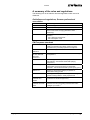
1
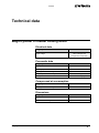
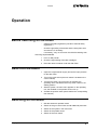
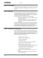
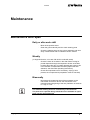
En
Operating instructions and spare parts list
MagicCylinder II
Powder coating booth
V 03/08
Documentation -
Powder coating booth MagicCylinder II
© Copyright 2007 ITW Gema GmbH
All rights reserved.
This publication is protected by copyright. Unauthorized copying is
prohibited by law. No part of this publication may be reproduced,
photocopied, translated, stored on a retrieval system or transmitted in
any form or by any means for any purpose, neither as a whole nor
partially, without the express written consent of ITW Gema GmbH.
OptiTronic, OptiGun, EasyTronic, EasySelect, EasyFlow and
SuperCorona are registered trademarks of ITW Gema GmbH.
OptiMatic, OptiMove, OptiMaster, OptiPlus, MultiTronic and Gematic are
trademarks of ITW Gema GmbH.
All other product names are trademarks or registered trademarks of their
respective holders.
Reference is made in this manual to different trademarks or registered
trademarks. Such references do not mean that the manufacturers
concerned approve of or are bound in any form by this manual. We have
endeavored to retain the preferred spelling of the trademarks, and
registered trademarks of the copyright holders.
To the best of our knowledge and belief, the information contained in this
publication was correct and valid on the date of issue. ITW Gema GmbH
makes no representations or warranties with respect to the contents or
use of this publication, and reserves the right to revise this publication
and make changes to its content without prior notice.
Printed in Switzerland
ITW Gema GmbH
Mövenstrasse 17
9015 St. Gallen
Switzerland
Phone: +41-71-313 83 00
Fax.: +41-71-313 83 83
E-Mail: [email protected]
Homepage: www.itwgema.ch
V 03/08
Table of contents
General safety regulations
3
Safety symbols (pictograms)...................................................................................3
Conformity of use ....................................................................................................3
Technical safety regulations for stationary electrostatic powder spraying
equipment ...............................................................................................................4
General information ...................................................................................4
Safety conscious working ..........................................................................5
Individual safety regulations for the operating firm and/or operating
personnel ...................................................................................................6
Notes on special types of hazard...............................................................6
Safety requirements for electrostatic powder coating................................8
A summary of the rules and regulations ....................................................9
Product specific security measures ......................................................................10
Installation ................................................................................................10
Grounding ................................................................................................10
Operating the equipment .........................................................................10
Inspection check ......................................................................................11
Entering the booth....................................................................................11
Repairs.....................................................................................................11
About this manual
13
General information ..............................................................................................13
Structure and function
15
Field of application ................................................................................................15
Function description..............................................................................................15
Operational procedure .............................................................................16
Powder flow..............................................................................................17
Booth - superstructure ..........................................................................................18
Booth - basement..................................................................................................18
Floor blow-off system...............................................................................19
Powder suction ........................................................................................20
Exhaust air system with After Filter.......................................................................20
Fire protection .......................................................................................................21
Cleaning operation mode......................................................................................21
Automatic booth cleaning.........................................................................21
Powder recovery ...................................................................................................21
Automatic guns .....................................................................................................22
Cleaning the guns .................................................................................................22
Technical data
25
MagicCylinder II Powder coating booth ................................................................25
Electrical data ..........................................................................................25
Pneumatic data ........................................................................................25
Compressed air consumption ..................................................................25
Dimensions ..............................................................................................25
MagicCylinder II
Table of contents • 1
V 03/08
Start-up
27
Set-up and assembly............................................................................................ 27
Installation ............................................................................................... 27
Cable connections / junctions............................................................................... 27
Grounding ................................................................................................ 27
Operation
29
Before switching on the booth .............................................................................. 29
Switch on the booth .............................................................................................. 29
Switching off the booth ......................................................................................... 29
Alarm messages................................................................................................... 30
Filter cleaning ....................................................................................................... 30
Color change and cleaning................................................................................... 30
Maintenance
33
Maintenance and repair........................................................................................ 33
Daily or after each shift............................................................................ 33
Weekly ..................................................................................................... 33
Biannually ................................................................................................ 33
Maintenance and repair of the cyclone separator ................................................ 34
Maintenance and repair of the sieve machine...................................................... 34
Maintenance of the After Filter pressure gauges (filter and ventilator) ................ 34
Replacing spare parts........................................................................................... 34
Functional check................................................................................................... 35
General information ................................................................................. 35
Procedure of the function check.............................................................. 35
Troubleshooting
37
General information .............................................................................................. 37
Problem fixing ....................................................................................................... 37
Setting values ....................................................................................................... 39
Spare parts list
41
Ordering spare parts............................................................................................. 41
MagicCylinder II - spare parts list ......................................................................... 42
MagicCylinder II - Flap drive unit .......................................................................... 44
MagicCylinder II - Pressure tank for the floor blow-off system............................. 46
MagicCylinder II - Pressure tank for the ring blow-off system.............................. 48
MagicCylinder II - gun blow off equipment ........................................................... 50
MagicCylinder II - door drive unit.......................................................................... 52
MagicCylinder II - fan control................................................................................ 54
2 • Table of contents
MagicCylinder II
V 03/08
General safety regulations
This chapter sets out the fundamental safety regulations that must be
followed by the user and third parties using the MagicCylinder II powder
coating booth.
These safety regulations must be read and understood before the
MagicCylinder II powder coating booth is put into operation.
Safety symbols (pictograms)
The following warnings with their meanings can be found in the ITW
Gema operating instructions. The general safety precautions must also
be followed as well as the regulations in the operating instructions.
DANGER!
danger due to live electricity or moving parts. Possible consequences:
Death or serious injury
WARNING!
Improper use of the equipment could damage the machine or cause it to
malfunction. Possible consequences: minor injuries or damage to
equipment
INFORMATION!
useful tips and other information
Conformity of use
1. The MagicCylinder II powder coating booth is built to the latest
specification and conforms to the recognized technical safety
regulations and is designed for the normal application of powder
coating.
2. Any other use is considered as non-conform. The manufacturer
is not responsible for any damage resulting from this - the risk for
this is assumed by the user alone! If the MagicCylinder II powder
coating booth is to be used for other purposes or other
substances outside of our guidelines then ITW Gema GmbH
should be consulted.
MagicCylinder II
General safety regulations • 3
V 03/08
3. Observance of the operating, service and maintenance
instructions specified by the manufacturer is also part of
conformity of use. The MagicCylinder II powder coating booth
should only be used, maintained and started up by trained
personnel, who are informed about and are familiar with the
possible hazards involved.
4. Start-up (i.e. the execution of a particular operation) is forbidden
until it has been established that the MagicCylinder II powder
coating booth has been set up and wired according to the
guidelines for machinery (98/37 EG). EN 60204-1 (machine
safety) must also be observed.
5. Unauthorized modifications to MagicCylinder II powder coating
booth exempts the manufacturer from any liability from resulting
damage.
6. The relevant accident prevention regulations, as well as other
generally recognized safety regulations, occupational health and
structural regulations are to be observed.
7. Furthermore, the country-specific safety regulations also must be
observed.
Explosion protection
II 3 D
Protection type
Temperature class
IP54
T6 (zone 21)
T4 (zone 22)
Technical safety regulations for stationary
electrostatic powder spraying equipment
General information
Stationary ITW Gema GmbH electrostatic spraying equipment is built to
the "state of the art" and is operationally safe. This equipment can be
dangerous if it is not used for its specified purpose. Consequently it
should be noted that there exists a danger to life and limb of the user or
third party, a danger of damage to the equipment and other machinery
belonging to the user and a hazard to the efficient operation of the
equipment.
1. The powder spraying equipment should only be started up and
used once the operating instructions have been carefully studied.
Incorrect operation of the control unit can lead to accidents,
malfunctions or damage to the control itself or to the plant.
2. Before every start-up check the equipment for operational safety
(regular servicing is essential)!
3. Safety regulations BGI 764 and VDE regulations DIN VDE 0147,
Part 1, must be observed for safe operation.
4. Please observe the local safety regulations!
5. Disconnect the plugs before the machines are opened for repair.
6. The plug connections between the powder spraying equipment
and the mains should only be removed when the power supply is
switched off.
4 • General safety regulations
MagicCylinder II
V 03/08
7. The connecting cables between the control unit and the spray
gun must be installed in such a way, that they cannot be
damaged during the operation. Please observe the local safety
regulations!
8. Only original ITW Gema spare parts should be used, because
the explosion protection will also be preserved that way. Damage
caused by other parts is not covered by guarantee.
9. If ITW Gema GmbH powder spraying equipment is used in
conjunction with machinery from other manufacturers, then their
safety regulations must also be taken into account.
10. Before starting work familiarize yourself with all installations and
operating elements, as well as with their functions!
Familiarization during operation is too late!
11. Caution must be exercised when working with a powder/air
mixture! A powder/air mixture in the right concentration is
flammable! Smoking is forbidden in the entire plant area!
12. As a general rule for all powder spraying installations, persons
with pacemakers should never enter high voltage areas or areas
with electromagnetic fields. Persons with pacemakers should not
enter areas with powder spraying installations!
WARNING!
We point out that the customer himself is responsible for the safe
operation of the equipment. ITW Gema GmbH is in no way
responsible for any resulting damage!
Safety conscious working
Each person responsible for the assembly, start-up, operation, service
and repair of powder spraying equipment must have read and
understood the operating instructions and the "Safety regulations"
chapter. The operator must ensure that the user has had the appropriate
training for powder spraying equipment and is aware of the possible
sources of danger.
The control units for the spray guns must be installed and used in zone
22. Spray guns are allowed in zone 21.
The powder spraying equipment should only be used by trained and
authorized personnel. This applies to modifications to the electrical
equipment, which should only be carried out by a specialist.
The operating instructions and the necessary closing down procedures
must be followed before any work is carried out concerning the set-up,
start-up, operation, modification, operating conditions, mode of operation,
servicing, inspection or repairs.
The powder spray equipment can be turned off by using the main switch
or failing that, the emergency shut-down. Individual components can be
turned off during operation by using the appropriate switches.
MagicCylinder II
General safety regulations • 5
V 03/08
Individual safety regulations for the operating
firm and/or operating personnel
1. Any operating method, which will negatively influence the
technical safety of the powder spraying equipment, is to be
avoided.
2. The operator should care about no non-authorized personnel
works on the powder spraying equipment (e.g. this also includes
using the equipment for non-conform work).
3. For dangerous materials, the employer has to provide an
operating instructions manual for specifying the dangers arising
for humans and environment by handling dangerous materials,
as well as the necessary preventive measures and behavior
rules. The operating instructions manual has to be written in an
understandable form and in the language of the persons
employed, and has to be announced in a suitable place in the
working area.
4. The operator is under obligation to check the powder spraying
equipment at least once every shift for signs of external damage,
defects or changes (including the operating characteristics) which
could influence safety and to report them immediately.
5. The operator is obliged to check that the powder spraying
equipment is only operated when in satisfactory condition.
6. As far as it is necessary, the operating firm must ensure that the
operating personnel wear protective clothing (e.g. facemasks).
7. The operating firm must guarantee cleanliness and an overview
of the workplace with suitable instructions and checks in and
around the powder spraying equipment.
8. No safety devices should be dismantled or put out of operation. If
the dismantling of a safety device for set-up, repair or servicing is
necessary, reassembly of the safety devices must take place
immediately after the maintenance or repair work is finished. All
maintenance activities must take place when the powder
spraying equipment is switched off. The operator must train and
commit the responsible personnel to this.
9. Activities, such as checking powder fluidization or checking the
high voltage spray gun etc., must be carried out with the powder
spraying equipment switched on.
Notes on special types of hazard
Power/tension
It is necessary to refer once more to the danger of life from high voltage
current if the shutdown procedures are not observed. High voltage
equipment must not be opened - the plug must first be taken out otherwise there is danger of electric shock.
Powder
Powder/air mixtures can be ignited by sparks. There must be sufficient
ventilation in the powder coating booth. Powder lying on the floor around
the powder spraying equipment is a potentially dangerous source of
slipping.
6 • General safety regulations
MagicCylinder II
V 03/08
Static charges
Static charges can have the following consequences: Charges to people,
electric shocks, sparking. Charging of objects must be avoided - see
chapter "Earthing".
Grounding
All electricity conducting parts and machinery found in the workplace
(according to DIN VDE 0745, part 102: 1,5 meters either side and 2,5
meters around each booth opening) have to be grounded. The earthing
resistance of each object must amount to maximally 1 MOhm. The
resistance must be tested regularly. The condition of the work piece
attachments, as well as the hangers, must guarantee that the work
pieces remain grounded. If the earthing of the machinery includes the
suspension arrangements, then these must constantly be kept clean in
order to guarantee the necessary conductivity. The appropriate
measuring devices must be kept ready in the workplace, in order to
check the grounding.
Compressed air
When there are longer pauses or stand-still times between working, the
powder spraying equipment should be drained of compressed air. There
is a danger of injury when pneumatic hoses are damaged and from the
uncontrolled release and improper use of compressed air.
Crushing and cutting
During operation, moving parts may automatically start to move in the
operating area. It must be ensured that only instructed and trained
personnel go near these parts. The operator should ensure that barriers
comply with the local security regulations.
Access under exceptional circumstances
The operating firm must ensure that local conditions are met when
repairs are made to the electronic parts or when the equipment is
restarted so that there are additional measures such as barriers to
prevent unauthorized access.
Prohibition of unauthorized conversions and
modifications to machines
All unauthorized conversions and modifications to the electrostatic
spraying equipment are forbidden for safety reasons.
The powder spraying equipment should not be used if damaged, the
faulty part must be immediately replaced or repaired. Only original ITW
Gema spare parts may be used! Damage caused by other parts is not
covered by guarantee.
Repairs must only be carried out by specialists or by authorized ITW
Gema service centers. Unauthorized conversions and modifications can
lead to injuries and damage to the equipment. The ITW Gema GmbH
guarantee would no longer be valid.
MagicCylinder II
General safety regulations • 7
V 03/08
Safety requirements for electrostatic powder
coating
1. This equipment is dangerous if the instructions in this operating
manual are not followed.
2. All electrostatic conductive parts, in particular the machinery
within 5 meters of the coating equipment, must be earthed.
3. The floor of the coating area must conduct electricity (normal
concrete is generally conductive).
4. The operating personnel must wear electrically conductive
footwear (e.g. leather soles).
5. The operating personnel should hold the gun with bare hands. If
gloves are worn, these must also conduct electricity.
6. The supplied grounding cable (green/yellow) must be connected
to the grounding screw of the electrostatic manual powder
coating equipment. The grounding cable must have a good
metallic connection with the coating booth, the recovery unit and
the conveyor chain, respectively with the suspension
arrangement of the objects.
7. The electricity and powder supply to the hand guns must be set
up so that they are fully protected against heat and chemical
damage.
8. The powder coating equipment may be able to be switched on
only if the booth is in operation. If the booth stops, the powder
coating device must switch off too.
9. The earthing of all electricity conducting devices (e.g. hooks,
conveyor chains) must be checked on a weekly basis. The
earthing resistance must amount to maximally 1 MOhm.
10. The control device must be switched off if the hand gun is
cleaned or the nozzle is changed.
11. When working with cleaning agents there may be a risk of
hazardous fumes. The manufacturers instructions must be
observed when using such cleaning agents.
12. The manufacturers instructions and the applicable environmental
requirements must be observed when disposing of powder
lacquer and cleaning agents.
13. If any part of the spray gun is damaged (broken parts, fractures)
or missing then it should not be used.
14. For your own safety, only use accessories and attachments listed
in the operating instructions. The use of other parts can lead to
risk of injury. Only original ITW Gema spare parts should be
used!
15. Repairs must only be carried out by specialists and under no
circumstances should they be carried out in the operating area.
The former protection must not be reduced.
16. Conditions leading to dangerous levels of dust concentration in
the powder spraying booths or in the powder spraying areas
must be avoided. There must be sufficient technical ventilation
available, to prevent a dust concentration of more than 50% of
the lower explosion limit (UEG = max. permissible powder/air
concentration). If the UEG is not known, then a value of 10 g/m³
should be considered.
8 • General safety regulations
MagicCylinder II
V 03/08
A summary of the rules and regulations
The following is a list of relevant rules and regulations which are to be
observed:
Guidelines and regulations, German professional
association
BGV A1
General regulations
BGV A2
Electrical equipment and material
BGI 764
Electrostatic coating
BGR 132
Guidelines for the avoidance of the dangers of ignition
due to electrostatic charging (Guideline “Static
Electricity”)
VDMA 24371
Guidelines for electrostatic coating with synthetic
powder1)
- Part 1 General requirements
- Part 2 Examples of use
EN European standards
MagicCylinder II
RL94/9/EC
The approximation of the laws of the Member States
relating to apparatus and safety systems for their
intended use in potentially explosive atmospheres
EN 292-1
EN 292-2
Machine safety 2)
EN 50 014 to EN
50 020, identical:
DIN VDE
0170/0171
Electrical equipment for locations where there is danger
of explosion 3)
EN 50 050
Electrical apparatus for potentially explosive
atmospheres - Electrostatic hand-held spraying
equipment 2)
EN 50 053, part 2
Requirements for the selection, installation and use of
electrostatic spraying equipment for flammable
materials - Hand-held electrostatic powder spray guns 2)
EN 50 177
Stationary electrostatic spraying equipment for
flammable coating powder 2)
EN 12981
Coating plants - Spray booths for application of organic
powder coating material - Safety requirements
EN 60 529,
identical: DIN
40050
IP-Type protection; contact, foreign bodies and water
protection for electrical equipment 2)
EN 60 204
identical: DIN VDE
0113
VDE regulations for setting-up high voltage electrical
machine tools and processing machines with mains
voltages up to 1000 V 3)
General safety regulations • 9
V 03/08
VDE (Association of German Engineers) Regulations
DIN VDE 0100
Regulations for setting-up high voltage equipment with
mains voltages up to 1000 V 4)
DIN VDE 0105,
VDE regulations for the operation of high voltage
4)
equipment
part 1
General regulations
part 4
Supplementary definitions for stationary electrical
spraying equipment
DIN VDE 0147
part 1
Setting up stationary electrostatic spraying equipment 4)
DIN VDE 0165
Setting up electrical equipment in locations in areas with
danger of explosion 4)
*Sources:
1)
Carl Heymanns Verlag KG, Luxemburger Strasse 449, 5000 Köln 41,
or from the appropriate employers association
2)
Beuth Verlag GmbH, Burgrafenstrasse 4, 1000 Berlin 30
3)
General secretariat, Rue Bréderode 2, B-1000 Bruxelles, or the
appropriate national committee
4)
VDE Verlag GmbH, Bismarckstrasse 33, 1000 Berlin 12
Product specific security measures
Installation
Installation work to be done by the customer must be carried out
according to local safety regulations.
Grounding
The booth grounding is to be checked at every start-up. The grounding
connection is customer specific and fitted on the booth basement, on the
cyclone separator and on the filter housing. The grounding of the
workpieces and other plant units must also be checked.
Operating the equipment
In order to be able to operate the equipment safely, it is necessary to be
familiar with the safety regulations, the operational characteristics and
functioning of the various plant units.
For this purpose, read the safety notes, this operating manual and the
operating instructions of the control unit with touch panel, before starting
up the plant.
In addition, all further equipment-specific operating instructions, e.g. the
OptiFlex, OptiMatic or APS series and all additional components should
also be studied.
To obtain practice in operating the plant, it is absolutely essential to start
the operation according to the operating instructions. Also later on, they
serve as a useful aid on possible malfunctions or uncertainty and will
make many enquiries unnecessary. For this reason, the operating
manual must always be available at the equipment.
10 • General safety regulations
MagicCylinder II
V 03/08
Should difficulties arise, however, your ITW Gema service center is
always ready to assist.
Inspection check
The following points are to be checked at every booth start-up:
-
No foreign material in the central suction unit in the booth
and in the powder suction
-
Sieve machine is connected to the cyclone separator, the
clamp is tightly locked
-
Pneumatic conduction and powder hose are connected to
the dense phase conveyor
-
Pneumatic conduction to the After Filter is connected, the
filter element door is closed, the waste container is placed
and fitted
Entering the booth
Because of its design, the booth needs nearly never to be entered.
Checks or cleaning can take place from the booth openings without
problems
Attention:
Danger of slipping and/or injury!
Repairs
Repairs inside the booth (coating area) must be carried out by trained
personnel only. The current supply to the booth must be interrupted and
the local safety regulations must be considered.
MagicCylinder II
General safety regulations • 11
V 03/08
About this manual
General information
This operating manual contains all the important information which you
require for the working with the MagicCylinder II powder coating booth. It
will safely guide you through the start-up process and give you
references and tips for the optimal use of your new powder coating
system.
Information about the function mode of the individual system components
- booth, gun control unit, manual gun or powder injector - should be
referenced to their corresponding documents.
MagicCylinder II
About this manual • 13
V 03/08
Structure and function
Field of application
MagicCylinder II coating booths are used for the electrostatic powder
coating of all types of workpieces in large batches with frequent color
changes. As part of the process controlled coating plant, they are laid out
for fully automatic operation.
The most important characteristics of the MagicCylinder II coating booths
are:
-
Superstructure and booth basement in plastic material
-
Low booth basement height
-
Permanent powder suction from the entire booth floor
(suction openings integrated into the booth floor)
-
Automatic floor cleaning (no powder accumulation)
-
Integrated exhaust air main collector
-
Fast color change by one person
-
The guns are arranged vertically
Function description
The principle of function is determined by the requirements placed on the
booth, which are:
-
The protection of the coating process from external
influences, combined with keeping the area around the booth
clean
-
The powder recovery
-
The avoidance of an explosive powder/air mixture inside the
booth
An efficient exhaust air system is used to keep the area around the booth
clean and to prevent explosive powder/air mixtures.
The ventilator in the After Filter extracts the air from the inside of the
booth through the cyclone and afterwards through the filter elements. The
air stream created thereby, flowing from the outside to the inside of the
booth, prevents powder escaping to the environment of the booth, so that
keeping the area around the booth clean is guaranteed. The
maintenance of the air flow prevents as well the creation of dangerous
powder/air mixtures.
MagicCylinder II
Structure and function • 15
V 03/08
The powder recovery takes place by the powder separation in the
cyclone separator during operation.
The booth control takes place by the corresponding control unit with
operating interface.
The gun control units are fitted into one or two control cabinets. The
switching on and off of the guns takes place by the gap detection unit in
the automatic mode.
Note:
More detailed information about the control units/components and
the operating interfaces are found in the corresponding user
manuals!
Operational procedure
Note:
Only the multiple color version is described in this user manual!
By switching on the booth, the ventilator in the After Filter starts up and
after the start-up phase, the plant units which are interlocked with the
booth are released.
The operational condition is reached as soon as all external plant units,
such as chain conveyor, powder center, reciprocators (optionally), fire
protection (optionally) etc. are switched on.
The operating functions in the powder center can be released now and
the coating process can begin. This process is interrupted only if a
ventilator motor malfunction is present. Other malfunctions are indicated
by an alarm or a message, displayed on the control cabinet.
The suction effect of the filters is monitored during operation. Therefore,
the differential pressure and thus the suction performance of the exhaust
air system is measured. A blockage of the filter elements is indicated by a
decrease of the suction performance (the differential pressure arises). By
reaching a fixed preset value, a signal lamp on the control cabinet
illuminates and at the same time an alarm sounds.
(Detailed information about the After Filter is found in the corresponding
operating manual).
16 • Structure and function
MagicCylinder II
V 03/08
Powder flow
5
2
1
8
7
3
6
4
MagicCylinder II - powder flow in the plant
1 Booth
5 After Filter
2 Cyclone separator
6 Refuse container
3 Sieve
7 Powder center
4 Dense phase conveyor
8 Automatic guns
The powder container is located in the powder center (7). Here, the
powder is vibrated and fluidized. The injectors transport the powder
through the hoses to the guns (8). The guns spray the powder/air mixture
onto the workpieces to be coated.
The powder which does not adhere on the workpieces falls on the booth
floor and is sucked off through the slots in the booth floor, and delivered
to the cyclone separator (2) as powder-air mixture.
In the cyclone separator, the powder is separated by the influence of
centrifugal force. The separated powder is cleaned in the integrated sieve
(3) and transported back to the powder container by a dense phase
conveyor (4), where it is available again for the coating process.
The rest of the non-separated powder (most of it is fine particles) goes
into the After Filter (5). The After Filter separates the powder into a refuse
container (6), which is positioned directly under the filter elements and is
very easy to empty. Then, the cleaned air leaves the filter and is fed
directly back into the workshop environment.
MagicCylinder II
Structure and function • 17
V 03/08
Booth - superstructure
The MagicCylinder II booth superstructure is a double walled plastic
panel construction, forming a side section and a half roof on each side.
Horizontal spacing ribs guarantee high stability of the booth walls, and
the necessary distance between the inner and outer liners for an
optimum powder repelling effect.
All grounded parts, including the booth superstructure supports, are
positioned at the necessary required distance outside of the booth. This
ensures the powder repelling effect of the booth, also for a longer coating
period.
The interior of the booth is illuminated by lightings, which are fitted into
the booth ceilings.
The basic version of the MagicCylinder II booth has no hand coating
openings. The booth can be equipped either on one or both sides with
manual coating equipment, as precoating or touch-up station
alternatively.
Booth - basement
Suction duct
Floor blow-off system
Flap
MagicCylinder II - basement
The booth basement consists of reinforced plastic material. The booth
basement contains the floor blow-off unit and the powder suction (suction
ducts with flaps).
18 • Structure and function
MagicCylinder II
V 03/08
Floor blow-off system
MagicCylinder II - floor blow-off system (arrows = blow-off direction)
A blow-off rail with blow nozzles is integrated lengthwise into the
MagicCylinder II booth floor. The blow-off rail consists of various
segments, which can be pneumatically controlled one by one.
The required blow-off pressure depends on the booth size and the
powder type. In preset intervals, the nozzles blow the powder, located on
the floor, in the direction of the suction slots. The powder is aspirated via
the slots, cleaning the booth floor in this way.
The valve battery for the control of the floor blow-off segments is located
at the front of the booth on the booth basement.
Note:
The compressed air input pressure for the floor blow-off system
must be set at 5.0 bar!
MagicCylinder II
Structure and function • 19
V 03/08
Powder suction
MagicCylinder II - powder suction (cutaway view)
The powder suction takes place via 2 lengthwise suction ducts with flaps
in the booth floor. The powder, which has been blown by the floor blowoff system in the direction of the suction slots, is then sucked in along the
entire booth length.
The suction ducts are gathered in a cross duct at the booth end, which
can be visually controlled through a service lid. The ducts are
autocleaning and can be blown out with compressed air. The pressure
adjustment for the powder suction is located on the side of the booth
basement.
The collected powder is delivered to the cyclone separator.
Any deposited overspray powder on the walls must sometimes be moved
manually.
Exhaust air system with After Filter
An efficient exhaust air system is used to keep the area around the booth
clean and to prevent explosive powder/air mixtures. The exhaust air is
created by the ventilator in the After Filter.
Detailed information about the After Filter is found in the corresponding
operating manual.
20 • Structure and function
MagicCylinder II
V 03/08
Fire protection
For safety reasons, it is recommended to equip the plant with a CO2 fire
extinguishing system. An existing fire protection is merged in the security
concept of the plant and assumes the plant interlocking release.
Cleaning operation mode
During the automatic gun cleaning, the work piece entrance and exit door
are closed, thereby an increased air inlet speed results at the remaining
openings at the booth.
This ensures a dust-free environment around the booth during the color
change procedure.
Automatic booth cleaning
The cleaning of the booth floor takes place automatically with the
combination of the floor blow-off system and the powder suction (see the
chapter on "Booth - basement")
Powder recovery
A safe and clean powder recovery is ensured by following components:
-
Cyclone separator
-
Sieve machine
-
Dense phase conveyor
-
Powder center
The powder which does not adhere on the workpiece (overspray) is fed
from the central suction opening in the funnel, through a pipe, to the
cyclone intake. The powder is separated in the cyclone and then sieved
in the sieve machine. The recovered powder is fed by the dense phase
conveyor to the powder center and back into the powder container.
Note:
Further information about the powder recovery components you will
find in the corresponding user manuals!
MagicCylinder II
Structure and function • 21
V 03/08
Automatic guns
OptiGun-AX or PG 2-AX automatic powder gun types are used in the
MagicCylinder II powder coating booth. These guns were particularly
developed for an automatic, simple cleaning.
MagicCylinder II - automatic guns
The connections for the powder hose, the high voltage and the electrode
rinsing air are outside of the coating booth. These supply attachments
are integrated into the gun, enabling the guns to can be cleaned
automatically by blow-off nozzles.
The powder hose connection makes possible a perfect fixing of the
powder hose by the clamping device. This is a prerequisite for the
automatic rinsing of the powder transport equipment (further information
about automatic guns, see in the corresponding user manual).
On the MagicCylinder II booth, a distinction between light and dark colors
is principally made. As a result of this, the powder hoses are double
placed from the powder center.
Cleaning the guns
MagicCylinder II - cleaning the guns
22 • Structure and function
MagicCylinder II
V 03/08
The automatic guns are cleaned very simply and quickly. The cleaning of
the automatic guns takes place by the gun blow off equipment on the
MagicCylinder II coating booth.
By activating the cleaning function on the control unit, the reciprocators
and the guns move out of the booth. At the same time, each gun is blown
off cleanly from the outside, by four flat jet blow-off nozzles.
These flat jet blow-off nozzles are found on the gun slots, on the outside
of the booth. If necessary, this cleaning sequence can be repeated.
MagicCylinder II
Structure and function • 23
V 03/08
Technical data
MagicCylinder II Powder coating booth
Electrical data
MagicCylinder II
Input voltage
3x400 V / 50 Hz
(other voltages and
frequencies on request)
Pneumatic data
MagicCylinder II
Input pressure
min. 6 bar / max. 10 bar
Air entry speed
0.7 m/sec
Rinsing air in filter housing
Water vapor content of compr. air
Compressed air oil content
max. 18 Nm³/h
max. 1.3 g/m³
max. 0.1 mg/kg
Compressed air consumption
MagicCylinder II
Rinsing air in filter housing
max. 18 Nm³/h
Dimensions
MagicCylinder II
Booth diameter
Booth basement height
MagicCylinder II
2.5 m (in the interior)
0.5 m
Technical data • 25
V 03/08
Start-up
Set-up and assembly
Installation
Installation work to be done by the customer must be carried out
according to local safety regulations!
Cable connections / junctions
The connecting cables between control unit and guns must be laid out in
such a way that they cannot be damaged during operation. Observe the
safety regulations!
Grounding
The booth grounding is to be checked at every start-up. The grounding
connection is customer specific and fitted on the booth basement, the
cyclone separator and the filter housing.
MagicCylinder II
Start-up • 27
V 03/08
Operation
Before switching on the booth
-
Observe the safety regulations (see also "General safety
regulations")
-
Check the grounding of the booth and the other plant units
and ensure it, if necessary
-
If necessary, carry out a function check before starting work
After long stops/standstills
1. Fill in or refill powder
2. Check the tight seating of the filter cartridges
3. Place the refuse container under the After Filter
Switch on the booth
1. Open the compressed air supply and set the input pressure
for the After Filter
2. Turn on the main switch (the main switch is located on the
control cabinet)
3. Turn the key switch, the control unit is activated, the
operating unit is activated and the key switch returns to its
starting position.
4. Start the system, the main menu appears on the operating
unit, the ventilator in the powder center runs up
5. Activate the powder center (see therefore the corresponding
user manual)
Switching off the booth
1. Quit the automatic operation mode
2. Switch off the gun control units and all additional plant units
3. Switch off the system in the main menu
4. Switch off the powder center
5. Switch off the main switch
MagicCylinder II
Operation • 29
V 03/08
Alarm messages
If malfunctions take place, the signal horn sounds and an alarm message
is shown (see the chapter "Troubleshooting" and the control unit user
manual).
Filter cleaning
The filter cartridges in the After Filter are blown off cyclically from the
inside during operation (jet cleaning). The predetermined cycle times are
set at the factory, but must be reset if the maximum differential pressure
is repeatedly exceeded (this initiates an alarm).
The differential pressure is displayed on the pressure gauge:
-
Pressure monitoring on the filter - is only displayed optically
on the pressure gauge
-
Pressure monitoring on the ventilator - is displayed optically
and the alarm is initiated by 2 manostats (optically and
acoustically)
The upper limiting value, by which the alarm is initiated, is plant-specific
and is set by our trained service personnel when assembling the booth.
The setting of the cycle times must be done only by trained service
personnel. The input is entered directly on the operating unit of the plant
control (see also the operating manual of the plant control unit).
Color change and cleaning
The color change can begin, when the last workpieces have left the
booth. In automatic operation mode, the coating is stopped automatically.
Following, a step by step description of the color change procedure from
bright to dark (or vice versa) is given. A prerequisite for a quick and
efficient color change is that it is done by 2 people, so that some of these
steps can be carried out simultaneously.
1. Prepare the booth for cleaning
-
The booth must be empty of hangers
-
Stop the conveying system
-
Close the booth doors
-
Switching over the booth control to cleaning operation
-
Move the guns to the cleaning position
2. Prepare the powder center for cleaning
-
Remove the powder container from the powder center (the
recovery hose remains on the powder container)
-
Set the powder center to the cleaning mode
-
Coarse cleaning of the powder center
3. Clean the guns externally and move them to the blow off
position
4. Blow off (internal cleaning) the powder hoses in direction
from the powder center
30 • Operation
MagicCylinder II
V 03/08
5. Coarse cleaning of the booth
-
Coarse cleaning of the booth with the air lance
-
Open the cyclone cone and remove the sieve, leave the
cyclone open
-
Remove the recovery hose from the powder container
6. Clean the booth
-
if necessary, move the guns out of the booth
-
if necessary, clean the muzzles etc.
-
Blow off the booth with the air lance, clean the suction
opening
-
if necessary, wipe off the booth walls
7. Clean the powder center
-
if necessary, change the powder hoses (bright/dark)
-
Initiate the filter cartridges cleaning manually
-
Clean the powder center (floor, vibrating table, collecting
container etc.)
8. Clean the recovery system
-
Connect the recovery hose to the blow off connector
-
Open the cyclone cone and clean the sieve
-
Blow off the recovery system
-
if necessary, wipe off the cyclone cone
-
Blow off the inside of the monocyclone with the air lance
9. Prepare the equipment for coating
-
Make the recovery system ready for operation
-
Put the powder center into coating operation (insert the
powder container with the new color, move down the
injectors)
-
Put the booth into coating operation (switch on the plant,
move the XT axis into coating position, start the correct
reciprocators program)
10. Check the guns for functioning (high voltage and powder
output)
Remark:
This short instructions should facilitate, above all, the handling of the
plant for the daily, always recurring works. They do not replace by any
means the enclosed manuals of the components, and presuppose that
you read and understand the corresponding chapters in the operating
manual as well as the safety regulations.
MagicCylinder II
Operation • 31
V 03/08
Maintenance
Maintenance and repair
Daily or after each shift
-
Blow off the powder hoses
-
Clean the guns externally and the check wearing parts
-
Check the vibrating sieve of the cyclone separator and clear
away contamination with an industrial vacuum cleaner
Weekly
(in single-shift works, or in each fifth shift in multi-shift works)
-
Check the clean air chamber in the After Filter housing for
powder deposits through the inspection window of the filter
housing above the door. If powder deposits are present, this
is an indication of defect filter elements (replace the filter
elements, see After Filter operating instructions).
-
Check all oil separators and if necessary, empty (if oil is
present, the compressed air preparation must be checked)
Biannually
-
Disconnect the measuring lines of the manostats on the
manometer and blow it off from the manometer to the
measuring point (beginning of the line). Definition of the lines:
H = high, L = low
Note:
The indicated blowing direction is absolutely to be observed!
The parts to be replaced during maintenance are available as spare
parts, see the spare parts list!
MagicCylinder II
Maintenance • 33
V 03/08
Maintenance and repair of the cyclone separator
The following activities on the cyclone should be carried out regularly:
-
Remove powder deposits and caked powder
-
Check the gaskets, sealing strips and locking mechanisms
(covers etc.) for functioning and sealing
-
Replace the material abraded from the cyclone inside walls
by abrasive powders (by build-up welding)
Further information, see the corresponding operating manual!
Maintenance and repair of the sieve machine
The following activities on the sieve machine should be carried out
regularly:
-
Check the gaskets and if necessary, replace them
-
Check the clamping force of the clamping levers and if
necessary, reset them
-
Clean the sieve mesh, or if damaged, replace it
Further information, see the corresponding operating manual!
Maintenance of the After Filter pressure gauges (filter
and ventilator)
The following check should be carried out regularly:
-
Notice the pressure on the pressure gauges and compare
with the original pressure values which were set by the ITW
Gema service engineer at the first start-up
-
If errors arise, see the troubleshooting guide and the After
Filter operating instructions
-
If it is not possible to adjust the original settings, please
contact an ITW Gema service center
Further information, see the corresponding operating manual!
Replacing spare parts
Spare parts are to be replaced by trained personnel only. The plant must
always be switched off, when replacing spare parts. Spare parts can be
ordered from the spare parts list.
Note:
Only original ITW Gema spare parts may be used!
34 • Maintenance
MagicCylinder II
V 03/08
Functional check
General information
A function check is to be carried out:
-
After a replacement of spare parts on the booth or on the
electrical part of the booth, or on plant units connected to the
booth
-
After manipulations on the electrical part, or on external plant
units connected to the booth control unit, or on the booth
control unit itself
-
after long stops/standstills
Procedure of the function check
1. Switch on the main switch, control units and all interlocked
equipment should not be able to be switched on
2. Turn the key switch, the control unit is activated, the
operating unit is activated and the key switch returns to its
starting position. Control units and all interlocked equipment
should not be able to be switched on
3. Start the system, the main menu appears on the operating
unit, the ventilator in the powder center runs up
4. The operation of the powder center is described in the
corresponding user manual
5. If the powder container is positioned on the vibrating table in
the powder center, the coating function can be initiated. The
injectors move downwards and the level control unit is
activated. The vibrator and the fluidization are switched on
6. Switch on the gun control units
7. Activate the automatic function on the operating unit, the
reciprocators move to the reference point. All interlocked
plant units are enabled (ES control unit etc.)
8. The control units and all interlocked plant units are ready for
operation
9. The message "too little powder" appears on the operating
unit after a delay, and the alarm horn sounds
MagicCylinder II
Maintenance • 35
V 03/08
Troubleshooting
General information
Attention:
Faults are to be fixed by trained personnel only!
Malfunctions, which arise during operation, are registered together with
emergency stops in a list with date and time indications. An error
message is displayed on the operating unit of the control unit.
If a fault arises, the plant is not stopped. However, if an emergency stop
arises, the whole plant (or units) are switched off and the emergency stop
mask is displayed on the operating unit.
The alarm horn sounds at the same time with every message
(malfunction or emergency stop).
Problem fixing
Problem/error/malfunction
Procedures/remedy
Alarm has been released:
Message too little powder bright
(dark)
Display flashes in the powder center
Acknowledge error, fill in fresh
powder
Powder shortage in the powder
container
Switch off the alarm, fill in fresh
powder
Alarm has been released:
Message EMERGENCY STOP
protective switch
Motor malfunction exhaust air fan,
corresponding motor protection
switch has reacted
MagicCylinder II
Let the motor cool down, switch on
the corresponding motor protection
switch again (see wiring diagram),
see also the "Troubleshooting"
section in the After Filter operating
manual. In the case of repeated
alarm, contact your ITW Gema
service center
Troubleshooting • 37
V 03/08
Problem/error/malfunction
Procedures/remedy
The pressure increase is indicated on
the filter manometer
Pressure increase on the filter
cartridges
Switch off the gun control units, wait
until the differential pressure returns
to normal again. Check the cleaning
cycles by ear, if necessary, shorten
the pause times in the cleaning cycle.
Check, if the cleaning pressure is set
on 5 bar on the pressure input valve
(see also the section
"Troubleshooting" in the After Filter
operating manual)
Attention:
If the pressure gauge shows a
pressure rise greater than 3 kPa,
contact your ITW Gema
representative immediately!
Alarm has been released:
Message Ventilator overpressure
Minimum pressure in filter housing
not reached - corresponding pressure
gauge responding
Too little pressure, too much exhaust
air, because too little or no air
resistance
Filter housing door is open
Sieve machine not fitted tightly on the
cyclone separator
Waste container not fitted tightly (see
also the troubleshooting section in the
After Filter manual)
Alarm has been released:
Message Ventilator low pressure
Maximum pressure in the filter
housing exceeded - corresponding
pressure gauge responding
Pressure too high, insufficient
exhaust air because the air resistance
is too high
Filter clogged (valves defect or
cleaning pressure too low, at least 5
bar)
Poor compressed air quality (contains
oil or water)
Malfunctions on running-in, until the
filter cake is built up on the filter
cartridges (see also the
"Troubleshooting" section in the After
Filter operating manual)
Alarm has been released:
Message Guns not OK
Diagnostic adaptor of the guns
indicates, that no high voltage is
being produced
38 • Troubleshooting
Turn on the gun control unit, or
correct the fault in the gun control unit
or gun with the information in the
corresponding operating instructions
MagicCylinder II
V 03/08
Problem/error/malfunction
Procedures/remedy
Bad separation efficiency of the
cyclone
Check all gaskets, above all, on the
powder separation of the cyclone and
if necessary, repair them
Check the exhaust air volume flow, if
necessary, clear blocked tubes or
repair the After Filter
Check the cyclone casing for holes,
caused by wear
Check the pretension force of the
closings
Sieve clogged up
Check the powder for dampness
Check, if too much powder was fed
through the cyclone, e.g. during the
booth cleaning
Check, if the vibration motor is
switched on
Check, if the vibration is strong
enough
If necessary, adjust the oscillating
weights on the vibration motor
Automatic floor blow off system not
OK
Check the compressed air supply
Pressure reducing valve defective or
adjusted incorrectly
Solenoid valve defective (coil, cable)
or missing signal
Setting values
Note:
The setting values for the powder center and other plant units you
will find in the corresponding operating instructions!
MagicCylinder II
Troubleshooting • 39
V 03/08
Spare parts list
Ordering spare parts
When ordering spare parts for powder coating equipment, please indicate
the following specifications:
-
Type and serial number of your powder coating
equipment
-
Order number, quantity and description of each spare
part
-
Type MagicCylinder II
Serial number 1234 5678
-
Order no. 203 386, 1 piece, Clamp - Ø 18/15 mm
Example:
When ordering cable or hose material, the required length must also be
given. The spare part numbers of this yard/meter ware is always marked
with an *.
The wearing parts are always marked with a #.
All dimensions of plastic hoses are specified with the external and
internal diameter:
Example:
Ø 8/6 mm, 8 mm outside diameter (o/d) / 6 mm inside diameter (i/d)
WARNING!
Only original ITW Gema spare parts should be used, because the
explosion protection will also be preserved that way. The use of
spare parts from other manufacturers will invalidate the ITW Gema
guarantee conditions!
MagicCylinder II
Spare parts list • 41
V 03/08
MagicCylinder II - spare parts list
1
Pressure tank for the floor blow-off system (see separate Spare parts list)
2
Flap drive unit (see separate Spare parts list)
3
Door drive unit (see separate Spare parts list)
4
Gun blow off equipment (see separate Spare parts list)
5
Fan control (see separate Spare parts list)
42 • Spare parts list
MagicCylinder II
V 03/08
MagicCylinder II - spare parts
3
5
1
2
4
MagicCylinder II - spare parts
MagicCylinder II
Spare parts list • 43
V 03/08
MagicCylinder II - Flap drive unit
3
Lever - L=110 mm
1001 391
4
Clevis
1002 276
5
Glide disk
386 383
8
Connection case - complete
386 413
9
Clamping set - Ø 50/80x25 mm
264 075
10
Spring clip - A-12
261 017
11
Spring clip - A-16
1002 438
12
Adjusting ring - Ø 50/80x18 mm
13
Bolt - Ø 16x38x32 mm
17
Hexagon flange nut - M5
243 892
18
Hexagon shakeproof nut - M6
244 430
20
Hexagon shakeproof screw - M6x16 mm
244 503
21
Hexagon shakeproof screw - M8x20 mm
244 422
22
Cap screw - M5x35 mm
201 715
24
Y-plug connection - Ø 8 - 2 x Ø 8 mm
264 814
25
Elbow joint - 1/4"a-1/4"a
253 910
26
Elbow joint - 1/8"a, Ø 8 mm
251 372
27
Adapter nipple - 1/4"i-1/8"a
202 584
28
Proximity switch - PNP N.O. 24 VDC
267 651
29
Winkellager
1004 245
30
Cylinder - Ø 50 mm, stroke=100 mm
1002 440
31
Solenoid valve - Jmfh-5-1/8", 220 VAC
259 705
32
Pressure check valve - 1/4", A-008-Al
254 924
33
Inline regulator - 1/4"i, 6 bar
263 320
34
Silencer - 1/8"a
251 305
35
Plastic tube - Ø 8/6 mm, black, antistatic
36
Valve cable - 2 m
368 202
37
Cable - 4x1 mm²
100 579*
38
Cable - 5x0.75 mm², shielded
104 477*
225 991
1002 439
103 756*
* Please indicate length
44 • Spare parts list
MagicCylinder II
V 03/08
MagicCylinder II - Flap drive unit
37
38
21
8
20
5
12
3
9
13
11
30
11
4
17
32
28
21
18
25
20
33
29
27
35
34
24
22
26
31
36
MagicCylinder II - Flap drive unit
MagicCylinder II
Spare parts list • 45
V 03/08
MagicCylinder II - Pressure tank for the floor blow-off
system
1
Double nipple - 1/2"a-1/2"a, divisible
243 582
2
Safety valve - G1/2", 5,1-7 bar
244 910
3
Solenoid valve - 1/2", NW 11.5; 24 VDC
259 195
4
Valve coil for pos. 3 - Z610a-24 VDC
243 930
5
Hose connector - Ø 17 mm, 1/2"a
223 069
6
Y-piece - 1/2"i-1/2"a-1/2"i
267 171
7
Valve cable - complete, 2 m
368 202
8
Cable - 3x0,75mm²
103 578
9
Pressure regulator - 334a001, 1/2", 4 bar
240 028
10
Pressure gauge - 1/8"a, 0-4 bar
235 814
11
Plug cap - 1/2"a
259 306
12
Lead-through connection - Ø 12 mm, 1/2"i
13
Double nipple - 1/2"a-1/2"a
14
Hose connection - Ø 16 mm, 1/2"i
1002 512
15
Hose
105 155*
1002 226
243 540
* Please indicate length
46 • Spare parts list
MagicCylinder II
V 03/08
MagicCylinder II - Pressure tank for the floor blow-off
system
6
5
4
8
7
2
11
1
14
3
5
1
10
13
15
12
9
MagicCylinder II - Pressure tank for the floor blow-off system
MagicCylinder II
Spare parts list • 47
V 03/08
MagicCylinder II - Pressure tank for the ring blow-off
system
1
Double nipple - 1/2"a-1/2"a, divisible
243 582
2
Safety valve - G1/2", 5,1-7 bar
244 910
3
Solenoid valve - 1/2", NW 11.5; 24 VDC
259 195
4
Valve coil for pos. 3 - Z610a-24 VDC
243 930
5
Hose connector - Ø 17 mm, 1/2"a
223 069
6
Y-piece - 1/2"i-1/2"a-1/2"i
267 171
7
Valve cable - complete, 0.7 m
373 605
8
Cable - 3x0.75mm²
9
Pressure regulator - 1/2", 4 bar
240 028
10
Pressure gauge - 1/8"a, 0-4 bar
235 814
11
Plug cap - 1/2"a
259 306
12
Hose clamp - Ø 17-25 mm
223 085
13
Double nipple - 1/2"a-1/2"a
243 540
14
Hose connection - Ø 16 mm, 1/2"i
1002 512
15
Hose
105 155*
16
Terminal box - complete
1003 115
17
Steel bolt dowel - M8x76 mm
103 578*
223 581
* Please indicate length
48 • Spare parts list
MagicCylinder II
V 03/08
MagicCylinder II - Pressure tank for the ring blow-off
system
16
8
4
1
7
2
11
3
6
5
12
1
17
9
10
15
13
14
12
MagicCylinder II - Pressure tank for the ring blow-off system
MagicCylinder II
Spare parts list • 49
V 03/08
MagicCylinder II - gun blow off equipment
1
Intermediate piece - complete
381 110
2
End piece - complete
381 160
3
Tube - Ø 18/16 mm (distance between nozzles)
381 144
4
Tube - Ø 18/16, L=1950 mm
381 152
13
Hose clamp - Ø 17-25 mm
223 085
14
Plug cap - 1"
243 612
15
Plug cap - 1/2"a
259 306
16
Hose connector - Ø 17 mm, 1/2"a
223 069
17
Y-piece - 1/2"i-1/2"a-1/2"i
267 171
18
Double nipple - 1"a-1"a
19
Adapter nipple - 1"a-1/2"i
20
Ball valve - 1", 1/1
1003 546
21
Solenoid valve
1003 547
23
Compressed air hose - Ø 16.4/26.6 mm, black
105 155*
24
Cable socket - 3 pins
227 919
25
Allen grub screw - M6x10 mm
214 841
26
O-ring - Ø 18x2 mm
27
Flat jet nozzle
250 716
28
Nozzle nut
250 724
1003 544
252 875
244 287#
* Please indicate length
# Wearing part
50 • Spare parts list
MagicCylinder II
V 03/08
MagicCylinder II - gun blow off equipment
Version with control valve
16
15
18
17
14
23
13
16
24
21
27
25
26
3
16
18
Manual control version
28
16
15
1
14
17
16
4
23
13
19
16
16
19
20
2
18
15
MagicCylinder II - gun blow off equipment
MagicCylinder II
Spare parts list • 51
V 03/08
MagicCylinder II - door drive unit
1
Holder - large
389 714
2
Holder - small
389 706
3
Drive shaft
4
Coupling
389 730
5
Hinge
373 770
6
Rotary actuator
389 790
7
Lever
389 749
8
Holder
389 722
13
Connection case - complete
373 885
15
Cable - 7x0.75 mm²
100 536
16
Cable - 4x1 mm²
100 579
17
Valve cable - L=0.7 m
373 605
18
Proximity switch
246 760
21
Throttle check valve
266 825
23
Solenoid valve - 5-1/8", 220 VAC
259 705
24
Inline regulator - 6 bar
263 320
27
Silencer - 1/8"a
251 305
30
Double nipple - 1/8"a-1/4"a
242 209
32
Y-connection fitting - 1/8"a, Ø 8 mm
253 936
33
Adjusting elbow - Ø 8/8 mm
238 287
35
Elbow joint - 1/4"a, Ø 8 mm
254 029
39
Plastic tube - Ø 8/6 mm, black, antistatic
103 756
40
Rubber buffer - Ø 40x28 mm, M8a
248 592
41
Hexagon screw - M5x10 mm
205 699
43
Hexagon shakeproof screw - M6x12 mm
244 406
45
Hexagon shakeproof screw - M8x20 mm
244 422
46
Cylinder Allen screw - M4x20 mm
216 291
47
Cylinder Allen screw - M4x16 mm
216 283
48
Cap screw - M5x35 mm
201 715
50
Hexagon nut - M4
205 192
51
Hexagon nut - M5
205 150
55
Lock washer - M4
205 680
56
Lock washer - M5
205 168
57
Washer - Ø 5.3/10x1 mm
205 320
58
Allen grub screw - M4x8 mm
214 736
59
Coiled spring pin - Ø 4x20 mm
259 683
52 • Spare parts list
MKC02-A026-4
MagicCylinder II
V 03/08
MagicCylinder II - door drive unit
A
18
8
35
24
32
33; 39
40
7; 43
41; 56
21
6
41; 56; 57
58
4; 47
1; 2
45
3
15
13; 46; 50; 55
16
17
23; 48; 51; 56
5
59
30
27
A
MagicCylinder II - door drive unit
MagicCylinder II
Spare parts list • 53
V 03/08
MagicCylinder II - fan control
Fan control - complete
see table
4
Plastic tube - Ø 6/4 mm
103 144#
6
Locknut - M20x1.5 mm
266 035
7
Locknut - M40x1.5 mm
265 357
8
Cable connection - M20/1/8-15 mm
266 019
9
Cable connection - M40/1/28.5-33 mm
265 349
10
Elbow joint - 6-1/8"-6 mm
245 950
11
Elbow joint - 1/8"a, Ø 6 mm
254 061
12
Connection fitting - Ø 8/6-6/4 mm, M12x1 mm
13
Nut - M12x1-Ø 8 mm
263 079
14
Switch - 0,75-5,6 kPa
243 744
Switch - 1.25-11.0 kPa
243 752
Pressure gauge - 0-2.5 kPa, differential pressure
243 760
Pressure gauge - 0-5.0 kPa, differential pressure
243 779
Pressure gauge - 0-5.0 kPa, differential pressure
243 779
Pressure gauge - 0-8.0 kPa, differential pressure
251 844
17
Nut with kink protection - M12x1-Ø 8 mm
201 316
20
Main switch - see corresponding wiring diagram
21
Connecting socket/plug - see corresponding wiring diagram
15
16
1005 084
# Wearing part
54 • Spare parts list
Order
number
Motor
performance (kW)
1004 358
Pressure indicator (kPa)
Filter
(pos. 15)
Fan
(pos. 16)
5.5
5.0
8.0
1004 359
7.5
5.0
8.0
1004 937
11
2.5
5.0
1004 360
11
5.0
8.0
1004 938
15
2.5
5.0
1004 361
15
5.0
8.0
1002 178
22
2.5
5.0
1002 205
22
5.0
8.0
1002 179
30
2.5
5.0
1002 174
30
5.0
8.0
1002 180
37
2.5
5.0
1002 175
37
5.0
8.0
1002 176
45
5.0
8.0
1002 177
55
5.0
8.0
MagicCylinder II
V 03/08
MagicCylinder II - fan control
8
6
9
17
7
12
21
13
14
4
16
15
20
6
10
8
11
4
10
MagicCylinder II - fan control
MagicCylinder II
Spare parts list • 55