1
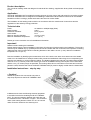
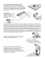
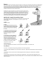
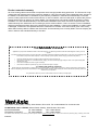
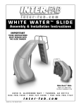
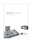
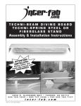
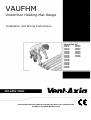
VAUFHM
Underfloor Heating Mat Range
Installation and Wiring Instructions
Stock Ref. N°
446175
446176
446177
446178
446179
446180
446181
446182
446183
446184
446185
446186
446187
446188
446189
446190
446191
220-240V~50Hz
PLEASE READ INSTRUCTIONS IN CONJUNCTION WITH THE ILLUSTRATIONS.
PLEASE SAVE THESE INSTRUCTIONS
446192
446193
446194
446195
446196
446197
446198
446199
446200
Product description
Twin conductor heating cable mat designed for electrical floor heating, supplied with factory fitted cold lead (length
2,5 m).
Application
The BLUE THERMAL MAT is suitable for heating all types of indoor rooms and well suited for renovation projects.
The BLUE THERMAL MAT is designed for embedding in adhesive/mortar/screed/concrete and can be installed
beneath most floor coverings, please see these instructions for further details.
The installation of this heating product shall be in accordance with the manufacturer’s instructions and the
regulations of the authority having jurisdiction.
Technical data
Power:
Rated Voltage:
Conductor insulation:
Outer sheath:
Minimum bending diameter:
Minimum installation temperature:
As stated on cable/package (Watt)
230V~
Fluor polymer
PVC
40 mm (1 5/8”)
0 ºC (32 ºF)
Please go to www.vent-axia.com to find additional information.
Important!
Read this before starting the installation
Please read through the entire installation instructions (this document) before starting the installation. The product
should only be installed only by qualified personnel who are familiar with the construction and operation of heating
cables and the risks involved. Minimum bending diameter of the cable is 40 mm (1 5/8”). Minimum installation
temperature is 0 ºC (32 ºF).
Plan the installation by identifying the heated area, which is the entire room area minus areas not to be heated.
Areas not to be heated are for example areas under permanent installations without legs, thus encapsulat-ing the
area they are standing on, and not allowing airflow. The distance between the mat and non-heated areas shall be
minimum 3 cm (1,2 inches). Select the correct type of BLUE THERMAL MAT(S) with respect to the heated area
and the 3 cm (1,2 inches) margin as specified. The heating cable cannot cross neither touch itself and cannot be
placed in a wall, therefore the area of the BLUE THERMAL MAT(S) must be slightly smaller than the heated area.
Installation instructions – step by step
1. Caution!
Handle the product with care and do not press or
drop sharp objects into the BLUE THERMAL MAT.
2. Measure and check the following electrical properties
to be within limits before installing the BLUE THERMAL
MAT:- The ground insulation between the earth wire and
the resistance wires: 100 MOhm or higher.- The resistance
value of the heating element: Within -5/+10% of nominal
value. Enter the results into the warranty form.
2
3. It’s recommended to treat the sub floor with a primer
so that mat can be easily fixed to the underlay. Apply the
primer with a brush, and leave to dry. Do NOT apply a
primer later on, after the heating cable mat has been installed,
as this might dissolve the adhesive on the net.- BLUE THERMAL
MAT 100 W/m² can be installed on any type of stable and levelled
sub-floor.- BLUE THERMAL MAT 150 W/m² must be installed on a
non-combustible sub-floor (leveled and stable) with minimum
thickness 5 mm.
4. IMPORTANT!
Please investigate if the cold lead
attached to your heating
mat/cable has got a hidden splice
marked with -> SPLICE <-, or
a manual splice identified as a bulge
on the cable:
Regardless of SPLICE type, the SPLICE has to be placed embedded into the heated floor, and NOT inside the
wall or other non-heated area: Install and adjust the BLUE THERMAL MAT by rolling out the mat on the sub-floor.
Beware! When making adjustments: Do not cut the cable, only the net. BLUE THERMAL MAT is self-adhesive, and
is fixed by applying a light pressure. When cutting and adjusting the mat, ensure that the cables are kept at the
same distance from each other as the cables on the mat itself. Make sure that the splice (the connection between
cold and hot part of the cable) is placed so the cold lead reaches the thermostat, and that the splice itself is placed
in the floor and not inside the wall. If other cables (which are not a part of the heating cable installation) are
embedded in the heated floor these must be placed at least 3 cm (1,2 inches) away from any heating cable. The
current-carrying capacity of these cables must be adjusted due to the heated surroundings. If a floor sensor is used
it must be connected at equal distance between two cable strands. It’s recommended to install the floor sensor
inside a tube, making it possible to replace it in the future.
5. Measure the ground insulation and conductor resistance
again before pouring the adhesive/screed/mortar/concrete.
Enter the results into the warranty form.
6. When embedding use cement-based tile adhesive,
thinset mortar, screed or concrete, suitable for heated floors
with good heat conductivity. As a minimum the BLUE
THERMAL MAT must be covered entirely by the
adhesive/screed/mortar /concrete, but a thicker layer might be
required to ensure mechanical floor stability. Follow the
guidelines given by the manufacturer and ensure that the BLUE
THERMAL MAT is fully embedded.
3
Attention!
Use machinery to mix well and pour shortly after mixing. After pouring compact thoroughly to avoid a porous slab
with air pockets.
7. Some materials are sensitive to heat and are
not applicable to install as a part of a heated floor.
Please check with the manufacturer of the floor covering
whether their product is suitable or not.
Area power specific rules
BLUE THERMAL MAT 100 W/m² can be installed beneath most types of floor covering. That includes wood,
laminate, parquet, vinyl, tiles, slate, stone, marble, etc.*
BLUE THERMAL MAT 150 W/m² must be installed beneath non-combustible materials. Examples of such
materials are tiles, slate, stone, vinyl, linolium and marble.
In addition the following thermal resistance rules apply
Total thermal resistance of the floor covering (incl. carpets or similar) shall not exceed a value of R 0,85 [ft² °F h /
Btu] corresponding to RSI 0,15 [m²K / W].
Typical R-values (thermal resistance [ft² °F h / Btu]) of top floor coverings
Material
Typical thickness
R-value
Ceramic Tiles
6 mm
R 0,24
Vinyl-/Linoleum
4 mm
R 0,25
Laminate
6-7 mm
R 0,45
Parquet
13-16 mm
R 0,51
Solid wood oak
16 mm
R 0,54
Solid wood pine/spruce
16 mm
R 0,82
Cork
4-8 mm
R 0,47 - 0,94
Thin carpet, synthetic
6 mm
R 0,66
Thin carpet, wool
6 mm
R 0,99
Thick carpet, wool
12 mm
R 1,99
Typical RSI-values (thermal resistance [m²K / W] ) of top floor coverings
Material
Typical thickness
RSI-value
Ceramic Tiles
6 mm
RSI 0,042
Vinyl-/Linoleum
4 mm
RSI 0,044
Laminate
6-7 mm
RSI 0,080
Parquet
13-16 mm
RSI 0,090 - 0,111
Solid wood oak
16 mm
RSI 0,095
Solid wood pine/spruce
16 mm
RSI 0,145
Cork
4-8 mm
RSI 0,083 - 0,166
Thin carpet, synthetic
6 mm
RSI 0,116
Thin carpet, wool
6 mm
RSI 0,175
Thick carpet, wool
12 mm
RSI 0,350
Which means some wooden and cork floors should not be installed above BLUE THERMAL MAT, and also some
types of carpets should not be placed on heated floors.
4
Beware!
Some wooden floors are sensitive to heat with respect to cracking and contracting and shouldn’t be heated above
28 ºC (83 ºF). Also, some vinyl and linoleum coverings can be sensitive to heat with respect to discolouring. To
solve this and prevent high floor temperatures a limiting thermostat with a floor sensor can be installed.
Recommended limiting temperature (measured between two cables in the floor) is 35 °C. Please also see the
guidelines described in the user manual section.
8. Measure the ground insulation and conductor resistance again before
connecting to the thermostat as a final test. The heating cable must be con
nected to electrical earth properly and always be protected by a ground
fault circuit breaker (RCD/GFCI), maximum trip level 30 mA. Connecting
more than one heating cable mat to a thermostat is possible, but make
sure the total power [W] does not exceed the limit of the thermostat.
IMPORTANT! CONNECTION INSTRUCTIONS
The cold lead has an information text on it, showing the cross section area
of the copper conductors. This will either be 1,0 mm² or 0,5 mm². The
following apply:
1,0 mm²
Connect normally.
0,5 mm²
If connecting one conductor (0,5 mm²)
to a pillar terminal without pressure plate,
attach a metal crimp (use crimping tool)
to the connecting end before fastening
the screw.
If connecting one conductor (0,5 mm²)
to a pillar terminal with pressure plate,
the conductor can be connected and
fastened normally like a 1,0 mm²
conductor.
If connecting two or more conductors
into the same terminal (regardless of
type) do the following: Attach a metal
crimp (use crimping tool) over any
0,5 mm² conductor(s) and place the
crimp(s) covering the conductor(s) into
the terminal. Then fasten normally.
Complete the warranty form.
Standards/approvals
The BLUE THERMAL MAT is tested in conformity with IEC EN 60335-1, IEC 60335-2-96.
User Manual
To ensure a comfortable and long lasting heated floor follow these guidelines:
• The heating cable installation is not to be turned on before the adhesive/mortar/screed/concrete has hardened
naturally.
• Thermostat or other controls must be used and programmed according to the manufacturer’s installation
instructions.
• Do NOT attach screws, bolts, nails or similar into the heated floor. If this must be done seek help from an
electrician whom might be able to locate the heating cables. The documentation of the installation will also contain
useful information.
5
• Avoid high temperatures:
- In rooms with an area power larger than 100 W/m² carpets shall not be used. Caution is to be taken when placing
thermally insulating items on the floor such a diaper packages, heaps of clothes and so on.
- In rooms with an area power of 100 W/m² or less, pay attention when placing thermally insulating items on the
heated floor, for example; carpets, furniture without feet.
- Be aware that some vinyl/linoleum floors are sensitive to heat, discolouring of the floor can occur at high
temperatures. Consult the manufacturer for more information.
- Furniture and other permanent installations which are to be placed in the room must either have legs allowing
heat to be dissipated from the floor, or be placed in floor areas without heating.
6
VAUFHM WARRANTY FORM
Installed by (Company):
Installation address:
Room/area:
Rated values
Cable type(s):
Single-/Twin conductor:
Linear output:
Rated resistance:
Rated voltage:
Check measurements
Before installation
Before pouring
Element resistance (-5/+10%):
Insulation resistance (>100 MOhm):
Construction details
Installation depth:
No. of elements/mats installed:
Installed/heated area:
Area output in heated area:
Size circuit breaker:
Trip level RCD/GFCI (ground fault protection):
Earthed cable screen:
Earthed chicken wire:
Other (specify):
Max. temperature in construction is limited to 80 ˚C by:
Planning:
Installation:
Limiting/protecting equipment (specify):
Control system
Designation of type:
Floor sensor
Room sensor
Other specify
Installer statement
The heating cable product is installed according
to Vent-Axia installation instructions and the
building owner has been informed about precautions
and limitations which apply to heated floors.
Date/signature/stamp:
Special notes about this installation
Building owner / Purchaser
Warranty form and user manual has been received, read and understood.
Date & Signature
7
m²
W
Before connecting
Date & signature
cm
stk/st/kpl/pieces
m²
W/m²
A
≤30mA
Product extended warranty
All of our heating cable units and their components are thoroughly tested during production. The final test is a high
voltage test and measurement of the conductor resistance. Only the units which have passed the tests, are sent to
the market. Vent-Axia offers an extended 10-year warranty on defects in material and workmanship in the sold
product, under proper and normal use and service. In case of a defect, Vent-Axia will repair or replace the product.
Please see the terms of warranty for further details. The warranty does not extend to defects caused by a faulty
installation. For the extended warranty to be valid these installation instructions must be accompanied with. The
written warranty form inside each box containing a product must be filled in. This is to ensure a correct installation
and that no damage has been done to the product during the installation. If, during the installation, a heating cable
is damaged, it will have to be replaced before the construction is finished. Vent-Axia must be given notice of any
defect within 30 days after the defect was discovered, and the warranty form correctly filled in must accompany the
claim in order for the extended warranty to be valid.
The abc Guarantee
Applicable only to products installed and used in the United Kingdom. For details of guarantee outside the United Kingdom contact your local
supplier.
Vent-Axia guarantees its products for two years from date of purchase against faulty material or workmanship. In the event of any part being found
to be defective, the product will be repaired, or at the Company’s option replaced, without charge, provided that the product:•
•
•
•
Has been installed and used in accordance with the instructions given with each unit.
Has not been connected to an unsuitable electricity supply. (The correct electricity supply voltage is shown on the product rating label
attached to the unit).
Has not been subjected to misuse, neglect or damage.
Has not been modified or repaired by any person not authorised by the company.
IF CLAIMING UNDER TERMS OF GUARANTEE
Please return the complete product, carriage paid to your original supplier or nearest Vent-Axia Centre, by post or personal visit. Please ensure
that it is adequately packed and accompanied by a letter clearly marked “Guarantee Claim” stating the nature of the fault and providing evidence of
date and source of purchase.
The guarantee is offered to you as an extra benefit, and does not effect your legal rights
Head Office: Fleming Way, Crawley, West Sussex, RH10 9YX. Tel: 01293 526062 Fax: 01293 551188
UK NATIONAL CALL CENTRE, Newton Road, Crawley, West Sussex, RH10 9JA
SALES ENQUIRIES:
Tel: 0844 8560590
Fax: 01293 565169
TECHNICAL SUPPORT:
Tel: 0844 8560594
Fax: 01293 539209
For details of the warranty and returns procedure please refer to www.vent-axia.com or write to Vent-Axia Ltd, Fleming Way, Crawley, RH10 9YX
446257A
0111
8