1
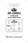
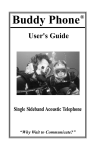
Undersea Systems International, Inc.
dba
OCEAN TECHNOLOGY SYSTEMS
Diver Recall System
DRS-100
Mod B
User’s ManuaL
“Technology in Depth”
- IMPORTANT SAFETY NOTICE It is absolutely essential that all users are properly trained and equipped and fully
understand this user’s manual before attempting to use the DRS-100 (mod B) Diver
Recall/Hydrophone System.
Read and fully understand the battery charging section of this manual before you
attempt to charge or operate the DRS-100.
While the DRS-100 provides divers with good underwater communications, it does
not change or eliminate the potential hazards of diving!
- NOTE This manual and the information contained herein are provided for use as a maintenance and operation guide. No license or rights to manufacture, reproduce, and/or
sell either the manual or the articles described herein are given. Ocean Technology
Systems reserves the right to change specifications without notice.
Refer to the Library page of our Web site, www.oceantechnologysytems.com,
for a list of any changes made to this manual since its publication.
© Copyright 1994, 2008 by Undersea Systems International, Inc., dba
Ocean Technology Systems. All rights reserved.
Specifications are subject to change without prior notice.
i
506016-000 (rev. J)
Table of Contents
Section 1: Introduction ................................................................................1
1.1
Specifications....................................................................................2
1.2
Features and Functions.....................................................................3
Section 2: Setup and Operation ..................................................................5
2.1
Setup.................................................................................................5
2.2
Operation...........................................................................................5
2.2.1 Power and Volume Control.................................................5
2.2.2 Transmission.......................................................................6
2.2.2.1 Tone/Recall Mode................................................6
2.2.2.2 Voice Communication..........................................6
2.2.2.3 External Audio.....................................................6
2.2.3 Recording...........................................................................6
Section 3: Batteries and Charging ..............................................................7
3.1
Battery Charging Procedure..............................................................7
3.2
Battery Removal/Replacement.........................................................8
Section 4: Maintenance and Troubleshooting . ....................................... 10
4.1
General............................................................................................10
4.2
Preventive Maintenance..................................................................10
4.2.1 Check Prior to Every Dive...............................................10
4.2.2 Maintenance Following the Dive.....................................10
4.3
Troubleshooting..............................................................................11
4.4
Removal or Replacement of Parts...................................................11
4.4.1 Electronics Chassis Removal...........................................11
4.4.2 Battery Replacement........................................................11
4.4.3 Fuse Replacement.............................................................11
Appendix: Spare Parts . .............................................................................12
Limited Warranty ......................................................................................13
Illustrations
Figure 1: Layout of the DRS-100B.................................................................3
Figure 2: Battery Compartment Layout..........................................................9
Tables
Table 1: Troubleshooting...............................................................................11
ii
SECTION 1
INTRODUCTION
Thank you for choosing the Ocean Technology Systems DRS-100 (mod B) Diver
Recall/Hydrophone System. With the DRS-100, you can recall free-swimming
divers with a solid tone, intermittent tone, or voice transmissions. The underwater
listeners need not wear any special diving equipment to hear. Topside personnel
can even transmit music or any other audio signal by connecting the source to
the line-in jack on the DRS-100 panel. The DRS-100 can even be used as a hydrophone, allowing the user to listen to marine biological and man-made sounds
present in the water. These sounds can be recorded easily via the external record
output jack on the front panel.
How do the divers hear? Sound is transmitted through the water omnidirectionally
by an underwater transducer. The typical range is 500 meters but depends on the
biological/ambient noise level. Divers within range listen using only their ears;
no electronic equipment is necessary.
The DRS-100 Diver Recall System provides the following:
• A self-contained control module with a housing that is sturdy, resistant to marine
corrosion, o-ring sealed, and constructed of lightweight materials
• A transducer attached to 25 feet of cable
• An HSM-10 hand-held microphone with a push-to-talk button
• Two maintenance-free rechargeable batteries
• An RCS-30 smart charger
Before operating or charging the DRS-100 Diver Recall System, read this entire
manual. In addition to the instructions for use and maintenance of the system, there
are some important safety issues all users must be familiar with before operation.
Should you have any questions, please contact your local Ocean Technology Systems (OTS) dealer, or feel free to contact OTS directly (see p. 13 for OTS contact
information).
1
1.1
SPECIFICATIONS
Input voltage:
24 VDC
Input current:
7 amps maximum
Idle current:
75 mA
Audio power (PEP*):
Recall & tone: 132 watts
Voice:
132 watts
Frequency response:
500–4000 Hz
Recall oscillation rate:
5 Hz
Beam pattern:
Omnidirectional
Transducer cable:
25 feet in length
Transducer:
Anodized aluminum
Fuse type:
6 amps, slow-blow (use slow-blow fuse only)
Transducer:
Size: 9 in. diameter, 6 in. axial length
Weight: 13 lbs. in air, 2 lbs. in water
Low-battery LED:
Flashes at approximately 20 volts
Battery type:
Two 12-volt, 2.6 amp-hour, maintenance-free rechargeable cells (in series)
Battery life:
5 hours at 20% duty cycle (Recall/Tone mode)
3 hours nominal when using auxiliary input (medium
volume)
Microphone type:
Push-to-talk, front panel (optional hand-held with
PTT available)
Size:
Depth: 10.6 in. (including handle and hinges)
Length: 14 in.
Height: 4.7 in. without cover
6.5 in. with cover
Weight:
15 lbs.
Battery charging time:
2-3 hours (the RCS-30 automatically switches to
maintenance mode when the battery is fully charged,
indicated by the LED turning green)
RCS-30 smart charger:
90–260 VAC input; 24 VDC, 1300 mA, 50/60 Hz output
* Peak envelope power
2
Figure 1. Features of the DRS-100B
1.2
FEATURES AND FUNCTIONS
Refer to Figure 1. Terms in all capital letters correspond to the labels on the DRS100 panel.
1. REC. OUT: This female RCA jack allows topside personnel to record underwater sounds. Use a male RCA plug and any recorder.
2. LOW BATT.: This LED will illuminate red (flashing) when the battery level
reaches approximately 20 volts. The unit can operate with as little as 12 volts.
Note: Recharge the batteries as soon as possible after the low-battery light
illuminates.
3. PWR. ON: This green LED will illuminate when power is on.
4. TONE/RECALL: This LED illuminates red when the continuous tone is
utilized and green when the intermittent tone is activated.
5. Panel Relief Valve: Open this valve when charging the internal rechargeable batteries. It must be completely open (counterclockwise) when charging
(see charging instructions), and closed during normal operation to prevent
water from entering the housing.
Also be sure to open the valve to maintain equalized pressure if the DRS-100
will undergo airline shipment.
6. XDUCER: This jack is used to connect the underwater transducer to the DRS100 unit.
7. EXT PWR/CHG: This jack is used to charge the internal batteries or to use
3
the optional EXT-24 external power supply (p/n 910091-000) (115 volts AC
input to 24 volts DC output) (+ red, – black).
8. Hydrophone VOLUME: Clockwise rotation past the detent turns the unit
on, indicated by the green “PWR ON” LED’s (#3) illumination if the battery
condition is good. This knob controls volume to the front-panel speaker. All
sound in the water within range will be amplified through this speaker. Rotation clockwise increases, and counterclockwise decreases, listening volume to
the front-panel speaker. Full counterclockwise rotation past the detent turns
the DRS-100 off.
9. Housing Relief Valve: This valve automatically equalizes internal pressure
during air travel.
10. Front-Panel Screws: There are ten Phillips screws located around the front
panel. Each screw has its own o-ring seal. When removing the screws and
front panel, ensure that you do not lose or damage the o-rings. Tighten the
screws only enough to ensure the panel is sealed against its o-ring.
11. LINE IN: This RCA jack allows the operator to transmit an external audio
source into the water (e.g., cassette recordings or inputs from a master public
address system).
12. Front-Panel Speaker: The front-panel speaker is used to listen to any underwater sounds within range (e.g., biological or from human activity). The
hydrophone volume control (#8) adjusts the listening volume.
13. Handle: You will find two handles on the front panel. Use these to remove
the front panel after the ten front-panel screws (#10) are removed.
14. TONE/RECALL: When this toggle switch is pushed and held to the left, the
unit will emit a continuous tone, while the Tone/Recall LED (#4) illuminates
red. Push and hold the toggle switch to the right for the DRS-100 to emit an
intermittent tone, indicated by green illumination of the same LED.
15. MIC.: This jack is used to connect an HSM-10 hand-held microphone to the
unit. Voice transmission can now take place via the hand-held microphone.
Without the hand-held microphone, voice transmission can be accomplished
via the front-panel speaker (#12) and PTT button (#16).
16. PTT: This is a push-to-talk (PTT) control. When the DRS-100’s power is
on, the user can depress and hold the PTT button and talk into the front-panel
speaker. His voice will be received by all divers within range. The volume
to the divers is controlled via the transmitter volume control (#17).
17. Transmit VOLUME: This control adjusts the volume to the divers. Rotation
clockwise increases and counterclockwise decreases the volume. Generally
three fourths of a turn clockwise is the best position.
4
SECTION 2
SETUP and OPERATION
2.1
SETUP
1. Set the DRS-100 Diver Recall/Hydrophone System on a flat surface where
you will use it, with the carrying handle facing the user.
2. Open the housing by pulling up on the clamps located on either side of the
carrying handle, and raise the lid.
3. Fully close the relief valve (Fig. 1, #5) on the panel by rotating it clockwise.
4. If you will use an external power source, connect its banana plugs to the “EXT
PWR/CHG” jack (Fig. 1, #7) on the DRS-100 panel, being careful to observe
polarity (match the red and black). Activate the external power source, if
necessary, but leave the DRS-100 power off. If you will use the internal batteries, proceed to Section 3 (Batteries and Charging, p. 7) before continuing.
5. Remove the protective cover from the transducer receptacle (Fig. 1, #6).
6. Locate the connector on the transducer (underwater speaker) end of the transducer cable. Insert the transducer connector into the transducer receptacle on
the panel, and rotate the ring until a good connection is obtained.
7. Strain-relieve the transducer cable by securing a rope to the strain relief clip
on the transducer. Additionally, tape the rope about every 12 inches to the
transducer cable, with all of the strain on the rope.
8. Lower the rope secured to the transducer into the water, and secure the rope
to a solid object above the surface.
Note:
• Never lower the transducer into the water without a rope to relieve the
strain, or damage may occur. The transducer cable alone will not support
the weight of the transducer.
• Do not lower the transducer deeper than 25 feet.
2.2
Operation
2.2.1 Power and Volume Control: To activate the unit’s power,
rotate the speaker volume control (Fig. 1, #8) clockwise. The green “PWR ON”
LED (Fig. 1, #3) should illuminate. To adjust the hydrophone listening volume,
turn the speaker volume control (clockwise rotation increases the volume).
The hydrophone is listening as soon as you turn on the DRS-100. If you do not
want to listen to the front-panel speaker, turn the volume down. However, do not
turn the unit completely off.
2.2.2
Transmission:
5
2.2.2.1 Tone/Recall Mode: For tone transmission, move the “TONE/RECALL”
switch (Fig. 1, #14) either right for intermittent tone or left for continuous tone. The
tone/recall LED (Fig. 1, #4) illuminates green when the DRS-100 is in intermittent
tone mode and red when in continuous tone mode.
Note: The volume control knobs do not affect the volume when using the tone/
recall feature. Transmit volume control is used to control the volume only when
in PTT or hand-held microphone mode. Tone/recall mode automatically puts full
power to the transducer.
2.2.2.2 Voice Communication: For voice communication to divers or swimmers,
set the transmitter volume (Fig. 1, #17) to about half volume. If you will use a
hand-held microphone (e.g., the HSM-10) with a push-to-talk (PTT) switch, insert
the microphone connector into the jack (Fig. 1, #15), depress the PTT button, and
talk into the microphone. Otherwise, press and hold the PTT switch (Fig. 1, #16)
and talk into the front-panel speaker (Fig. 1, #12). To increase the transmission
volume, rotate the transmit volume control (Fig. 1, #17) clockwise. Release the
PTT button when you have finished transmitting.
2.2.2.3 External Audio: To transmit audio from an external source, connect an
RCA plug leading from the source to the DRS-100’s “line-in” jack (Fig. 1, #11).
Note:
• When a standard line-out source is connected to the “line-in” jack, the transmitter activates. If your sound source has no DC path to ground (DRS-100 chassis
ground) via the output circuit of your device, you may need an adapter (OTS p/n
914024-000). Additionally, be careful not to allow salts, water, minerals, etc. to
build up around this jack, because they could cause the transmitter to activate
due to electrical conduction at the jack.
• The line input connection will accommodate unbalanced line signals (2 VPP at
600 ohms). Any source level similar to this is suitable for driving the DRS-100
line input. The source must present a DC path of at least 15 Kohms to ensure
the transmit circuit activates.
2.2.3 Recording: To record audio signal received from the hydrophone or
that you transmit into the water, insert a male RCA plug into the record-out jack
(Fig. 1, #1). Connect the other end to your recorder’s microphone input.
6
SECTION 3
BATTERIES and CHARGING
The DRS-100 Diver Recall System is equipped with rechargeable, maintenance-free
batteries (two 12-volt batteries wired in series) and comes with an RCS-30 smart
charger. It is not necessary to remove the batteries to recharge the system.
Note: The battery you receive may have upgraded specifications from what is stated
in this manual. Due to advancing battery technologies, we continually upgrade
our batteries and chargers. Contact OTS (p. 13) or your local OTS dealer to find
out the latest available battery and charger.
The DRS-100 can be powered by an external 24-VDC, 7-amp power source (the
EXT-24 external power supply, sold separately, is available to convert 115 VAC to
24 VDC) or by its internal rechargeable gel-cell batteries. If an external 24-VDC
power supply is used, the internal batteries will partially recharge. The charging
source must provide at least 28 volts, 500 mA for batteries to come to a fully
charged condition.
When the low-battery LED (Fig. 1, #2) begins to flash red, the battery voltage has
decreased to 20 volts. Although the DRS-100 can operate with as little as 12 volts,
we recommend that you recharge the batteries (Section 3.1) as soon as possible
after the LED starts to illuminate. If the batteries no longer hold a charge, replace
them (Section 3.2).
3.1Battery Charging Procedure
Warning: To avoid damage or injury, read and follow all the instructions below
before attempting to recharge the batteries.
If you are going to operate the DRS-100 outside the USA, you will need to purchase
the appropriate power cord for the region of operation. Power cords are available
for: Australia (606014-003), UK (606014-002), and Europe (606014-001).
1. Open the cover.
2. Turn the relief valve (Fig. 1, #5) fully counterclockwise to open it.
3. Locate the 24-volt “EXT PWR/CHG” jack (Fig. 1, #7), and insert the plugs
(+ red and – black) from the RCS-30 smart charger.
Note: Be certain that black is connected to black and red to red. If they
are reversed, no harm will occur to the DRS-100, but the batteries will not
charge.
4. Connect the RCS-30 smart charger to any power source providing between
90 and 260 volts AC, 50 or 60 Hz.
5. The red LED on top of the battery charger should illuminate to indicate the
charger is properly connected. The charger may be disconnected when the
7
LED turns green, indicating a full charge, or may be left connected indefinitely
as the charger automatically switches to the “maintenance charge” mode.
- IMPORTANT SAFETY WARNING NOTES • Batteries can excrete hydrogen gasses during the charging cycle. To minimize gas build-up, open the pressure relief valve (Fig. 1, #5 ) on the panel
while recharging the batteries. Do not release the pressure relief valve and
turn on the DRS-100 until a minimum of 15 minutes have elapsed after the
charging cycle has been completed and the charger is disconnected from
the front panel. Failure to follow this procedure may result in damage to the
unit or serious injuries due to an explosion!!!
• Never use the RCS-30 smart charger to charge only one 12-volt battery.
Damage or injury may occur.
6. After a charging period, remove the RCS-30 smart charger from the power
source.
7. Disconnect the red and black charging plugs from the front panel.
8. After a resting period of at least 15 minutes, rotate the panel’s relief valve
clockwise to its closed position.
Note: The RCS-30 smart charger cannot be used as an external power supply. It
does not supply enough current.
3.2Battery Removal/Replacement
If the batteries no longer can hold a charge, you will need to replace them with the
Ocean Technology Systems RB-30 battery kit. Follow this procedure to remove
and replace the batteries:
1. Remove the ten front-panel screws (Fig. 1, #10).
2. Gently remove the control panel by pulling on the handles (Fig. 1, #13).
3. Disconnect the panel’s connectors from P8, P10, P11, P12, and P13 of the
circuit board.
4. Remove the battery jumper (Fig. 2, #19) and the interconnection cable (#18)
from the batteries.
5. Remove all the hex nuts (Fig. 2, #22) from the battery brackets.
6. Remove the battery bracket (Fig. 2, #23) from the batteries.
7. Remove the batteries (Fig. 2, #24).
8. Slide the new batteries into place.
9. Reinstall the battery bracket, and secure it with the hex nuts.
10. Connect one end of the battery jumper (Fig. 2, #19) to a terminal marked
“BLACK” on one of the new batteries.
8
11. Connect the other end of the battery jumper to the red terminal of the other
battery.
12. Connect one end of the interconnection cable (Fig. 2, #18) to the remaining
black and red terminals.
13. Reconnect J8, J10, J11, J12, and J13 to the circuit board assembly. J10, J11,
J12, and J13 are labeled and should be connected to the corresponding plugs
on the circuit board (P10, P11, etc.). J8 is probably not labeled but is the one
remaining connector of the wiring harness that attaches to the circuit board;
it should be connected to P8.
14. Check the o-ring (Fig. 2, #21) on the inside of the housing for debris or damage. Replace it if necessary.
15. Reinstall the front panel and the ten front-panel screws (just tightly enough to
make a good seal).
16. Fully charge the batteries (Section 3.1, p. 7).
Figure 2. Battery Compartment Layout
Key
18.
19.
20.
21.
Battery interconnection cable
Battery jumper
Housing
Housing o-ring
22. Hex nut, #8-32 (battery bracket mounting)
23. Battery bracket
24. Battery
9
SECTION 4
MAINTENANCE AND TROUBLESHOOTING
Solidly designed and ruggedly constructed, the DRS-100 Diver Recall/Hydrophone
System should provide long, trouble-free operation if basic preventive maintenance
is performed regularly according to the instructions in this section. Information for
troubleshooting is also provided in the event a malfunction does occur.
4.1
GENERAL
This section provides information for maintenance, functional checks, and adjustments of the DRS-100 Diver Recall System. The preventive maintenance portion
(Section 4.2) serves as a guide in proper maintenance of the DRS-100 to prolong its
service life and avoid performance failures. The troubleshooting portion (Section
4.3) provides the necessary information and procedures for solving basic problems
that may arise and seeking further assistance if a service technician is needed. Removal and replacement procedures are provided for various parts to assist during
maintenance and troubleshooting. A list of recommended spare parts appears in the
Appendix at the end of the manual. For service personnel or technically inclined
users, documentation for more advanced troubleshooting of the DRS-100 is available from Ocean Technology Systems (see p. 13 for contact information).
4.2
PREVENTIVE MAINTENANCE
The DRS-100 system must be maintained properly for trouble-free operation.
4.2.1 Check Prior to Every Dive: Perform the following checks on
the DRS-100 before every dive.
1. Examine the DRS-100 unit, checking for any damage to the exterior.
2. Open the lid and check for any damage to controls or connectors.
3. Check the connectors for bent or corroded pins.
4. Check the microphone and transducer cables for cuts and abrasions.
5. If the low-battery LED is flashing, charge the unit prior to use (Section 3.1, p.
7). If the batteries do not charge, replace them (Section 3.2, p. 8).
4.2.2 Maintenance Following the Dive: After each dive, the
following preventive maintenance should be performed.
1. Charge the batteries (Section 3.1, p. 7) if the voltage is low (the low-battery
LED is flashing).
2. Disconnect all connectors from the front panel.
10
3. After use, remove any salt spray or moisture accumulated on the front panel
(use a damp cloth with a mild detergent solution).
4. Remove any debris from the o-ring located on the inside of the cover (Fig. 2,
#21).
5. Rinse the transducer in fresh, clean water, and dry it before storage.
6. Keep the hand-held microphone as dry as possible (if applicable).
7. Keep the bulkhead connector free of debris and moisture.
8. Lubricate the seals with Zip Slip silicone grease or equivalent. If the seals
show wear or damage, replace them instead.
4.3
TROUBLESHOOTING
This section contains instructions for troubleshooting the DRS-100 Diver Recall
System. The information found in Section 2, Setup and Operation (p. 5), should
be used to supplement the information in this section.
Refer to Table 1 for instructions for troubleshooting basic problems with your
DRS-100. If the problem you are experiencing is not mentioned in the table, or
if you have tried the suggested solutions and the problem persists, contact Ocean
Technology Systems (see contact information on p. 13) for technical support or
arrangements to send in the unit for repair.
4.4
REMOVAL OR REPLACEMENT OF PARTS
4.4.1 Electronics Chassis Removal: To remove the electronics
chassis from the housing, remove the ten panel screws. Carefully pull the electronics chassis straight out, taking care not to catch any wiring on the edge of the box
or to place undue stress on the circuit board connectors or cables.
4.4.2Battery Replacement: If the battery pack fails and requires
replacement, remove the battery container and replace the batteries (Section 3.2,
p. 8).
4.4.3 Fuse Replacement: If the fuse blows, replace it with a 6.0-amp,
type MDL-6 slow-blow fuse. This fuse is located on the internal board.
Table 1: Troubleshooting
Symptom
No power to unit
Probable Cause
Remedy
Batteries exhausted
Recharge batteries.
Failure of external DC
power supply
11
Check DC power source and connection.
Symptom
Probable Cause
Batteries do not charge
Fuse F1 open
Replace fuse.
Batteries defective
Replace batteries.
Charger defective
Replace charger.
Battery terminals loose
No microphone input
Remedy
Check connections
(tighten if necessary).
Microphone defective
Replace microphone.
Microphone connector
defective
Replace connector.
No transmission or
Defective U/W speaker, con- Replace speaker or
reception
nector, or cable
speaker connector, or
repair cable.
Loose or disconnected Molex connector to output
transformer
Reconnect.
Output transformer defective Replace transformer.
Panel speaker defective
Replace panel speaker.
-APPENDIX-
SPARE PARTS
• LL-98: transducer with strain-relief eyelet (p/n 900189-000)
• HSM-10: deluxe, noise-cancelling hand-held microphone (p/n 910041-000)
• Line-in adapter cable (p/n 914024-000) (optional)
• RCS-30: smart charger with connector (p/n 910363-000 thru -003)
• RB-30: two maintenance-free, 12-volt batteries (p/n 900041-000)
• Fuse: 6-1/4 amps, slow-blow (p/n F007)
• Housing, Underwater Kinetics (p/n 134033-001)
• Housing o-ring (included with housing)
• Hex nut, 8-32, for mounting of battery bracket (p/n 246007-000)
• Battery bracket (p/n 136007-000)
• Battery interconnection cable (p/n 914023-000)
• US power cord for RCS-30 (p/n 606014-000)
• European power cord for RCS-30 (p/n 606014-001)
• UK power cord for RCS-30 (p/n 606014-002)
• Australian power cord for RCS-30 (p/n 606014-003)
12
Undersea Systems International, Inc.
dba
Ocean Technology Systems
LIMITED WARRANTY
Ocean Technology Systems’ DRS-100 mod B is fully warranted
against defects in materials and workmanship for a period of
one year from the time of purchase. Our obligation under this
warranty is limited to the replacement of any part or parts that
prove to our satisfaction to have been defective and that have
not been misused or carelessly handled. Labor is warranted
for one year from time of purchase. The complete unit and/
or part must be returned to our factory, transportation charges
prepaid. We reserve the right to decline responsibility where
repairs have been made or attempted by other than an Ocean
Technology Systems factory-trained service center or properly
trained personnel. In no event shall Ocean Technology Systems
be liable for consequential damages.
Ocean Technology Systems
3133 West Harvard Street, Santa Ana, California 92704 USA
Toll-Free (800) 550-1984 • Telephone (714) 754-7848 • Fax (714) 966-1639
E-mail [email protected] • Web www.oceantechnologysystems.com
You can now register your product online at the OTS Web site. Just visit
http://www.oceantechnologysystems.com/register1.html.
© Copyright 1994, 2008 by Undersea Systems International, Inc., dba
Ocean Technology Systems. All rights reserved. Specifications are subject to change
without prior notice.
13