1
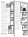
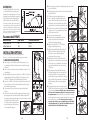
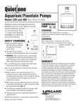
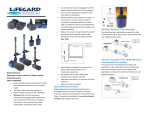
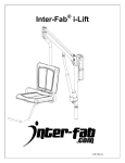
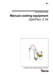
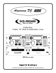
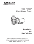
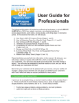
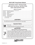
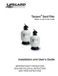
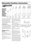
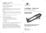
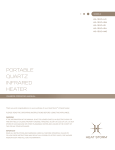
PARTS BREAKDOWN
FB300
Item Quantity Description Part#
1. 2 3/4” MPT x 1/2” Barb Elbow
270248
2. 4’
1/2” ID x 11/16” OD Valve Tubing
270247
3. 1
Check Valve Assembly 270245
4. 3
O-ring, Check Valve & Plugs
270228
5. 1
Tension Spring
270229
6. 1
#6 x 1/2” Screw
01045
7. 1
Tension Retainer
270222
8. 1
Mounting Bracket
270242
9. 1
Flow Control Valve
270220
10. 1
O-ring, Flow Control Valve
270227
11. 2
Valve Retainer Screw
01086
12. 1
Water Fall Assembly
270244
13. 2
Adjustment Screw
36021
14. 2
Plug
270218
15. 1 Media
270241
16. 1
Thread Seal Tape
175096
17. 3
Hose Clamp
175013 9.
7.
5.
6.
10.
4.
1.
3.
11.
12.
8.
11.
15.
13.
14.
13.
4.
16.
17.
WARRANTY: LIFEGARD AQUATICS warrants the original purchaser of this
equipment to be free from defects in workmanship or material for a period of one year
from the date of installation, provided this equipment is installed in accordance with
factory instructions and operated within the environment and limitations for which it
was designed.
Should any of the integral parts of the unit become defective within one year
from the date of purchase, they will be repaired or replaced, if proven defective in
workmanship or material in the opinion of the manufacturer.
LIFEGARD AQUATICS will not be liable for any labor cost of removing or replacing
component parts. This shall be the responsibility of the original purchaser, as will be the
shipping charge to Lifegard’s plant.
Damage or failure of any part of a unit covered by this warranty, which results from
causes directly, or indirectly connected with the installation, operation, environment,
use or willful abuse, including without limitations, improper repackaging and damage
INSTRUCTION SHEET
FB 300
INTRODUCTION
4.
2.
FLUIDIZED
BED FILTER
14.
incurred in shipping, is not covered by this warranty. Unless state law provides
otherwise, manufacturer will only be responsible for repair or replacement of any of its
products or parts there of that are found to be defective, and will not bear the cost of
any incidental or consequential damages arising out of the occurrence of such defect.
This warranty gives you specific legal rights and you may also have other rights
which vary from state to state.
Due to its unique shape, the Lifegard Fluidized Bed Filter is an extremely efficient
high capacity “biological” filter. Aquatic organisms excrete toxic ammonia as a
metabolic waste product with additional ammonia produced as food and other
organic matter breaks down and decomposes.
This toxic ammonia (NH3) is converted to
another toxic compound nitrite (NO2) by the
Nitrosomonas species of bacteria. The nitrite is
then converted to a relatively non toxic compound called nitrate (NO3) by the Nitrobacter species of
bacteria. This process is known as “nitrification”. A “biological” filter is a vessel where nitrification
occurs and soluable waste is removed. Beneficial bacteria attach to the media within the Lifegard
Fluidized Bed Filter creating a thin film around the sand
grains. Water is pumped up through the unit lifting the sand
into a “fluidized bed”. The beneficial bacteria attached to the
media draw in dissolved wastes (ammonia and nitrite) oxygen, supplied by Rainbow’s
exclusive water fall device and other required nutrients from the passing water converting
them to relatively harmless nitrate. The sand grains are in continual free fall through the water
resulting in an excellent transfer capability between the liquid and the bacterial film on the
media. The enormously high surface area combined with this excellent transfer capability
creates the perfect habitat for bacterial growth. In addition, the sand grains bump into each
other frequently knocking off excess debris and providing a self cleaning function which allows
new areas for bacterial growth.The Lifegard Fluidized Bed Filter has been tested and proven
to supply the highest level of effluent water quality and will respond quickly and efficiently to
severe changes in ammonia levels caused by over feeding or the addition of too many fish at
one time. To obtain highest water quality, a Lifegard Fluidized Bed Filter should be part of the
system.
CAPACITY
MODEL
FB 300
SYSTEM SIZE
Up to 300 Gallons
MEDIA WEIGHT
3 Lbs.
SURFACE AREA
214 ft2
Multiple units can be connected together for larger volume installations or systems with extremely high bio-loads.
Email: [email protected]
www.lifegardaquatics.com
FLOW RATE
The Lifegard Fluidized Bed Filter is most effective at low rates. Lower flow rates increase the contact time between the bacteria and the
toxic ammonia and nitrite compounds that they utilize.
5. UNDERNEATH AQUARIUM WITH A CANISTER FILTER
5A.Place filter in desired location next to the canister filter. Position the filter so
5A.
that it can be plumbed on the outlet side of the canister filter. In steps 5B
through 5E, refer to installation drawings in section #2 (Beside The Aquarium).
5B.Screw in the plugs on each side of the bottom manifold. Make sure the plug
“o” rings are seated properly. In most cases, the bottom inlet ports will not
be needed in this type of installation.
5C. Screw in the check valve assembly in top inlet port. Make sure check valve
“o” ring is seated properly.
5D.Wrap thread seal tape on the male threads of the two 3/4” MPT x 1/2” barb
elbow fittings provided. Wrap each fitting 5-7 times with thread seal tape.
5E. Screw one 3/4” MPT x 1/2” barb elbow fitting into the check valve assembly located at the top inlet port.
Screw in the other elbow fitting into the outlet port located at the top of the unit.
5G.Turn off the valve on the outlet side of the canister filter and completely drain the flexible tubing on the outlet
side of the canister filter. In most cases, it will be necessary to remove the “U” or “J” tube from the back of the aquarium. Cut the flexible tubing on the outlet side of the canister filter and plumb in line a by-pass valve and “tee” which will divert only a portion of the water from the canister filter and into the inlet port on the left side of the top manifold. Attach hose clamps and tighten accordingly.
5H.Attach one end of the 1/2” ID x 11/16” OD flexible tubing to the 3/4” MPT x 1/2” barb elbow located at the top
outlet side of the filter. Attach hose clamps and tighten accordingly.
5I. Place the other end of the tubing up and over the side or back of the aquarium so that the water returns to the aquarium and agitates the surface to aerate the system. In some cases, flexible tubing can be attached to a rigid plastic “U” or “J” tube (not supplied in this unit) that hangs on the aquarium. Attach hose clamps to the rigid tube and tighten accordingly.
5J. Add media to the unit by following steps H, I, J, K, and L in section #1 (Hanging On The Aquarium).
5K.Open the by-pass valve completely.
5L. Carefully adjust the fluidization level by following steps P, Q, and R in section #1(Hanging On The Aquarium).
5M.Partially close the by-pass valve to direct more water into the
filter only if proper fluidized is not achieved.
6A.
6. CONNECTING MULTIPLE UNITS TOGETHER
6A.Place each filter in desired location next to the aquarium system. Make sure
unit is level on base. If it’s more desirable to hang the filters on the side or
back of a aquarium or reservoir tank, please refer to steps E, F, and G in
section #1 (Hanging On The Aquarium).
6B. Screw in plug into the top inlet port on each filter. Screw in another plug into
the bottom inlet port on the right side of the last filter in line and the left side
of the first filter in line. Make sure the plug “o” rings are seated properly.
6C. Screw in check valve assembly into the inlet port on the right side of the
bottom manifold of first filter and the left side of the next filter.
6D. Wrap thread seal tape on the male threads of the two 3/4” MPT x 1/2” barb elbow fittings. Wrap each fitting 5-7 times with tape.
6E. Screw each of the 3/4” MPT x 1/2” barb elbow fittings into the outlet ports on the top side of
each filter. Position the barb portion of the fitting straight up vertically.
6
6F. Attach one end of the 1/2” ID x 11/16” OD flexible tubing to the 3/4” MPT x 1/2” barb elbow located at the top outlet side of the filter. Place the other end of the tubing up and over the side or back of the aquarium so that the water returns to the aquarium and agitates the surface to aerate the system. In some cases, flexible tubing can be attached to a rigid plastic “U” or “J” tube (not supplied in this unit) that hangs on the aquarium. Repeat this for each filter used. Attach hose clamps where needed and tighten accordingly.
6G. A by-pass valve may be needed depending on what size pump is used. The by-pass valve will divert only a
portion of the water from the pump to the filters. Refer to step 4E in section #4 (Underneath Aquarium with a Lifegard System).
6H. Add media to each filter by following steps H, I, J, K, L, in section #1 (Hanging On The Aquarium).
6I. Open by-pass valve completely.
6J. Carefully adjust the fluidization level of each filter by following the steps P, Q and R in section #1 (Hanging On The Aquarium).
6K. Partially close the by-pass valve to divert more water into the filters only if proper fluidization is not achieved.
ADDING REPLACEMENT MEDIA
Hanging Installations
A. Turn off pump and wait a full 10 minutes for the media to settle into the bottom chamber. If you have lost media, the level of the media will be below the “Media Fill Level” label located on the right side of the clear chamber.
B. Remove the retainer screws from the flow control valve located at the top outlet side of the filter.
C. Pull the flow control valve straight up and remove.
D. Pour in the media up to the “Media Fill Level” label on the unit. Wipe off any media that may be in the valve chamber
with a dry cloth. Lubricate the valve and valve chamber with
the Lifegard silicone lubricant supplied with the unit.
E. Install the flow control valve back into the valve chamber
making sure the “o” ring is seated properly and all parts are free of any debris or media.
F. Screw in the two valve retainer screws.
Below Tank Installations
A. Turn off pump to Lifegard Modular System or canister filter.
B. Completely drain flexible tubing on the outlet side of fluidized bed filter.
C. Follow steps A, B, C, D, E, and F in the above section (Adding
Replacement Media, Hanging Installations).
ADDITIONAL EQUIPMENT REQUIRED
Additional equipment is needed in order to achieve optimal
water quality in your aquarium. This is vital to the health of
your plants and animals as well as the nitrifying bacteria in your
fluidized bed filter. Accumulation of large amounts of particulate
and dissolved organic material will encourage the growth of
other types of bacteria (heterotrophic) that will compete
with the nitrifying bacteria for available space and nutrients.
Additional equipment needed to reduce this accumulation of
particulate and dissolved organic material will include
the following:
A. MECHANICAL FILTRATION
This type of filter will trap and remove floating debris and should be cleaned routinely. A prefilter sponge should be attached to the pump to trap debris before it enters the fluidized bed filter.
B. CHEMICAL FILTRATION
This type of filter is usually filled with activated carbon that removes dissolved organic molecules.
C. AERATION
Additional aeration equipment is needed in order to
maintain complete oxygen saturation in your aquarium
system. This can be achieved with an air pump and diffuser as well as good water movement at the surface of the
aquarium. Proper circulation is necessary in order to achieve oxygen saturation in your aquarium.
D. ULTRAVIOLET STERILIZATION
Ulrtaviolet sterilizers control the transmission of
disease from one fish to another by killing free floating
micro-organisms as they pass through the unit. The
nitrifying bacteria are not killed because they are attached
to the media within the fluidized bed filter and are not free
floating. Ultraviolet sterilizers, although optional, should be the final stage of your filtration system.
pH LEVEL
Nitrifying bacteria produce acids when utilizing the ammonia
and nitrite in the water. These acids decrease the pH in the
aquarium and will inhibit the nitrification process when this
value drops below an acceptable level. This will lead to a
dangerous build up of ammonia! It is therefore vital that the
pH be tested weekly and a proper level is maintained in the
aquarium. Please contact the dealer in your area for advice in
recommending the proper additive for maintaining the
optimum pH level.
Recommended levels:
pH............................ fresh water................. above 6.2 salt water................... 8.2 - 8.4
7
2. BESIDE THE AQUARIUM
2A.
2A.Place filter in desired location next to the aquarium.
2B.Screw in plugs on each side of the bottom.
2B.
Make sure plug “o” rings are seated properly.
The bottom inlet ports will not be installation.
2C. Screw in check valve assembly in top inlet port.
Make sure check valve “o” ring is seate properly.
2D.Wrap threaded seal tape on the male threads of the two 3/4” MPT x 1/2” barb
elbow fittings provided. Wrap each fitting 5-7 times with tape.
2E. Screw one 3/4” MPT x 1/2” barb elbow fitting into the check valve assembly
located at the top inlet port. Screw in the elbow so that the barb portion is
pointing straight up vertically. Screw in the other elbow fitting into the outlet port located at the top of the unit and align the barb portion straight up vertically.
2F. Remove the retainer screws from the flow control valve located at the top
2C.
outlet side of the filter. In steps 2F through 2J, refer to installation drawings in
section #1 (Hanging On The Aquarium).
2G.Pull the flow control valve straight up and remove.
2H.Pour in all the media into the filter through the valve chamber. Wipe off any
media that may be in the valve chamber with a dry cloth. Lubricate the valve
and valve chamber with silicone lubricant supplied with the unit.
2I. Install the flow control valve back into the valve chamber making sure the
2E.
“o” ring is seated properly and all parts are free of any debris or media.
2J. Screw in the two valve retainer screws.
2K.Install the pump (not included with unit) inside the aquarium in the desired
location following the instructions of the pump manufacturer.
2L. Attach one end of the 1/2” ID x 11/16” OD flexible tubing on the outlet side of the power head pump.
2M.Attach the other end of the of the flexible tubing to the 3/4” MPT x 1/2” barb elbow located at the top inlet side of the filter. Cut the tubing to the proper length. Attach
a hose clamp and tighten accordingly.
2N. Attach the rest of the tubing to the 3/4” MPT x 1/2” barb elbow
located at the top outlet side of the filter. Attach a hose clamp and
tighten accordingly.
2O.Place the other end of the flexible tubing up and over the side or
back of the aquarium so that the water returns to the aquarium and
agitates the surface to aerate the system. In some cases it may be
desirable to connect the flexible tubing to a rigid plastic “U” or “J”
tube (not supplied in this unit) that hangs on the aquarium. Attach
a hose clamp to the rigid tube and tighten accordingly.
2P.Carefully follow steps P, Q, and R in section #1
(Hanging On The Aquarium).
3A.
4. UNDERNEATH AQUARIUM WITH A LIFEGARD SYSTEM
4A. Place filter in desired location next to the
4A.
Lifegard modular system. The unit should
be positioned so that it is the final stage
in the system.
4B. Unplug pump and completely drain Lifegard
system and plumbing.
4C. Screw the check valve assembly into the inlet
port on the right side of the bottom manifold.
Make sure the “o” ring is properly seated.
4D. Screw in one plug on the left side of the
bottom manifold. Make sure the “o” ring
is properly seated.
4E. Plumb a by-pass valve and “tee” after the
Lifegard system which will divert only a portion of the water from the Lifegard system and into the inlet port on the right side of the bottom manifold. This may be accomplished with either rigid PVC plumbing or with flexible vinyl tubing.
4F. Screw the other plug into the top inlet port on the left side of the unit. Make sure the plug “o” ring is seated properly. This inlet port will not be used in this type of installation.
4G.Wrap threaded seal tape on the male threads of one
4E.
3/4” MPT x 1/2” barb elbow. Wrap the fitting 5-7
times with tape.
4H.Screw the 3/4” MPT x 1/2” barb elbow fitting into the
outlet side at the top right side of the filter. Position
the barb portion of the elbow straight up vertically.
4I. Follow steps 2N. and 2O. in section #2
(Beside The Aquarium).
4J. Add media to the unit by following steps H, I, J, K,
and L in section #1 (Hanging On The Aquarium).
4K.Open the by-pass valve completely.
Plug
Check Valve
4H.
4L. Carefully adjust the fluidization level by following steps P, Q,
and R in section #1(Hanging On The Aquarium).
4M.Partially close the by-pass valve to divert more water into the filter only if proper fluidization is not achieved.
4F.
3. HANGING ON THE WET/DRY FILTER
3A.Carefully follow all steps in section #1 (Hanging On The Aquarium).
4
4C./4D.
5
MATURATION
The Lifegard Fluidized Bed Filter can be installed
in a short period of time, however, the biologial
maturation takes considerably longer. In most cases,
the maturation period should take no longer than 40
days. During this period the nitrifying bacteria will
attach themselves to the media within the filter.
This maturation period can be greatly reduced by introducing
live nitrifying bacteria into your filter, inoculating your filter with
a small amount of detritus from a mature aquarium, or by the
addition of specific chemicals. Please consult your local dealer for
details. Test your aquarium water daily during the first 40 days to insure
the nitrification cycle has occured and is completed.
Recommended PUMPS
MANUFACTURER
Lifegard Quiet One
Lifegard Quiet One
PUMP MODEL
800
1200
FLUIDIZED BED FILTER
FB 300
FB 300
INSTALLATION
OPTIONS
Note: Hard plumbing may be substituted for flexible tubing if desired.
Please choose one of the following options and follow the appropriate instructions.
1.HANGING ON THE AQUARIUM
A. Screw in plugs on each side of bottom manifold. Make sure plug “o” rings
are seated properly. The bottom inlet ports will not be needed in this type of installations.
B. Screw in check valve assembly in top inlet port. Make sure check valve “o” ring
is seated properly.
C. Wrap threaded seal tape on the male threads of one 3/4” MPT x 1/2” barb elbow and the waterfall assembly. Wrap each fitting 5-7 times with tape. Only one 3/4” MPT x 1/2” barb elbow will be needed for this type of installation.
D. Screw in the 3/4” MPT x 1/2” barb elbow into the check valve assembly located A.
on the top inlet port. Screw in the elbow so that the barb portion is pointing down towards the aquarium water.
E. Screw in the water fall assembly into the outlet port located at the top of
the filter.
B.
F. Install the filter on the side or back of the aquarium by pushing the mounting bracket spring assembly located at the top of the filter with your thumb and hanging the unit over the edge of the aquarium. It may be necessary to move the triangular portion of the water fall assembly
to one side so that the mounting bracket can
D.
be pushed far enough to clear the molding
E.
on the top edge of the aquarium.
2
G. Make sure the unit is completely level by adjusting the white screws located on each side of the filter.
H.Remove the retainer screws from the flow control valve located at the top
outlet side of the filter.
I. Pull the flow control valve straight up and remove.
G.
J. Pour in all the media into the filter through the valve chamber. Wipe off any media that may be in the valve chamber with a dry cloth. Lubricate the valve and valve chamber with the silicone lubricant supplied with the unit.
K. Install the flow control valve back into the valve chamber H.
making sure the “o” ring is seated properly and all parts
are free of any debris or media.
L. Screw in the two valve retainer screws.
M.Install the pump (not included with unit) inside the
aquarium in the desired location following the
instructions of the pump manufacturer.
J.
N.Attach one end of the 1/2” ID x 11/16” OD flexible
tubing to the outlet side of the pump.
O. Attach the other end of the flexible tubing to the 3/4” MPT x 1/2” barb elbow located on the top inlet side of the filter. In most cases the flexible tubing will need to be cut to the proper length.
P. Adjust the flow control valve to the “off” position by
turning the valve in a clockwise direction all the way until
it stops. Please note, as a safety feature, some water will always pass through the flow control valve even in the
“off” position.
Q. Plug in the pump and watch the filter fill with water.
Quickly unplug the pump if you notice the entire bed of sand moving up the filter in one clump. Wait several
minutes for the air to escape and the media to settle to the bottom of the filter. Plug the pump back in and watch the filter fill with water and the remaiming air purge from
the system.
R. Slowly adjust the flow control valve so that the media is “fluidized” up to the “maximum operating level” indicated on the clear chamber. Do not over adjust the valve so that the fluidization
level is above this “maximum operating level” or media may escape into
the aquarium system. However, if this does occur, don’t worry if some media enters the aquarium. The media is completely inert and will not cause any harm
to your aquatic animals or plants. The flow control valve is extremely
responsive and sensitive to even a very slight change in position. Make very slight adjustments (1/16”) and after each adjustment wait a few
minutes for the level of the fluidized bed to change.
3
F.
I.
K.
L.
M. N.
& O.
P.