1
PULSAR
TM
USER MANUAL
V 002.01 - MARCH 2013
© COPYRIGHT 2012, NETAFIM
NO PARTS OF THIS PUBLICATION MAY BE REPRODUCED, STORED IN AN AUTOMATED DATA FILE OR MADE PUBLIC IN
ANY FORM OR BY ANY MEANS, WHETHER ELECTRONIC, MECHANICAL, BY PHOTOCOPYING, RECORDING OR IN ANY
OTHER MANNER WITHOUT PRIOR WRITTEN PERMISSION OF THE PUBLISHER.
ALTHOUGH NETAFIM TAKES THE GREATEST POSSIBLE CARE IN DESIGNING AND PRODUCING BOTH ITS PRODUCTS
AND THE ASSOCIATED DOCUMENTATION, THEY MAY STILL INCLUDE FAULTS.
NETAFIM WILL NOT ACCEPT RESPONSIBILITY FOR DAMAGE RESULTING FROM THE USE OF NETAFIM'S PRODUCTS OR
THE USE OF THIS MANUAL.
NETAFIM RESERVES THE RIGHT TO MAKE CHANGES AND IMPROVEMENTS TO ITS PRODUCTS AND/OR THE ASSOCIATED
DOCUMENTATION WITHOUT PRIOR NOTICE.
CONTENTS
Introduction
Use of symbols
Safety instructions
Description
Operating principle
Advantages
Specifications
Applications
Pulsar™ UR with StripNet™ head
Pulsar™ UR with MistNet™ head
Pulsar™ UR with GyroNet™ SR head
Pulsar™ UD with GyroNet™ SR head
Pulsar™ UR with GyroNet™ SSR head
5
5
6
8
8
8
9
9
11
12
13
14
15
On-site preparations
Typical setups
Infrastructure requirements
16
19
Installation
Attaching the Pulsar™
Connecting the Pulsar™ to the lateral
Inspection after installation
21
23
23
Operation and maintenance
Current operation according to application
Maintenance
Troubleshooting
Reference illustrations
24
25
27
30
Part list
Spare parts
Accessories
Warranty
31
34
36
Appendices
Appendix 1 - Further reading
37
INTRODUCTION
The aim of this manual is to guide the user on the selection, the setup and installation, the operating and
the maintenance of the Pulsar™ in its various applications.
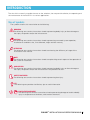
Use of symbols
The symbols used in this manual refer to the following:
WARNING
The following text contains instructions aimed at preventing bodily injury or direct damage to
the crops, the product and/or the infrastructure.
CAUTION
The following text contains instructions aimed at preventing unwanted system operation,
installation or conditions that, if not followed, might void the warranty.
ATTENTION
The following text contains instructions aimed at enhancing the efficiency of usage of the
instructions in the manual.
NOTE
The following text contains instructions aimed at emphasizing certain aspect of the operation of
the system or installation.
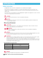
ACID HAZARD
The following text contains instructions aimed at preventing bodily injury or direct damage to
the crops, the product and/or the infrastructure in the presence of acid.
SAFETY FOOTWEAR
The following text contains instructions aimed at preventing foot injury.
TIP
The following text provides clarification, tips or useful information.
PROTECTIVE EQUIPMENT
The following text contains instructions aimed at preventing damage to health or bodily
injury in the presence of fertilizers, acid or other chemicals.
PULSAR TM INSTALLATION AND OPERATION MANUAL 5
INTRODUCTION
Safety instructions
• All applicable safety instructions and regulations must be observed and applied.
• Ensure that the installation is carried out in a manner which prevents leaks from the Pulsar™, the
irrigation lines, the peripherals and the accessories, which may contaminate the environment, soil or
adjacent area.
• The effectiveness of the equipment may be jeopardized or impaired if the equipment is used in a manner
other than that specified by the manufacturer.
WARNING
In an agricultural environment - always wear protective footwear.
CAUTION
When opening or closing any manual valve, always do it gradually, to prevent damage to the
system by water hammer.
When using acid/chemicals
ACID HAZARD
When using acid/chemicals - always observe the manufacturer's safety instructions and use
caution when handling any such acid/chemicals.
WARNING
When handling fertilizers, acid or other chemicals, always use protective equipment,
gloves and goggles.
WARNING
To prevent damage to the environment and to the crop, acids and/or hydrogen peroxide must never
be released to the atmosphere or come in contact with any part of the crop.
ATTENTION
When using acid or hydrogen peroxide, respect the recommended concentrations below in order
to prevent damage to the Pulsar™, the infrastructure, the environment and the crop.
Using concentration levels in excess of the values listed below may cause damage to the Pulsar™,
the infrastructure, the environment and the crop and will void the warranty for the Pulsar™ and/or
any other parts of the irrigation system.
Recommended acid concentrations
Percentage of Acid
Recommended Concentration in Treated Water
Hydrochloric Acid 33%
0.6%
Phosphoric Acid 85%
0.6%
Nitric Acid 60%
0.6%
Sulfuric Acid 65%
0.6%
% is by weight at 21ºC (70ºF)
WARNING
Exceeding the above acid concentrations will damage the Pulsar™
6 PULSAR TM INSTALLATION AND OPERATION MANUAL
INTRODUCTION
If the acid used has a different concentration level from the data included in the table above, adjust the
concentration according to the percentage relative to the concentrations recommended in the table above.
Recommended dosage of hydrogen peroxide
Injection Method / Purpose
Continuous Injection
Selective Injection
Annual maintenance treatment of the irrigation system
Injected Concentration Residual Concentration*
50 ppm
0.5 ppm
50 to 100 ppm
2 to 3 ppm
200 to 500 ppm
8 to 10 ppm
*Measurements must be taken at the point furthest from the injection point.
ATTENTION
The tables above indicates the recommended concentrations of the chemicals and is not a
recommendation, endorsement or otherwise inducement to use the chemicals mentioned above
or any other type of chemical.
WARNING
Substances such as chemicals for pest/disease control might be corrosive and damage the
Pulsar™. When using any substance other than acids and hydrogen peroxide not exceeding
the concentrations in the tables above, always observe the manufacturer's instructions for
corrosiveness. In case of any doubt, consult your Netafim™ representative.
PULSAR TM INSTALLATION AND OPERATION MANUAL 7
DESCRIPTION
The Pulsar™ is a pressure compensated pulsator that distributes relatively small amounts of water over a large
wetted area, maintaining a uniform dispertion. It supplies continuous and uniform irrigation at low flow rates 8/12/15/20 l/hr (2.1/3.2/4.0/5.3 GPH) - using micro-emitters originally designated for higher flow rates.
ATTENTION
The actual flow rate of the Pulsar™ is the flow rate of the flow regulator and not the flow rate of
the emitter head.
Unique self compensating mechanism
The Pulsar's unique self compensating mechanism operates by means of a flow regulator (Pressure
Compensated dripper) installed at its inlet.
The flow regulator consists of:
• a labyrinth which reduces the pressure and stabilizes the flow rate of the irrigation water running through
it.
• a diaphragm which senses the pressure on both its surfaces, on one side - the inlet pressure, on the
other side - the reduced pressure after the irrigation water passage through the labyrinth. The particular
flexibility of the diaphragm determines the pressure difference the flow regulator allows between its
inlet and its outlet.
The combination of the labyrinth and the diaphragm creates a self compensating mechanism which
generates a stable flow rate at its outlet, regardless of the water pressure at its inlet (within the operating
pressure range).
The Pulsar's unique self compensating mechanism amalgamates head losses/gains due to the distance
between the pump and the field, the topography, the main pipes and the accessories, and ensures a
uniform pressure at the inlet of the micro-emitter, regardless of its location in the field.
Operating principle
• The irrigation water enters the Pulsar™ through a flow regulator (Pressure Compensated dripper)
plugged into the lateral.
• The flow regulator allows irrigation water to enter the pulsator tube through the micro-tube at a uniform,
continuous and non fluctuating flow rate.
• An air bag inside the pulsator tube is compressed as water fills the pulsator tube.
• When the pressure inside the pulsator tube reaches the opening level of the anti drain valve - installed at
the outlet of the pulsator tube - it opens and an irrigation pulse starts.
• The emitter head irrigates and the pressure inside the pulsator tube decreases, when it reaches the
closing level of the anti drain valve, the irrigation pulse ends.
• When the anti drain valve closes the pressure inside the pulsator tube starts to build up again for the
next irrigation pulse.
Advantages
• Pressure compensated: Precise and equal amounts of water are delivered over a broad pressure range.
• 100% uniformity of water distribution.
• Unique self compensation mechanism makes it the perfect choice for hillside applications or longer rows.
• Several pulses per minute, according to the selected combination of flow rate and emitter type, ensure
continuous irrigation over a large area for many hours.
• Soil saturation or flooding are avoided even after many hours of irrigation.
• The water supply system, comprising a pump, a filtration system, pipes and fittings is relatively small
and far less expensive to purchase, install and maintain.
• Highly profitable price/performance ratio.
8 PULSAR TM INSTALLATION AND OPERATION MANUAL
DESCRIPTION
• Components are made of high-quality plastic materials resistant to any weather conditions and standard
chemicals and nutrients used in agriculture.
• Energy and water saving.
• Simple, modular parts.
• Easy to install and maintain.
• A wide variety of accessories for a wide range of applications.
• Made by Netafim™.
Specifications
• Pressure-compensation range - 2.5 - 4.0 bar (36 - 58 PSI).
• Optimal required pressure - 3.0 bar (43.5 PSI).
• Recommended filtration: 130 micron (120 mesh).
• UV resistant.
• Chemical resistance to standard chemicals and nutrients used in agriculture (see tables on pages 6-7).
• Inlet connector: barb.
• Several techniques/adapters/fittings are offered for installation in the field (not included),
(see Accessories, page 33).
Applications
• Frost-mitigation
in vineyards,
in trellised crops,
in fruit trees.
• Cooling
• Long shift irrigation
• Humidification
of fruit trees,
of fruit trees,
of the trees area.
of vineyards,
of nurseries
of trellised crops,
and others open field crops.
of nurseries
and others open field crops.
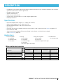
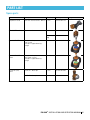
Application
Frost mitigation in vineyards
Frost mitigation in fruit trees
Humidification and/or cooling
Long shift irrigation
Long shift irrigation
Mode
Micro-emitter head selection
StripNet™
UR
+
Required micro-emitter head
GyroNet™ SSR
MistNet™
+
GyroNet™ SR
+
+
+
UD
+
+
PULSAR TM INSTALLATION AND OPERATION MANUAL 9
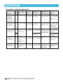
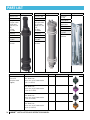
DESCRIPTION
Mode
Key features according to application
Micro-emitter
head
UR StripNet™
Application
• Strip frost
mitigation in
vineyards
• Cooling of
nurseries and
trellised crops
• Humidification UR MistNet™
or Cooling
of trees area
Pressure
range
2.5 - 4.0 bar
(36 - 58 PSI)
Recommended
flow rate
(per unit)
12.0 l/hr
(3.2 GPH)
2.5 - 4.0 bar 8.0 l/hr
(36 - 58 PSI) (2.1 GPH)
UR GyroNet™ SR
Swivel
(Short range)
UD
2.5 - 4.0 bar 8.0 - 12.0 l/hr
(36 - 58 PSI) (2.1 - 3.2 GPH)
• Frost
mitigation
in fruit trees
UR GyroNet™
SSR
Swivel
(Super short
range)
2.5 - 4.0 bar 8.0 - 12.0 l/hr
(36 - 58 PSI) (2.1 - 3.2 GPH)
• Cooling of
fruit trees and
other crops
UR GyroNet™
SR Swivel
(Short range)
2.5 - 4.0 bar 12.0 - 20.0 l/hr
(36 - 58 PSI) (3.2 - 5.3 GPH)
• Irrigation of
fruit trees and
other crops
12.0 l/hr
(3.2 GPH)
* UR = upright, UD = upside down
10 PULSAR TM INSTALLATION AND OPERATION MANUAL
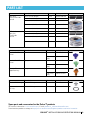
Recommended
distance
between heads
Maximum
5.0 m (16.5 ft)
Wetted
area
Rectangular:
0.5 m (1.65 ft)
wide
5.5 m (18.0 ft)
long
A very fine
mist of water
particles is
emitted into
the atmosphere
One per tree,
Circular:
one per 2 trees 5.0 m (16.5 ft)
or according to
Diameter
the crop needs
Circular:
4.0 m (13.0 ft)
Diameter
One above each Circular:
tree
3.0 m (10.0 ft)
Diameter
One in the
middle of each
tree.
One above
Circular:
each tree or
5.0 m (16.5 ft)
according to the Diameter
crop needs
DESCRIPTION
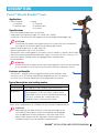
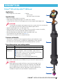
Pulsar™ UR with StripNet™ head
Applications
• Frost-mitigation
in vineyards,
in trellised crops.
Specifications
• Cooling
of vineyards,
of trellised crops,
of nurseries.
• Pressure compensated static micro-emitter.
• Widest pressure regulating range: 2.5-4.0 bar (36 - 58 PSI),
2.5 bar (36 - PSI) minimum working pressure at the compensated dripper inlet.
ATTENTION
To calculate the reqired working pressure of the system take into consideration
the height of the emitters above the distributor pipe (lateral).
• Optimal required pressure - 3.0 bar (43.5 PSI).
• Recommended flow rate: 12 l/hr (3.17 GPH).
• Rectangular water covering pattern: 0.5 meters (1.65 ft) wide by 5.5 meters (18.0 ft) long.
• Maximum recommended distance between heads: 5.0 meters (16.5 ft), (see page 16).
• One active, brown colored nozzle; one plugged, black colored nozzle.
• No moving parts.
ATTENTION
In order to ensure the length of the water covering pattern, make sure that the poles
of the vineyards on which the Pulsars are to be installed, are absolutly vertical.
Features and benefits
• The Pulsar™ - StripNet™ frost-mitigation/cooling system operates using
as little as 10 m 3 /hr hectare (18 GPM/acre) depending on the row spacing less than 70% the water required by full-coverage sprinkler systems.
Typical description* and catalog number
Catalog number 63700-005000
SAP description PLSR URB 012 STR31 ADBLUP 120CM W/O ADP
Product
Pulsar™ UR
components
Flow regulator - 12 l/hr (3.17 GPH) - color: Fuchsia
Micro-tube - 120 cm (4.0 ft) with barb inlet connector
AD valve - with blue pin - medium pressure
StripNet™ head - with one active nozzle
* The description above is of the typical Pulsar™ UR with StripNet™ head.
Many other configurations are available (Call your Netafim™ representative).
ATTENTION
Before placing your order for Pulsars, note that the length of the
micro-tube and the capacity of the flow regulator are compatible
with the application and the conditions in the field. Other microtubes of other lengths and flow regulators of other capacities are
available on request (call your Netafim™ representative).
PULSAR TM INSTALLATION AND OPERATION MANUAL 11
DESCRIPTION
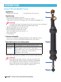
Pulsar™ UR with MistNet™ head
Applications
• Cooling of the trees area.
• Humidification of the trees area.
Specifications
• Pressure compensated micro-emitter.
• Widest pressure regulating range: 2.5-4.0 bar (36 - 58 PSI),
2.5 bar (36 PSI) minimum working pressure at the compensated dripper inlet.
ATTENTION
To calculate the reqired working pressure of the system take into consideration
the height of the emitters above the distributor pipe (lateral).
• Optimal required pressure - 3.0 bar (43.5 PSI).
• Recommended flow rate: 8.0 l/hr (2.1 GPH).
• Recommended distance between heads:
One in the middle of each tree (see page 17).
• Static micro-emitter,
• no moving parts.
Features and benefits
• The Pulsar™ - MistNet™ cooling/humidification system operates using as
little as 10 m 3 /hr hectare (18 GPM/acre) depending on trees spacing.
Typical description* and catalog number
Catalog number 63700-006100
SAP description PLSR URB 008 MST25 ADBLUP 200CM W/O ADP
Product
Pulsar™ UR
components
Flow regulator - 8 l/hr (2.1 GPH) - color: Green
Micro-tube - 200 cm (6.6 ft) with barb inlet connector
AD valve - with blue pin - medium pressure
MistNet™ - brown nozzle
* The description above is of the typical Pulsar™ UR with MistNet™ head.
Many other configurations are available (Call your Netafim™ representative).
ATTENTION
Before placing your order for Pulsars, note that the length of the
micro-tube and the capacity of the flow regulator are compatible
with the application and the conditions in the field. Other microtubes of other lengths and flow regulators of other capacities are
available on request (call your Netafim™ representative).
12 PULSAR TM INSTALLATION AND OPERATION MANUAL
DESCRIPTION
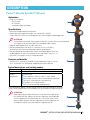
Pulsar™ UR with GyroNet™ SR head
Aplications
• Long shift irrigation
of fruit trees,
of nurseries,
and others open field crops.
Specifications
• Pressure compensated micro-emitter.
• Widest pressure regulating range: 2.5-4.0 bar (36 - 58 PSI),
2.5 bar (36 PSI) minimum working pressure at the compensated dripper inlet.
ATTENTION
To calculate the reqired working pressure of the system take into consideration
the height of the emitters above the distributor pipe (lateral).
• Optimal required pressure - 3.0 bar (43.5 PSI).
• Recommended flow rate: 8 l/hr (2.1 GPH) or 12 l/hr (3.17 GPH),
according to the minimum projected ambient temperature.
• Recommended distance between heads: one above/below each tree
or above/below 2 trees or according to the crop needs (see page 17).
• SR swivel, 5.0 meters (16.5 ft) wetted diameter.
Features and benefits
• The Pulsar™ - GyroNet™ irrigation system operates using as little as
15 m 3 /hr hectare (27 GPM/acre), depending on trees spacing.
Typical description* and catalog number
Catalog number 63700-007100
SAP description PLSR URB 008 GYR9SR ADBCKP 60CM W/O ADP
Product
Pulsar™ UR
components
Flow regulator - 8 l/hr (2.1 GPH) - color: Green
Micro-tube - 60 cm (2.0 ft) with barb inlet connector
AD valve - with black pin - low pressure
GyroNet™ SR - orange nozzle,
blue swivel and orange upper bearing
* The description above is of the typical Pulsar™ UR with GyroNet™ SR head.
Many other configurations are available (Call your Netafim™ representative).
ATTENTION
Before placing your order for Pulsars, note that the length of the
micro-tube and the capacity of the flow regulator are compatible
with the application and the conditions in the field. Other microtubes of other lengths and flow regulators of other capacities are
available on request (call your Netafim™ representative).
PULSAR TM INSTALLATION AND OPERATION MANUAL 13
DESCRIPTION
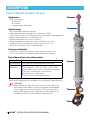
Pulsar™ UD with GyroNet™ SR head
Applications
• Long shift irrigation
of fruit trees,
of nurseries,
and others open field crops.
Specifications
• Pressure compensated micro-emitter.
• Widest pressure regulating range: 2.5-4.0 bar (36 - 58 PSI),
2.5 bar (36 PSI) minimum working pressure at the compensated dripper inlet.
• Optimal required pressure - 3.0 bar (43.5 PSI).
• Recommended flow rate: 12 l/hr (3.17 GPH),
• Recommended distance between heads: one below each tree
or above 2 trees or according to the crop needs (see page 18).
• SR swivel, 4.0 meters (13.0 ft) wetted diameter.
Features and benefits
• The Pulsar™ - GyroNet™ irrigation system operates using as little
as 15 m 3 /hr hectare (27 GPM/acre), depending on trees spacing.
Typical description* and catalog number
Catalog number 63700-010500
SAP description PLSR UDB 012 GYR9SR ADBCKP 60CM GRAY
Product
Pulsar™ UD
components
Flow regulator - 12 l/hr (3.17 GPH) - color: Fuchsia
Micro-tube - 60 cm (2.0 ft) with barb inlet connector
AD valve - with black pin - low pressure
GyroNet™ SR - orange nozzle,
blue swivel and orange upper bearing
* The description above is of the typical Pulsar™ UD with GyroNet™ SR head.
Many other configurations are available (Call your Netafim™ representative).
ATTENTION
Before placing your order for Pulsars, note that the length of the
micro-tube and the capacity of the flow regulator are compatible
with the application and the conditions in the field. Other microtubes of other lengths and flow regulators of other capacities are
available on request (call your Netafim™ representative).
14 PULSAR TM INSTALLATION AND OPERATION MANUAL
DESCRIPTION
Pulsar™ UR with GyroNet™ SSR head
Applications
• Frost mitigation in fruit trees.
Specifications
• Cooling
of fruit trees
and others open field crops.
• Pressure compensated micro-emitter.
• Widest pressure regulating range: 2.5-4.0 bar (36 - 58 PSI),
2.5 bar (36 PSI) minimum working pressure at the compensated dripper inlet.
ATTENTION
To calculate the reqired working pressure of the system take into consideration
the height of the emitters above the distributor pipe (lateral).
• Optimal required pressure - 3.0 bar (43.5 PSI).
• Recommended flow rate: 12l/hr (3.17 GPH), 15l/hr (3.96 GPH) or 20l/hr (5.28 GPH),
according to the minimum projected ambient temperature.
• Recommended distance between heads: one above each tree
or according to the crop needs (see page 17).
• SSR swivel, 3.0 meters (10 ft) wetted diameter.
Features and benefits
• The Pulsar™ - GyroNet™ frost-mitigation/cooling system operates using
as little as 15 m 3 /hr hectare (21 GPM/acre), depending on trees spacing less than 50% the water required by full-coverage sprinkler systems.
Typical description* and catalog number
Catalog number 63700-008000
SAP description PLSR URB 012 GYR9SSR ADBCKP 120CM W/O ADP
Product
Pulsar™ UR
components
Flow regulator - 12l/hr (3.17 GPH) - color: Fuchsia
Micro-tube - 120 cm (4.0 ft) with barb inlet connector
AD valve - with black pin - low pressure
GyroNet™ SSR - orange nozzle,
light green swivel and orange upper bearing
* The description above is of the typical Pulsar™ UR with GyroNet™ SSR head.
Many other configurations are available (Call your Netafim™ representative).
ATTENTION
Before placing your order for Pulsars, note that the length of the
micro-tube and the capacity of the flow regulator are compatible
with the application and the conditions in the field. Other microtubes of other lengths and flow regulators of other capacities are
available on request (call your Netafim™ representative).
PULSAR TM INSTALLATION AND OPERATION MANUAL 15
ON-SITE PREPARATIONS
Typical setups
The Pulsar™ can be set up in various manners to accommodate its many applications.
The most common setups for each application are detailed below.
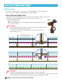
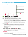
Pulsar™ UR with StripNet™ head
• Rectangular water covering pattern: 0.5 meters (1.65 ft) wide by 5.5 meters (18.0 ft) long.
• Maximum recommended distance between heads: 5.0 meters (16.5 ft).
• The distributor pipe (lateral):
Fig. 1
lies on the ground;
is attached by plastic restraints (bands) or clips to handle to the lower wire
of the trellis system.
ATTENTION
Prior to begining of season, check the system, make sure to adjust the spay
direction exactly along the crop row (trellis).
It is advised to orient the AD valve perpendicular to the direction of the
emitter head (see Fig. 1)
5.0 meters (16.5 ft)
ATTENTION
Maximum recommended distance between heads: 5.0 meters (16.5 feet).
If the distance between the poles along the trellis system is greater than 5 meters (16.5 feet), add
metal or fiberglass rods in between to enable the installation of additional heads.
16 PULSAR TM INSTALLATION AND OPERATION MANUAL
ON-SITE PREPARATIONS
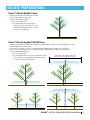
Pulsar™ UR with MistNet™ head
• Recommended distance between heads:
One in the middle of each tree.
• The distributor pipe (lateral):
1) lies on the ground;
2) is attached by plastic restraints
(bands) or clips to handle to a wire
extended at approximately 1 meter
(3 feet) off the ground.
Pulsar™ UR with GyroNet™ SR/SSR head
• Recommended distance between heads: one above/below each tree or above/below 2 trees
or according to the crop needs.
• SR swivel, 5.0 meters (16.5 ft) wetted diameter (depending on height of installation).
• SSR swivel, 3.0 meters (10.0 ft) wetted diameter (depending on height of installation).
• The distributor pipe (lateral):
1) lies on the ground;
SR: diam. 5.0 meters (16.5 ft)
2) is attached by plastic restraints (bands) or clips
SSR: diam. 3.0 meters (10.0 ft)
to handle to a wire extended at approximately
1 meter (3 feet) off the ground.
PULSAR TM INSTALLATION AND OPERATION MANUAL 17
ON-SITE PREPARATIONS
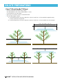
Pulsar™ UD with GyroNet™ SR head
• Recommended distance between heads:
one above/below each tree or above/below 2 trees
or according to the crop needs.
• SR swivel, 4.0 meters (13.0 ft) wetted diameter.
• The distributor pipe (lateral):
1) is attached by plastic restraints (bands) or clips to handle to a wire extended at approximately
1 meter (3 feet) off the ground.
2) is attached by plastic restraints (bands) or clips to handle to a wire extended over the treetops.
Diam. 4.0 meters (13.0 ft)
18 PULSAR TM INSTALLATION AND OPERATION MANUAL
ON-SITE PREPARATIONS
Infrastructure requirements
The water supply system
Install a water supply system of sufficient capacity, including:
A pump
able to supply the pressure and flow rate required for the application.
• Minimum required pressure according to specific micro-emitter head.
• Head losses due to the distance between the pump and the field, the topography, the main pipes
and accessories and the micro-emitter height above distributor pipe (lateral) should be added to the
recommended working pressure when calculating it for the proper operation of the product.
• Required flow rate according to specific micro-emitter head type and quantity.
• TC (total consumption of the system) = The quantity of Pulsars X The flow rate of each Pulsar™.
A filtration system .
• Recommended filtration: 130 micron (120 mesh).
• Filtration method is to be selected based on the kind and concentration of the dirt particles
contained in the water.
• Wherever sand contained in the water exceeds 2ppm, Hydrocyclone filter is to be installed
upstream from the main filter.
• When sand/silt/clay exceeds 100ppm, pre treatment will be applied according to Netafim's expert
team's instructions.
Flow meter , pressure gauges , irrigation valves , lines
and laterals
as required for the application.
• Planning of the system head is beyond the scope of this manual and should be performed by an
expert. For initial guidance consult your Netafim™ representative.
ATTENTION
Since the conditions of the field are different for each installation, the installer should prepare the
appropriate infrastructure as planned by an expert according to the actual conditions in the field
(consult your Netafim™ representative).
PULSAR TM INSTALLATION AND OPERATION MANUAL 19
ON-SITE PREPARATIONS
CAUTION
During the preparation of the infrastructure and the installation of the Pulsars, make sure the
ends of the pipes and the laterals are never left open, to prevent dirt, insects or rodents from
penetrating them.
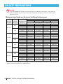
Maximum lateral length on a flat terrain* at different inlet pressures
Flow rate
Lateral
l/hr (GPH) Diam./class
16/4
8.0 (2.1)
20/4
16/4
12.0 (3.2)
20/4
16/4
15.0 (4.0)
20/4
16/4
20.0 (5.3)
20/4
Inlet pressure
bar (PSI)
3.0 (43.5)
3.5 (51.0)
4.0 (58.0)
3.0 (43.5)
3.5 (51.0)
4.0 (58.0)
3.0 (43.5)
3.5 (51.0)
4.0 (58.0)
3.0 (43.5)
3.5 (51.0)
4.0 (58.0)
3.0 (43.5)
3.5 (51.0)
4.0 (58.0)
3.0 (43.5)
3.5 (51.0)
4.0 (58.0)
3.0 (43.5)
3.5 (51.0)
4.0 (58.0)
3.0 (43.5)
3.5 (51.0)
4.0 (58.0)
Distance between emitters - meters (feet)
3.0 (10.0)
5.0 (16.5)
7.0 (23.0)
9.0 (29.5)
Maximum lateral length - meters (feet)
159 (522)
225 (738)
280 (919)
333 (1093)
204 (669)
285 (935)
357 (1171)
423 (1388)
237 (778)
330 (1083)
413 (1355)
486 (1594)
249 (817)
345 (1132)
434 (1424)
504 (1654)
318 (1043)
445 (1460)
553 (1814)
648 (2126)
369 (1211)
515 (1690)
637 (2090)
747 (2451)
123 (404)
175 (574)
217 (712)
261 (856)
159 (522)
225 (738)
280 (919)
324 (1063)
183 (600)
255 (837)
322 (1056)
378 (1240)
192 (630)
270 (886)
336 (1102)
396 (1299)
246 (807)
345 (738)
427 (1401)
504 (1654)
285 (935)
395 (1132)
497 (1631)
585 (1919)
108 (354)
150 (492)
189 (620)
225 (738)
138 (453)
195 (640)
245 (804)
288 (945)
159 (522)
225 (738)
280 (919)
333 (1093)
168 (551)
235 (771)
294 (965)
342 (1122)
213 (699)
300 (984)
371 (1217)
441 (1447)
249 (817)
345 (1132)
427 (1401)
504 (1654)
90 (295)
125 (410)
161 (528)
189 (620)
114 (374)
160 (525)
203 (666)
243 (797)
132 (433)
185 (607)
231 (758)
279 (915)
141 (463)
195 (640)
245 (804)
288 (945)
180 (591)
250 (820)
308 (1010)
369 (1211)
207 (679)
290 (951)
357 (1171)
423 (1388)
*The maximum lateral length differs acording to variations in the elevation of the terrain. In case the terrain
is not flat, consult your Netafim™ representative.
20 PULSAR TM INSTALLATION AND OPERATION MANUAL
INSTALLATION
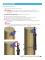
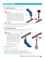
Attaching the Pulsar™
The Pulsar™ tube can be attached in four manners:
ATTENTION
In UR applications, the length of the Pulsar's micro-tube should allow some tolerance.
Attach the Pulsar™ at a distance from the lateral that allows its micro-tube to reach the lateral
without tension.
To wooden poles using clamps (catalog number: 64420-003100)
Fasten the clamp to the wooden pole using 2 wood screws.
A Insert one of the screws into a buttonhole and use it to vertically adjust the clamp.
Press the neck of the Pulsar™ tube into the clamp - a "CLICK" is heard.
Couple the Pulsar™ tube to the wooden pole using a plastic restraint (band).
If the circumference of the wooden pole is bigger than 25 cm (10") use 2 plastic restraints (bands)
connected together.
CAUTION
Make sure to use UV protected plastic restraints (bands) to fit the Pulsar™ tube to the stake/pole
(for recommended product and catalog number see Part List, page 35).
A
CLICK!
PULSAR TM INSTALLATION AND OPERATION MANUAL 21
INSTALLATION
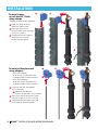
CLICK!
To metal stakes up to 5 mm (0.2") thick,
using clamps
(catalog number: 64420-003010)
Slide the clamp onto the
top of the metal stake.
Press the neck of the
Pulsar™ tube into the clamp a "CLICK" is heard.
Couple the Pulsar™ tube to
the metal stake using a
plastic restraint (band).
CLICK!
To metal or fiberglass rods
using adapters
Blue color adapter for 6 mm (0.24") diameter rod catalog number: 63520-005950
Black color adapter for 8 mm (0.31") diameter rod catalog number: 63520-005970
A
Insert the rod into the adapter
(use a hammer).
A Observe the aperture make sure the rod is fully inserted.
Press the neck of the Pulsar™ tube
into the clamp - a "CLICK" is heard.
Couple the Pulsar™ tube to the rod
using a plastic restraint (band).
22 PULSAR TM INSTALLATION AND OPERATION MANUAL
INSTALLATION
Connecting the Pulsar™ to the lateral
For all the UR applications
Punch a hole in the lateral using a 3 mm punching tool.
CAUTION
After completion of the infrastructure - water
supply system, lines and laterals, and punching
the holes in the laterals, before the installation of
the Pulsators, open the ends of the laterals and
thoroughly rinse the infrastructure by running water
through it in order to wash away any residues
(chips, shavings, sawdust) due to the setup work.
After rinsing the infrastructure, close the ends of
the laterals.
CLICK!
ATTENTION
In UR applications, the length of the Pulsar's micro-tube should allow some tolerance.
The Pulsar's micro-tube must reach the lateral without tension.
Plug the flow regulator's barb into the hole in the lateral.
For the UD application only
The Pulsar™ is hanging from the distributor pipe (lateral), not attached to a clamp.
Punch a hole on the underside of the lateral using a punching tool.
CAUTION
After completion of the infrastructure water supply system, lines and laterals,
and punching the holes in the laterals,
before the installation of the Pulsators,
open the ends of the laterals and
thoroughly rinse the infrastructure
by running water through it in order
to wash away any residues (chips,
shavings, sawdust) due to the setup
work.
After rinsing the infrastructure, close
the ends of the laterals.
CLICK!
Plug the flow regulator's barb into the
hole in the lateral.
Inspection after installation
1) Operate the system until it reaches the head pressure as planned.
2) See that the flow rate indicated by the water meter is as planned.
3) Perform a visual sample inspection in the field. See that the Pulsars are pulsating.
4) If a Pulsar™ is not pulsating or is leaking, refer to Troubleshooting, page 27.
PULSAR TM INSTALLATION AND OPERATION MANUAL 23
OPERATION AND MANTENANCE
Current operation according to application
Frost mitigation
Operate the system according to the temperature, the relative humidity and the phenological state of the
crop.
Irrigate continuously until the end of the frost event (until all the ice accumulated on the crop completely
melted).
Recomended precipitation rate (PR) > 3 mm/hr (0.12"/hr)
Long shift irrigation
Irrigate at a precipitation rate (PR) of at least 1 mm/hr (or as needed) and make sure the precipitation rate
during all the irrigation shift is higher than the evaporation rate (for clarifications call Netafim™).
The duration of irrigation is calculated on the basis of the daily return required by the crop (based on the
phenological stage of the crop and the evapotranspiration), divided by the calculated precipitation rate.
Humidification and cooling
Misting (Using the Pulsar™ UR with the MistNet™ head) - A very fine mist of water particles is emitted,
absorbing the heat energy from the atmospher while evaporating (The lower the relative humidity, the
higher the cooling efficiency).
Contact cooling (Using the Pulsar™ UR or UD with the GyroNet™ SR or SSR head, or the Pulsar™ UR
with the StripNet™ head) - Drops of water are in contact with the crop. The temperature difference
between the drops and the crop is equalized by means of the drops absorbing the heat from the crop and
pouring from its surface.
Activation and operating duration of the system according to the temperature, the relative humidity and
the effect the agriculturist wants to achieve in accordance with the phenological stage of the crop (consult
an expert/agronomist).
TIP
It is possible to use cooling to extend the hours of low temperature per day (before sunset and
after sunrise) in areas and seasons where the low temperature per day is borderline and not
sufficient to meet the conditions required for the crop according to the recommendations of the
expert/agronomist.
Calculating the precipitation rate (PR)
Calculation of the wetted area (WA):
For GyroNet™ applications (round wetted area)
Square the radius (half the diameter) of the wetted area and then multiply by 3.14 (π).
Wetted area = π x r²
For StripNet™ applications (rectangular wetted area)
Multiply the length (L) of the wetted area by its width (W).
Wetted area = L x W
Calculation of the precipitation rate (PR):
Precipitation rate (PR) =
the flow rate divided by the wetted area
Flow rate
Precipitation rate (PR) =
wetted area
Units
Length:
Area:
Flow rate:
Precipitation
rate (PR):
24 PULSAR TM INSTALLATION AND OPERATION MANUAL
Metric
Meter (m)
Square meter (m²)
l/hr
US
Feet (ft)
Square feet (ft²)
GPH
mm/hr
Inch/hour ("/hr)
OPERATION AND MANTENANCE
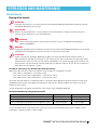
Maintenance
Rinsing of the laterals
ATTENTION
Rinsing of the laterals is an essential action and should be abidingly performed in order to maintain
the proper operation of the system.
ACID HAZARD
When using acid/chemicals - always observe the manufacturer's safety instructions and use
caution when handling any such acid/chemicals.
WARNING
When handling fertilizers, acid or other chemicals, always use protective equipment,
gloves and goggles.
WARNING
To prevent damage to the environment and to the crop, acids and hydrogen peroxide must never be
released to the atmospher or come in contact with any part of the crop.
ATTENTION
When using acid or hydrogen peroxide, respect the recommended concentrations below in
order to prevent damage to the Pulsar™, the infrastructure, the environment and the crop. Using
concentrations levels in excess of the values listed below may cause damage to the Pulsar™, the
infrastructure, the environment and the crop and will void the warranty for the Pulsar™ and/or any
other parts of the irrigation system.
In order to wash away accumulated dirt from the laterals
Open the end of the line, allow the irrigation water to flow for a couple of minutes:
If the water is transparent - rinse once a year
If the color of the water is light brown - rinse once a month
If the color of the water is dark brown - rinse once a week
To ensure that the capacity of the pump allows a sufficient flow speed for efficient removal of dirt from
the piping while rinsing, never open simultanuously more than 5 laterals (repeat this actions for all the
laterals in the system).
In case of presence of organic substances in the water, inject hydrogen peroxide.
Recommended dosage of hydrogen peroxide
Injection Method / Purpose
Continuous Injection
Selective Injection
Annual maintenance treatment of the irrigation system
Injected Concentration Residual Concentration*
50 ppm
0.5 ppm
50 to 100 ppm
2 to 3 ppm
200 to 500 ppm
8 to 10 ppm
*Measurements must be taken at the point furthest from the injection point.
In case of potential for scale formation in the water, and to avoid sedimentation of low solubility salts/
carbonates, injection of acid is recomended.
PULSAR TM INSTALLATION AND OPERATION MANUAL 25
OPERATION AND MANTENANCE
Recommended acid concentrations
Percentage of Acid
Recommended Concentration in Treated Water
Hydrochloric Acid 33%
0.6%
Phosphoric Acid 85%
0.6%
Nitric Acid 60%
0.6%
Sulfuric Acid 65%
0.6%
% is by weight at 21ºC (70ºF)
WARNING
Exceeding the above acid concentrations will damage the Pulsar™
If the acid used has a different concentration level from the data included in the table above, adjust the
concentration according to the percentage relative to the concentrations recommended in the table above.
WARNING
The amount of chemicals to be injected should be according to the amount of pollution in the pipes
(for further instructions see Preventive maintenance of dripping systems on appendix 1, Further
reading, page 37)
WARNING
To prevent damage to the environment and to the crop, acids and hydrogen peroxide must never be
released to the atmospher or come in contact with any part of the crop.
While rinsing the system with those substanses, make sure that the pressure in the system does
not exceed 1.5 bar (22 PSI) to ensure that the anti-drain valves (AD) of the Pulsars do not open.
After completion of the rinsing process, make sure to reset the system to its usual operating
pressure.
After injecting acids or hydrogen peroxide, operate the system for at least an hour with clean water.
Periodic inspection
Perform a visual inspection once every 1 million pulses while the system is active in order to detect natural
wear of the Pulsar's components. See that the pulse rate is uniform, if it is not, see Troubleshooting, page 27.
26 PULSAR TM INSTALLATION AND OPERATION MANUAL
TROUBLESHOOTING
A thorough consideration of all the possible malfunctions of the Pulsars system and infrastructure is
beyond the scope of this manual. If you experience a malfunction that is not referred to in this chapter,
consult your Netafim™ representative.
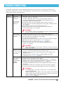
Malfunction Possible causes Actions
1) While the system is operating, disconnect the micro-emitter from the
Water is
The microanti-drain valve (AD) and check:
not emitted. emitter's head
If water is pulsating from the outlet of the anti-drain valve (AD) is blocked.
Check for clogging of the micro-emitter nozzle (proceed to step 2).
2) Disassemble the micro-emitter head.
The anti-drain
3) Thoroughly clean the micro-emitter nozzle with pressurized air.
valve (AD) is
4)
Visually check for remaining clogging and clean again with pressurized
defective.
air if needed.
5) Reassemble and reinstall the micro-emitter head.
6) Activate the Pulsar™. If the malfunction persists, replace the
micro-emitter head with a new one.
ATTENTION
For GyroNet™ - Make sure to replace the micro-emitter head with
one with a swivel of the same color.
1) Check that the pressure on the lateral near the flow regulator is
The anti-drain
valve (AD) does according to the recommendation + the height of the anti-drain valve (AD)
above the lateral (use a Needle Pressure Gauge).
not open.
If it is not - restore the pressure.
If the pressure is correct and the anti-drain valve (AD) still does not open Replace the anti-drain valve (AD) (see CAUTION, page 29).
1) Remove the faulty anti-drain valve (see Fig. 2, page 30).
2) Install a new anti-drain valve. Mind the protruding placemarks
(see Fig. 5, page 30).
There is a
breach, a tear
or a hole in the
micro-tube.
The inlet of the
flow regulator
(pressure
compensated
dripper) is
blocked.
ATTENTION
Make sure to replace the anti-drain valve (AD) with one with a pin
of the same color.
Replace the faulty section of the micro-tube.
1) Cut the micro-tube on both sides of the faulty section.
2) Prepare a new section of the micro-tube of the same length as the
deleted section.
3) Connect the new section using two coupling barb micro-tube
connectors (see Accessories, page 35).
Replace the flow regulator (pressure compensated dripper).
1) Unplug the flow regulator from the lateral.
2) Plug the hole in the lateral using a dripline plug (see Fig. 1, page 30).
3) Punch a new hole in the lateral at a distance of at least 2 cm (1") from
the plugged one, using a punching tool (see Fig. 4, page 30).
4) Insert the colored barb of the new flow regulator into the new hole in
the lateral.
5) Cut the micro-tube a few milimeters from the faulty flow regulator.
6) Connect the micro-tube to the black barb of the new flow regulator.
ATTENTION
In UR applications, the length of the Pulsar's micro-tube should
allow some tolerance.
If after cutting the micro-tube, it is too short to allow it to reach the
lateral without tension, add a section of micro-tube and connect it
using a coupling barb micro-tube connector
(see Accessories, page 35).
PULSAR TM INSTALLATION AND OPERATION MANUAL 27
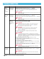
TROUBLESHOOTING
Malfunction
Water
emitted
continuously,
not
pulsating.
Possible causes
The anti-drain
valve (AD) is
out of order.
Pulsating
rate is not
regular.
The anti-drain
valve (AD) is
out of order.
Actions
Replace the anti-drain valve (AD) (see CAUTION, page29).
1) Remove the faulty anti-drain valve (see Fig. 4, page 30).
2) Install a new anti-drain valve. Mind the protruding placemarks
(see Fig. 5, page 30).
ATTENTION
Make sure to replace the anti-drain valve (AD) with one with a pin
of the same color.
There is a
puncture or
a tear in the
pulsator's air
bag.
Replace the anti-drain valve (AD) (see CAUTION, page29).
1) Remove the faulty anti-drain valve (see Fig. 4, page 30).
2) Install a new anti-drain valve. Mind the placemarks (see Fig. 3, page 30).
ATTENTION
Make sure to replace the anti-drain valve (AD) with one with a pin
of the same color.
Check the integrity of the pulsator's air bag.
1) Disconnect the Pulsar™ from the adapter.
ATTENTION
To prevent damage to the adapter - do not pull the Pulsar™.
Rotate the Pulsar™ to disconnect it (see Fig. 3, page 30).
2) Unscrew the cap from of the pulsator's tube.
ATTENTION
Unscrew the cap from the pulsator's tube by rotating the
pulsator's tube and avoiding twisting the micro-tube
(see Fig. 8, page 30).
3) Manually pull the pulsator's air bag out of the pulsator's tube
(see Fig. 9, page 30).
ATTENTION
To avoid damaging the pulsator's air bag, do not use tools to
manipulate it. However, if it is impossible to pull the air bag out of
the pulsator's tube by hand, gently use tweezers and mind not to
puncture or scratch the air bag.
4) Manually apply pressure to the air bag and check if it is flat.
5) If any doubt, fill a recipient with water.
6) Dip the air bag in the water, manually apply pressure to the air bag
and check for air bubbles.
7) If the pulsator's air bag is damaged, replace it.
8) Insert the air bag into the pulsator's tube and push it in until it stops
(see Fig. 10, page 30).
9) Screw the pulsator's cap a full circle until the tooth on the thread snaps
into the slot in the pulsator's tube (see Fig. 6, page 30).
ATTENTION
Screw the pulsator's cap by rotating the pulsator's tube and
avoiding twisting the micro-tube.
GyroNet™
swivel does
not rotate.
The swivel is
worn.
Replace the swivel.
1) Remove the GyroNet™ head and disassemble it (see Fig. 7, page 30).
2) Replace the swivel.
ATTENTION
Make sure to replace the swivel with one of the same color.
3) Reinstall the GyroNet™ head.
28 PULSAR TM INSTALLATION AND OPERATION MANUAL
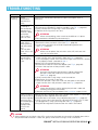
TROUBLESHOOTING
Malfunction Possible causes
The Pulsar™ Loose
connections
is leaking
between the
parts.
The MistNet™
is leaking at
the connection
between the
MistNet's body
and nozzle.
The O-ring is
worn or riven.
The anti-drain
valve (AD) is
leaking from its
cap (around the
pin).
The anti-drain
valve (AD) is out
of order.
The O-ring of
the pulsator's
cap is worn or
riven.
Actions
Check all the connections between the parts and tighten them if
necessary.
Replace the O-ring of the MistNet™.
1) Disconnect the MistNet™ and disassemble it (see Fig. 11, page 30).
2) Gently remove the O-ring using a small screwdriver
3) Replace the O-ring with a new one
ATTENTION
When reassembling, make sure that the diffuser is in place.
4) Reassemble the MistNet™ and reconnect it
Replace the anti-drain valve (AD) (see CAUTION below).
1) Remove the faulty anti-drain valve (see Fig. 2, page 30).
2) Install a new anti-drain valve. Mind the protruding placemarks
(see Fig. 5, page 30).
ATTENTION
Make sure to replace the anti-drain valve (AD) with one with
a pin of the same color
1) Check if the pulsator's cap is properly closed, the tooth on the thread
snaps into the slot in the pulsator's tube (see Fig. 6, page 30).
If it is not properly closed - close it and check again if the Pulsar™ is leaking.
If it is properly closed - proceed to step 2.
Replace the O-ring of the pulsator's cap.
1) Disconnect the Pulsar™ from the adapter (see Fig. 3, page 30).
2) Unscrew the cap from of the pulsator's tube.
ATTENTION
Unscrew the cap from the pulsator's tube by rotating the
pulsator's tube and avoiding twisting the micro-tube
(see Fig. 8, page 30).
3) Gently remove the O-ring using a small screwdriver.
4) Replace the O-ring with a new one.
5) Screw the pulsator's cap a full circle until the tooth on the thread
snaps into the slot in the pulsator's tube (see Fig. 6, page 30).
ATTENTION
Screw the pulsator's cap by rotating the pulsator's tube and
avoiding twisting the micro-tube.
6) Reattach the Pulsar™ to the adapter (see Installation, pages 21-23).
There is a leak at Relocate the flow regulator (pressure compensated dripper) in a new hole.
the connection of 1) Unplug the flow regulator from the lateral.
the flow regulator 2) Plug the hole in the lateral using a dripline plug (see Fig. 1, page 30).
(pressure com3) Punch a new hole in the lateral at a distance of at least 2 cm (1") from
pensated dripper)
the plugged one, using a punching tool (see Fig. 4, page 30).
to the lateral.
4) Plug the flow regulator's barb into the new hole in the lateral.
Improper hole
punch in the
lateral.
CAUTION
When replacing an anti-drain valve (AD), make sure that there are no remains of broken parts left in
the pulsator-tube connector. If there are, gently remove them using a small screwdriver.
PULSAR TM INSTALLATION AND OPERATION MANUAL 29
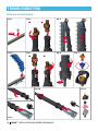
TROUBLESHOOTING
Reference illustrations
Fig. 3
Fig. 2
Fig. 1
B
A
CLICK!
Fig. 6
Fig. 5
Fig. 4
B
A
n.
Mi
m
2c
Fig. 7
)
(1"
CLICK!
Fig. 10
Fig. 8
Fig. 9
30 PULSAR TM INSTALLATION AND OPERATION MANUAL
Fig. 11
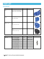
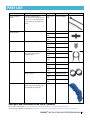
PART LIST
Spare parts
Name
StripNet™ head
Description
Quantity
With one active nozzle - brown 1 unit
Catalog number
64420-002770
MistNet™ head
Brown nozzle
1 unit
63100-040000
100 units/
bag
63100-040020
GyroNet™ SR head Orange nozzle,
blue swivel,
Everspin™ upper bearing orange
1 unit
64000-030507
GyroNet™ SSR
head
Orange nozzle,
light green swivel,
Everspin™ upper bearing orange
1 unit
64000-030509
Anti drain (AD)
valve
PLSR AD - black pin
1 unit
63700-001000
PLSR AD - blue pin
1 unit
63700-001020
Image
PULSAR TM INSTALLATION AND OPERATION MANUAL 31
PART LIST
Name
Pulsar™ UR
Description
Upright
pulsator tube.
PLSR tube
barb assy for
UR,
Air bag
included
Quantity
1 unit
Catalog
number
63700001400
Name
Flow regulator
(Pressure
Compensated
dripper)
Image
Name
Image
Pulsar™ UD
Description
Upside down
pulsator tube.
PLSR tube
barb assy for
UD,
Air bag
included
Quantity
1 unit
Catalog
number
63700001500
Name
Pulsar™
air bag
Description
for all
application
Quantity
1 unit
Catalog
number
63720002000
Description
Green.
With barb inlet
and 4 mm (0.16") barb outlet.
8 l/hr (2.1 GPH)
Quantity Catalog number
1 unit
21500-002300
Fuchsia.
With barb inlet
and 4 mm (0.16") barb outlet.
12 l/hr (3.17 GPH)
1 unit
21500-002400
Black.
With barb inlet
and 4 mm (0.16") barb outlet.
15 l/hr (4.0 GPH)
1 unit
21500-003020
Orange.
With barb inlet
and 4 mm (0.16") barb outlet.
20 l/hr (5.3 GPH)
1 unit
21620-001350
32 PULSAR TM INSTALLATION AND OPERATION MANUAL
Image
Image
PART LIST
Name
SPE 4/6.5
black micro-tube
For UR
SPE 4/6.5
light gray
micro-tube
For UD
Name
GyroNet™ SR
swivel
GyroNet™ SSR
swivel
Everspin™
upper bearing -
Description
60 cm (2.0 ft) length
Quantity Catalog number
1 unit
40000-006160
120 cm (4.0 ft) length
1 unit
40000-006260
100 meter (328 ft) coil
1 coil
40000-006510
200 meter (656 ft) coil
1 coil
40000-006560
500 meter (1640 ft) coil
1 coil
40000-006580
60 cm (2.0 ft) length
120 cm (4.0 ft) length
1 unit
1 unit
40000-005120
40000-005280
200 meter (656 ft) coil
1 coil
40000-004850
500 meter (1640 ft) coil
1 coil
40000-004950
Description
blue
Quantity
1 unit
Catalog number
63520-005200
63520-005220
light green
100 units/
bag
1 unit
63520-003400
orange
100 units/
bag
1 unit
100 units/
bag
63520-011425
Image
Image
63520-005320
63520-011400
Name
MistNet™ "O" ring
Description
Rubber "O" ring
Quantity
1 unit
Catalog number
63120-001000
Pulsator tube
"O" ring
Rubber "O" ring
1 unit
63720-001700
Image
Spare parts and accessories for the Pulsar™ products
For further information: www.netafim.com, E-mail: products_solutions@netafim.com
Download the product catalogs at http://www.netafim.com/irrigation-products-technical-materials
PULSAR TM INSTALLATION AND OPERATION MANUAL 33
PART LIST
Accessories
Name
Clamp for wood
poles
Description
Quantity
Clamp adapter,
1 unit
connecting to wood poles by 2
wood screws (not included).
Catalog number
64420-003100
Clamp for metal
stakes
Clamp adapter,
for 2.5 to 5.0 mm (0.1 to 0.2")
thick metal stakes.
1 unit
64420-003010
Adapter to metal/
fiberglass rods
Adapter
Blue.
For 6 mm (0.24") rod.
1 unit
63520-005950
Adapter
Black.
For 8 mm (0.31") rod.
1 unit
63520-005970
Description
6 mm (0.24") diameter,
60 cm (2.0 ft) length.
6 mm (0.24") diameter,
100 cm (3.3 ft) length.
6 mm (0.24") diameter,
120 cm (3.9 ft) length.
8 mm (0.31") diameter,
60 cm (2.0 ft) length.
8 mm (0.31") diameter,
100 cm (3.3 ft) length.
8 mm (0.31") diameter,
120 cm (3.9 ft) length.
Quantity
1 unit
Catalog number
65080-001000
1 unit
65080-001100
1 unit
65080-001200
1 unit
65080-001500
1 unit
65080-001600
1 unit
65080-001700
Name
Metal rod
34 PULSAR TM INSTALLATION AND OPERATION MANUAL
Image
Image
PART LIST
Name
Plastic restraint
(band)
Description
Black band 380*4.8 UV.
For correct installation of the
Pulsar™ it is recommended
to use special UV protected
bands.
Quantity
100 units/
bag
Catalog number
63720-001800
Micro-tube
coupling barb
4/6.5
1 unit
50 units/
bag
100 units/
bag
1 unit
50 units/
bag
100 units/
bag
1 unit
50 units/
bag
100 units/
bag
63520-006000
63520-006010
Plug 5 mm
To plug holes in PE pipes.
Smart clip to handle 16 mm (0.63") OD tube.
For correct handling of
irrigation pipe.
"8" line end
16 mm (0.63").
20 mm (0.79").
Punching tool
A 3 mm reliable and strong
plastic punch designed with a
comfortable grip handle.
Image
63520-006020
32000-001100
32000-001110
32000-001120
32000-003400
32000-003420
32000-0034XX
1 unit
50 units/
bag
32500-013000
32500-013020
100 units/
bag
32500-013030
1 unit
50 units/
bag
32500-014400
32500-014420
100 units/
bag
32500-014430
1 unit
45000-001200
Spare parts and accessories for the Pulsar™ products
For further information: www.netafim.com, E-mail: products_solutions@netafim.com
Download the product catalogs at http://www.netafim.com/irrigation-products-technical-materials
PULSAR TM INSTALLATION AND OPERATION MANUAL 35
WARRANTY
Netafim™ warrants all the components of the Pulsar™ to be free of substantial defects in material and
workmanship for a period of no more than 1 (one) year from the date of purchase.
If a defect is discovered during the applicable warranty period, Netafim™ will repair or replace, at its
discretion, the product or the defective part.
This warranty does not extend to repairs, adjustments or replacements of a Pulsar™ or part
resulting from misuse, negligence, alteration, force majeure, lightning, improper installation or improper
maintenance, including the misapplication of acid/chemicals or any other maltreatment of the Pulsar™ or
any part of the irrigation systems.
If a defect arises in your Netafim™ product during the warranty period, contact your Netafim™ supplier.
Limited warranty
This warranty is subject to the terms and conditions contained in Netafim's official warranty statement, as
such is in force from time to time.
For the full text of Netafim's official warranty statement, go to:
http://www.netafim.com/irrigation-products-technical-materials
36 PULSAR TM INSTALLATION AND OPERATION MANUAL
APPENDIX 1
Further reading
This appendix provides Pulsar™ users with links to recommended complementary documents discussing
related subjects at length.
Download them at http://www.netafim.com/irrigation-products-technical-materials
Guidelines for Irrigation Systems Maintenance
The implementation of a simple yet strict maintenance program for drip irrigation systems will achieve the
following:
• Keep the system operating at peak performance
• Increase the system's work life expectancy.
This manual will guide you in determining the correct procedure and its implementation. The best way to
determine if your maintenance program is effective is to constantly monitor and record the flow rate and
pressures in the system.
Maintenance is divided in two categories: PREVENTIVE and CORRECTIVE.
Avoiding Frost Damage
Frost mitigation constitutes an integral component of deciduous plant cultivation in numerous regions
throughout the world. This guide provides fundamental data and explanations for dealing with frost and
frost mitigation. By means of professional articles, the guide presents and explains the principles and basic
terms of the phenomenon and sets out possible solutions. Numerous professional articles and data banks
provide information and explain how to deal with the subject. We at Netafim™ have selected only a small
part of the existing material, and will continue to publish more articles that will expand our knowledge in
this subject.
Guide book - Cooling
How to avoid crops and animals from being affected by high temperatures.
There are some areas of the world in which the agricultural crops require assistance and cooling, especially
during hot days, in order to prevent them from being subjected to unnecessary stress. In other areas, the
color of fruit can be improved by cooling the trees during the correct time period.
It is possible to extend the shelf life of some types of fruit by cooling them while they are still on the trees.
And by using correct and supervised cooling, we can increase the flower fruit set during periods of very
hot weather. In other regions, we can aid and improve the yield of fruit crops by cooling during the autumn
and winter months, and then adding cold units to the same trees or cooling the same crops at the end of
the winter months in order to cause early blossoming.
Dripperlines, drippers & other emitters - Product catalog
The following catalog is an aid material to enable to find basic data on each of the drip products at hands
reach.
In each section you will find:
1. Main applications of the item displayed.
2. Features and benefits.
3. Technical data of drippers and dripperlines.
4. A table of all active catalog numbers.
5. Basic packaging data.
PULSAR TM INSTALLATION AND OPERATION MANUAL 37
APPENDIX 1
Micro sprinklers, micro emitters & sprinklers - Product catalog
The following catalog is an aid material to enable to find basic data on each of the products at hands reach.
1. Pressure compensated Micro-sprinklers and Micro-emitters.
2. Micro-sprinklers and Micro-emitters.
3. Micro-sprinklers and Micro-emitters Up-right stands complementary accessories.
4. Micro-emitters for nurseries and pot irrigation.
5. Micro-sprinklers and Micro-emitters for protected crops.
6. Micro-sprinklers and Micro-emitters Upside-down stands complementary accessories.
7. Sprinklers and Midi-sprinklers.
8. Sprinklers stands complementary accessories.
9. Micro-tubes and tubes, complementary accessories.
10. Tools.
38 PULSAR TM INSTALLATION AND OPERATION MANUAL
GROW MORE WITH LESS
WWW.NETAFIM.COM