1
DRIP IRRIGATION
HANDBOOK
UNDERSTANDING THE BASICS
V 001.01 - 2014
© COPYRIGHT 2013, NETAFIM™
NO PART OF THIS PUBLICATION MAY BE REPRODUCED, STORED IN AN AUTOMATED DATA FILE OR MADE PUBLIC IN
ANY FORM OR BY ANY MEANS, WHETHER ELECTRONIC, MECHANICAL, BY PHOTOCOPYING, RECORDING OR IN ANY
OTHER MANNER WITHOUT PRIOR WRITTEN PERMISSION OF NETAFIM™.
THIS DOCUMENT IS PRESENTED WITH THE EXCLUSIVE AIM OF NOTIFYING SELECTED POTENTIAL CLIENTS REGARDING
THE NETAFIM™ DRIP IRRIGATION SYSTEM. RECEIPT OR THE POSSESSION OF THIS DOCUMENT DOES NOT IMPLY
RIGHTS AND THE CONTENTS SHOULD BE VIEWED AS A PROPOSAL ONLY. THIS DOCUMENT IS NEITHER ISSUED AS A
GUARANTEE, NOR IS IT LEGALLY BINDING.
NETAFIM™ ENDEAVORS TO PROVIDE QUALITY, ACCURATE AND DETAILED INFORMATION. NEVERTHELESS, NETAFIM™
CANNOT ACCEPT ANY RESPONSIBILITY FOR RELIANCE ON THE INFORMATION PROVIDED, AND THE USER IS ADVISED
TO INDEPENDENTLY OBTAIN THE PROFESSIONAL ADVICE OF NETAFIM™ AND/OR ITS AUTHORIZED REPRESENTATIVES.
THERE IS NO UNDERTAKING BY NETAFIM™ THAT THE PROVIDED INFORMATION OR ANY PART THEREOF IS ACCURATE,
COMPLETE OR UP TO DATE.
MENTION OF THIRD-PARTY PRODUCTS IS FOR INFORMATIONAL PURPOSES ONLY AND CONSTITUTES NEITHER AN
ENDORSEMENT NOR A RECOMMENDATION. NETAFIM™ DOES NOT ASSUME ANY RESPONSIBILITY WITH RESPECT TO
THE USE OR THE PROVISIONS OF SUCH PRODUCTS.
NETAFIM™ WILL NOT ACCEPT RESPONSIBILITY FOR DAMAGE OR LOSS THAT MAY RESULT FROM THE USE OF
NETAFIM'S PRODUCTS OR THE USE OF THIS DOCUMENT.
NETAFIM™ RESERVES THE RIGHT TO MAKE CHANGES AND IMPROVEMENTS TO ITS PRODUCTS AND/OR THE
ASSOCIATED DOCUMENTATION WITHOUT PRIOR NOTICE.
FOREIGN LANGUAGES
In the event that you are reading this manual in a language other than the English language, you
acknowledge and agree that the English language version shall prevail in case of inconsistency or
contradiction in interpretation or translation.
CONTENTS
Introduction
4
5
6
Aim of this document
Safety instructions
Use of symbols in this document
Drip irrigation system overview
7
An overview of the drip irrigation system components, their functions and properties:
Structure of a drip irrigation system; Water source; Pumps & pumping stations; Filtration;
Main, sub-main, distribution pipes and fittings; Water meters and pressure gauges; Valves;
Dosing unit; Dripperlines (laterals); Connectors; End of dripperlines; Sensors; Controller;
Accessories and add-ons; Agro-machinery.
Drip irrigation management and operation
47
Guidelines and useful tips for the proper management and operation of a drip irrigation system:
Irrigation; Nutrigation™; Nutrigation™ via a drip irrigation system; Chemigation;
Dripperline insertion or laying.
Drip irrigation system maintenance
65
Guidelines and useful tips for the proper maintenance of a drip irrigation system:
Maintenance timetable; System flushing; Preparation and use of a hydraulic conditions checklist;
Chemical injection for system maintenance; Water analysis; Sampling drippers;
Rodent control; Root intrusion prevention in subsurface drip irrigation (SDI) systems;
Contamination from external particles in SDI; Periods of system inactivity.
Water / soil / plant relationship
83
Vital information considering the soil condition, the water characteristics and the needs of the
crop, and guidelines for the planning and management of a drip irrigation system:
Soil; Water budgeting; Tensiometers
Appendices
Appendix 1: Unit conversion tables
Appendix 2: Further reading
94
95
DRIP IRRIGATION HANDBOOK 3
INTRODUCTION
Irrigation is the watering of land by artificial methods. Without irrigation, agriculture is limited by the
availability and reliability of naturally occurring water from floods or rain.
Drip irrigation is widely accepted as the most efficient irrigation technique as it allows high uniformity of
water and nutrient application.
Aim of this document
This document's purpose is to present the basic concepts regarding drip irrigation, to familiarize the reader
with the components of a drip irrigation system and their functions, and to provide understanding of the
basic operational and maintenance issues regarding the system.
It is intended for Netafim's personnel and its representatives and agents all over the globe, and for its
clients, their decision makers, managers and operational personnel.
The importance of thorough knowledge of the subjects discussed in this document for the effective
operation and maintenance of the drip irrigation system cannot be overemphasized.
Drip irrigation is the most advanced and the most efficient of all irrigation methods. However, its
exceptional capabilities cannot be effectively implemented if the user is not familiar with the related
knowledge and does not implement it in the current operation and maintenance of the drip irrigation
system.
Netafim™ makes every effort to provide its clients all over the globe with concise, comprehensible
documentation with the intent to facilitate the operation and maintenance of the drip irrigation system
while maximizing the ensuing benefits - higher yield of superior quality crop with higher market value and
shorter ROI.
Netafim's personnel and its representatives and agents all over the globe should make sure to read and
understand this entire document thoroughly prior to advising their clients on issues regarding the purchase,
installation, operation and maintenance of a Netafim™ drip irrigation system.
It is the responsibility of Netafim's representatives and agents to make sure that, prior to purchase, the
client's decision makers are familiar with the installation, operational and maintenance considerations
regarding a drip irrigation system, as discussed in this document.
The clients' managers and operational personnel should be familiar with the components of a drip irrigation
system and their functions, and study in depth all the operational and maintenance issues discussed in this
document prior to first operation of a new Netafim™ drip irrigation system.
ATTENTION
This document is not a user manual. For detailed instructions for the operation, maintenance
and troubleshooting of the components of the Netafim™ drip irrigation system, reffer to the user
manuals and documentation of each component supplied with the system.
This document should be kept available to the farm's personnel at any time for consultation on issues
regarding the current operation and maintenance of the drip irrigation system.
In addition, Netafim's irrigation products department is at the client's service for any inquiry, advice or
additional information needed after reading this document.
4 DRIP IRRIGATION HANDBOOK
INTRODUCTION
Safety instructions
All local safety regulations must be applied when installing, operating, maintaining and troubleshooting the
Netafim™ drip irrigation system and its components.
WARNING
In an agricultural environment - always wear protective footwear.
WARNING
Only authorized electricians are permitted to perform electrical installations!
Electrical installations must comply with the local safety standards and regulations.
WARNING
Measures must be taken to prevent the infiltration of nutrients, acids and chemicals into the water
source.
ACID HAZARD
Nutrients, acids and chemicals, when not handled properly, may cause serious injury or even death.
They may also damage the crop, the soil, the environment and the irrigation system.
Proper handling of nutrients, acids and chemicals is the responsibility of the grower.
Always observe the fertilizer/acid manufacturer instructions and the regulations issued by the
relevant local authority.
WARNING
When handling nutrients, acids and chemicals, always use protective equipment,
gloves and goggles.
CAUTION
When opening or closing any manual valve, always do it gradually, to prevent damage to the system
by water hammer.
DRIP IRRIGATION HANDBOOK 5
INTRODUCTION
The symbols used in this document refer to the following:
WARNING
The following text contains instructions aimed at preventing bodily injury or direct damage to the
crops and/or the irrigation system.
CAUTION
The following text contains instructions aimed at preventing unwanted system operation,
installation or conditions. Failure to followthese instructions might void the warranty.
ATTENTION
The following text contains instructions aimed at enhancing the efficiency of usage of the
instructions in the document.
NOTE
The following text contains instructions aimed at emphasizing a certain aspect of the operation
or installation of the system.
ACID HAZARD
The following text contains instructions aimed at preventing bodily injury or direct damage to the
crops and/or the irrigation system in the presence of acid.
ELECTRICAL HAZARD
The following text contains instructions aimed at preventing bodily injury or direct damage to the
irrigation system components in the presence of electricity.
SAFETY FOOTWEAR
The following text contains instructions aimed at preventing foot injury.
PROTECTIVE EQUIPMENT
The following text contains instructions aimed at preventing damage to health or bodily
injury in the presence of nutrients, acid or chemicals.
EXAMPLE
The following text provides an example to clarify the operation of the settings, method of
operation or installation.
The values used in the examples are hypothetical. Do not apply these values to your own
situation.
TIP
The following text provides clarification, tips or useful information.
6 DRIP IRRIGATION HANDBOOK
DRIP IRRIGATION
SYSTEM
OVERVIEW
Structure of a drip irrigation system
Water source
10
Pumps & pumping stations
10
8
Filtration
14
Main, sub-main, distribution pipes and fittings
20
Water meters and pressure gauges
22
Valves
24
Dosing unit
26
Dripperlines (laterals)
31
Connectors
36
37
End of dripperlines
Sensors
39
Controller
41
43
Accessories and add-ons
Agro-machinery
44
DRIP IRRIGATION HANDBOOK 7
DRIP IRRIGATION SYSTEM OVERVIEW
A drip irrigation system comprises many components, each one of them playing an important part in the
operation of the system.
The aim of this chapter is to provide an overview of the drip irrigation system components, their functions
and properties.
Structure of the drip irrigation system
System head
Plot head
Plot head
System head
Plot head
8 DRIP IRRIGATION HANDBOOK
DRIP IRRIGATION SYSTEM OVERVIEW
Schematic diagram
Water source
Main filtration automatic drainage valve
Sub main line
Pumping station
Water meter
Distribution line
Air valve
Hydraulic valve
Kinetic valve (vacuum breaker)
Pressure gauge
Secondary filtration unit
Dripperline
Check valve
Dosing unit
Flushing valve
Shock absorber
Fertilizer tank
Flushing manifold
Manual valve
Irrigation controller
Fertilizer filter
Main filtration unit
Main line
DRIP IRRIGATION HANDBOOK 9
DRIP IRRIGATION SYSTEM OVERVIEW
Water source
There are basically two main types of water sources: groundwater and surface water:
Many existing and potential water supply sources for irrigation systems are derived from surface water,
which does not tend to have high levels of salts (with the exception of some coastal areas), and thus
systems are usually less prone to formation of precipitates in drippers when using a surface water source.
Surface water, however, tends to introduce biological hazards. If wastewater is being considered as a
source, quality and clogging potential will vary depending upon the extent of treatment.
Groundwater is generally of higher quality than surface water. However, iron and manganese levels should
be measured, as high levels may lead to dripper clogging, and treatment may be required.
Pumps & pumping stations
Unless the water at the source is supplied at an adequate flow rate and pressure (by municipal or other
entity supply, a pre-existing pump upstream from the irrigation system or gravitational pressure*), a pump
will be needed to push water from the source through the pipes and drippers.
Most irrigation systems include pumps as an integral part of the drip irrigation system.
*Gravitational pressure (also known as hydrostatic pressure) is the pressure at a point in a fluid at rest
due to the weight of the fluid above it. If the water source is at a higher elevation than the drippers in the
field, the elevation difference between them will determine the gravitational pressure in the system
(e.g. the water level in a tank is 5 meters above the elevation of the pump's axis, the gravitational pressure
is 5 meters = 0.5 bar = 7.25 PSI).
Selecting a pump for an irrigation system requires an understanding of the water conditions and local
system requirements.
Poor pump selection can lead to high operating costs and shortened pump life; this in turn impacts on the
performance and reliability of the whole irrigation system.
When a pump site is selected it is necessary to consider a range of factors, including availability of power,
proximity to the development site and water quality issues.
Power source for the pump
The power source for the pump will depend on the availability and accessibility of the energy resource in
the local area.
In most instances, electricity is preferred because of reduced labor requirements and higher efficiency,
resulting in lower energy cost. Three-phase power is usually required to operate over 10 horsepower (hp)
irrigation pumps.
If electricity is not available, alternative power sources such as diesel, gasoline, or solar may be used. The
most common alternatives are gasoline engines for small pumps and diesel engines for larger pumps.
10 DRIP IRRIGATION HANDBOOK
DRIP IRRIGATION SYSTEM OVERVIEW
Pump types
In most irrigation applications, centrifugal pumps are used.
A centrifugal pump is a rotodynamic pump that adds energy to the water using a rotating impeller. It may
be either horizontal-shaft or vertical-shaft (including submersed pumps).
Horizontal pumps are more frequently used to pump water from surface sources such as ponds.
Horizontal-shaft pump
Vertical-shaft pump
Vertical-shaft submersed pump
Pump capacity
When selecting a pump, four basic
factors must be considered:
• Pump discharge (flow rate) defines the quantity of water supplied by the pump during 1 time unit
(units: m3 /hour, liter/second or gallons/hour).
• Pressure (pressure head) defines the internal energy of a fluid due to the pressure
exerted on its container's walls (also known as static pressure head or static head)
(units: bar or psi. 1 bar = 14.5 psi).
• Net Positive Suction Head (NPSH) is the required head value (suction lift) at
the inlet of a horizontal pump enabling it to pull water upwards while keeping
the water from cavitating* (inherently limited to 0.8 bar net).
NPSH
*Cavitation - The formation of vapor cavities ("bubbles" or "voids") in a liquid.
It usually occurs when a liquid is subjected to rapid changes of pressure that
cause the formation of cavities where the pressure is relatively low. When
subjected to higher pressure, the voids implode and can generate an intense
shockwave causing significant damage to the pump's impeller and chamber.
• Friction head - Head loss caused by the friction
between the fluid and the inner walls of the shaft
enclosure of a vertical pump (or in the outlet pipe
of a vertical submersed pump) which pulls the
water upwards. Friction loss increases with run
length and by the square of the fluid velocity.
It affects the required pressure and flow rate.
Friction
head
Friction
head
DRIP IRRIGATION HANDBOOK 11
DRIP IRRIGATION SYSTEM OVERVIEW
The output pressure of a pump is dependent on pressure head and flow rate (a higher flow rate causes a
lower pressure and vice versa, all other variables being unchanged).
Make sure the pump is able to deliver adequate flow rate and pressure for the application. Obtain a
performance curve for the pump and have modifications made if it is not adequate - the energy savings
alone will easily pay for any upgrades required, which will also improve system operation and crop
production, resulting in a shorter ROI.
Pump selection
The irrigation system design will specify the required pump duty (flow rate and pressure head).
The best pump choice is the pump in which the Best Operating Point (BOP) occurs at this flow rate and
pressure head and that can operate at the available suction head.
CAUTION
The farther the pump's Operating Point is from the BOP, the higher the operating costs, the lower
the efficiency and the shorter the life expectancy of the pump.
Main considerations:
• How the pump is to be installed and what the suction lift will be (see page 11).
• The performance required in terms of flow rate and pressure head.
Constraints
Pump operating constraints may affect the supply of water and must be considered for effective planning.
Common constraints include:
• Energy constraints that do not enable operation of the pump during certain hours of the day.
• Economic constraints that prevent the pump from being operated due to prohibitively high costs of
electricity at certain times (days of the week or hours during the day).
• Time constraints where the water source may be unavailable at certain times or days of the week due to
the sharing of resources amongst different growers.
NOTE
In order to extend the lifespan of a pump, it should be operated as continuously and evenly as
possible (e.g. uninterrupted operation without extreme variations in flow rate).
NOTE
To ensure flow rate stability, the consumption of the individual irrigation shifts should be as equal
as possible. wherever possible, It is strongly recommended that the consumption of the smallest
shift should not be less than 75% of the consumption of the largest shift.
The pump's performance curve
Each pump must be supplied with its performance curve, as an integral part of the product and the
supplier/manufacturer must commit to the data presented in it.
It is very important to keep the pump data documentation available for the whole lifetime of the pump.
The performance curve of the pump (flow rate / pressure range) is indispensable for the design and the
construction of the entire irrigation system.
The pump outlet pressure is related to the discharge rate. A change of the flow rate will cause a change in the
working pressure. Changes in the flow rate and pressure may be critical, when considering the relationship
between the flow rate, the working pressure and the pump's efficiency curve in the planning process.
The steeper the pump's operating curve, the more a change in flow rate will affect the working pressure.
12 DRIP IRRIGATION HANDBOOK
DRIP IRRIGATION SYSTEM OVERVIEW
ATTENTION
Select a pump with as flat an operating curve as possible.
EXAMPLE
Presuure bar (PSI)
Steep operating curve
10
9
8
7
6
5
4
3
2
1
0
0 5 10 15 20 25 30 35 40 45 50
Required flow rate l/hr (GPM)
Presuure bar (PSI)
Flat operating curve
10
9
8
7
6
5
4
3
2
1
0
0 5 10 15 20 25 30 35 40 45 50
Required flow rate l/hr (GPM)
Reconstruction of the pump's performance curve
If the performance curve of the pump is not obtainable, it can be reconstructed as follows:
To measure the pump's discharge rate and pressure, install the following accessories on the pump outlet pipe:
• A water meter
• A pressure gauge
• A manual valve to regulate the water flow
Water
Manual Pressure
meter
valve
gauge
Install the accessories as shown:
Pump outlet
10 D
5D
D = Pump outlet pipe diameter
Pump intlet
10
9
8
7
6
5
4
3
2
1
0
Presuure bar (PSI)
Perform the folowing steps:
• Use a grid where the horizontal axis represents
flow rate and the vertical axis represents pressure.
• Turn on the pump.
• Wait a few minutes for the flow to stabilize.
• Fully open the manual valve and mark the point
representing the flow rate and pressure on the grid.
• Repeat the action with the manual valve
open 3/4, 1/2 and 1/4 turn - in that order.
• Connect the points on the grid with a continual line.
0
5 10 15 20 25 30 35 40 45 50
Flow rate l/hr (GPM)
DRIP IRRIGATION HANDBOOK 13
DRIP IRRIGATION SYSTEM OVERVIEW
Filtration
Filtration is critical in any drip irrigation system. Effective filtration is essential for proper irrigation system
operation and long-term performance, as it prevents the irrigation water from clogging the drippers.
Water quality
The concept "water quality" relates to the variety and concentration of the dissolved and suspended
components in the water.
Water requirements for drip irrigation
The quality of water for irrigation relates to the parameters required to maintain the crop's health and the
integrity of the irrigation system. Every type of pressurized irrigation system requires attention to the
water quality to avoid clogging of the irrigation components in order to enable orderly long-term irrigation
according to the irrigation program.
Water quality will dictate filtration requirements, chemical injection requirements, and management of the
irrigation systems to prevent dripper clogging.
Causes of dripper clogging in systems may be chemical (precipitates or scale), physical (grit or particulates
such as sand and sediment) or biological (such as algae or bacteria).
The water’s chemical characteristics are influenced by the variety and concentration of the substances
dissolved in it. These dissolved substances include ions of dissolved salts such as chloride, sodium and
nutrients (nitrogen, phosphorous, potassium and others). Calcium and magnesium influence the hardness
of the water, iron and manganese are liable to be found either dissolved or as a residue, along with other
dissolved organic compounds and even poisonous substances.
The biological characteristics of the water quality include a variety of living organisms such as microorganisms, including bacteria, viruses, single celled entities, algae and zooplankton, which develop in open
water along with creatures developing within the water transport system itself.
The water quality is expressed by the physical conditions and the variety and concentration of its
constituents.
The quality of the water is determined by a wide variety of parameters (measured or calculated)
affecting the crop, the soil and the irrigation system. Some of them are listed below:
• EC (electrical conductivity)
• pH (level of acidity or alkalinity)
• Ca (calcium - hardness of the water)
• Mg (magnesium)
• Na (sodium)
• K (potassium)
• HCO 3 (bicarbonate)
• CO 3 (carbonate)
• Alk (alkalinity)
• Cl (chloride)
• SO4 (sulfate)
• PO4 (phosphate)
• N-NH4 (nitrogen-ammonium)
• N-NH3 (nitrogen-nitrate)
• B (boron)
• Fe (iron)
• Mn (manganese)
*When waste, industrial effluent and/or recycled waters are used.
14 DRIP IRRIGATION HANDBOOK
• TSS (total suspended solids)
• TDS (totally dissolved solids)
• Turbidity
• Algae and Chlorophyll
• Zooplankton
• BOD (biochemical oxygen demand*)
• COD (chemical oxygen demand*)
• VSS (volatile suspended solids)
DRIP IRRIGATION SYSTEM OVERVIEW
The water quality required for drip irrigation cannot always be defined in terms of particle sizes or the
concentration of any specific factor, because of the complexity of the clogging factors and the changes
occurring in them as they travel through the irrigation system. Changes such as water temperature, water
pressure and flow rate all have an influence on the crystallization of suspended dissolved compounds, their
unification and settling.
The most suitable way of defining the required quality of irrigation water is based on knowledge of all the
clogging factors and determination of upper permitted threshold value for them im water arriving at the
distribution system without fear of clogging or damage to the system.
Water Contamination
For use with a drip irrigation system, irrigation water must be filtered to remove:
• Physical material - Silt, clay, mud, etc.
• Chemicals -
Iron, calcium, manganese (these sometimes combine to form conglomerates), etc.
• Organic material - Plankton, etc.
• Biological material -Algae, etc.
Common clogging factors in water sources
Clogging factor (according to prevalence)
Water source
Physical
Chemical
Biological
Ground
Wells
Sand
Calcium*, Iron, Sulfide, Ferric and manganese
Manganese
bacteria, Sulfur bacteria
Springs
Sand, silt
Calcium*, Iron, Sulfide, Protozoa, Bryozoa,
Manganese
Ferric and manganese
bacteria, Sulfur bacteria
Surface
Lakes and
Sand, silt, algae,
Calcium*, Sulfide, Iron
Protozoa, Bryozoa,
Reservoirs
zooplankton
& Manganese**
Sulfur bacteria
Rivers
Sand, silt, clay
Calcium*,
Protozoa, Bryozoa
Iron,
Manganese
Canals
Sand, silt, clay, algae,
Calcium*,
Protozoa, Bryozoa
zooplankton
Iron and
Manganese**
Reclaimed
NonSuspended organic
Sulfide
Protozoa, Bryozoa,
wastewater Accumulating material
Bacterial silt
***
Accumulating Algae, zooplankton,
Sulfide
Protozoa, Bryozoa,
****
suspended organic
Bacterial silt
material
*Depending on the pH and temperature of the water.
**Iron and manganese may appear when the water pH is low.
***Non-accumulating-effluent emerging from a mechanical biological wastewater treatment plant.
****Accumulating-effluent after processing in pools, or sewage from reservoir.
DRIP IRRIGATION HANDBOOK 15
DRIP IRRIGATION SYSTEM OVERVIEW
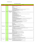
Definition of water quality and treatment requirements for drip irrigation
Parameter
Suspended solids
(mg/l)
Sand (mg/l)
Low
Concentration
Medium
High
Treatment
<20
20-60
>60
Filtration*
<1
1-5
>5
Hydrocyclone sand separation
& filtration*
Filtration*
Silt & Clay (mg/l)
<20
20-60
>60
Calcium conc.
<50
50-300
>300
pH rectification
(as CaCo 3) (mg/l)
Iron (mg/l)
<0.1
0.1-0.5
>0.5
Oxidization & iron removal
Manganese (mg/l)
<0.02
0.02-0.3
>0.3
Oxidization & manganese removal
Sulfide (mg/l)
<0.01
0.01-0.2
>0.2
Oxidization & purification
Algae
Treatment at water source;
<0.3
0.3-0.8
>0.8
(Chlorophyll A) (mg/l)
Filtration & chlorination
Plankton Plankton
<2
2-20
>20
Treatment at water source & filtration
(details) Copepod
<5
5-50
>50
Treatment at water source & filtration
Rotifer
<50
50-200
>200
Filtration (low concentration)
Dissolved
Treatment at water source;
oxygen
<0.5
0.1-0.5
0.1>
pumping point
(mg/l)**
(add if higher concentration)
pH
pH rectification to required level acording to crop and soil
Treatment at water source
Phosphorous (mg/l)
<1
1-10
>10
(nutrients or sewage)
Hetrotropic bacteria
Treatment at water source;
0
Presence Colonization
(bacterial slime)
purification
Sulfuric bacteria
0
Presence Colonization Sulfide removal & purification
Iron &
Iron & manganese removal
0
Presence Colonization
Manganese bacteria
& purification
Col. Protozoa
0
Presence Colonization Regular purification
Bryozoa
0
Presence Colonization Purification & filtration
Snails and shells
0
Presence Colonization Avoid development
Sewage treatment, filtration
BOD sewage (mg/l)
<10
10-50
>50
& chlorination
*In extreme cases sedimentation prior to filtration is required.
**Although it does not lead directly to clogging of the drippers, a lack of oxygen in the water usually
indicates the presence of sulfide. A lack of oxygen in sewage indicates a poor level of sewage treatment.
Water analysis
A water analysis is necessary in order to select the appropriate type of filtration system, to prescribe
a suitable maintenance program, to select the type of dripperlines and to prescribe an appropriate
Nutrigation™ plan (see Water analysis, page 76).
16 DRIP IRRIGATION HANDBOOK
DRIP IRRIGATION SYSTEM OVERVIEW
Types of filters
The types of filters used most often in drip irrigation systems are:
Media filters (gravel or sand) are necessary for any surface water
source and especially so for wastewater. They consist of a metal or
plastic enclosure incorporating small gravel stones or sand, which
traps the dirt. This filter includes a flushing system for washing the
gravel or sand and returning the dirt to the water source.
ATTENTION
It is highly recommended to install a screen filter downstream
the media filter in order to prevent infiltration of filter medium
into the system in the event of a malfunction of the media filter.
Disk filters are used with surface water systems, wells or
municipal water sources. These filters are comprised of a series
of grooved plastic disks stacked together with a total equivalent
screen size ranging from 40 to 400 mesh.
These filters enable deep three-dimensional filtering (e.g. allow
entrapping of more particles as water passes through the pores
created by the grooves in the surfaces of the filtering disks stacked
together in the filter).
Having more surface area than screen filters, disk filters are better
suited for higher flow rates.
Screen filters are used mainly as secondary filters with surface
water systems or as primary filters with well or municipal water
sources. A screen filter is comprised of a cylinder with a net that
traps the dirt. This filter is intended for relatively clean water; its
use is less common with water from a reservoir or pumped water.
ATTENTION
In any type of filter, the dirt returned to the water source
should be discharged as far as possible from the suction
point. In a streaming source (e.g. a river) the discharge
point should be downstream from the suction point.
Hydrocyclone sand separators are used as a preliminary stage of
filtration in the presence of sand or other heavy particles (50 micron or
bigger) in the source water. It utilizes centrifugal force to separate the
particles from the water. The separated material drops down into a
tank or reservoir where it can be removed later.
It is not a true filter, since there is no physical barrier to separate out
the particles, but it is often used before a filter to first remove the
bulk of the contaminant, where the filter does the final cleaning. This
type of design reduces the time required to flush and clean the main
filter. Each hydrocyclone model has its specific operation flow rate
range, it will not perform outside this range.
DRIP IRRIGATION HANDBOOK 17
DRIP IRRIGATION SYSTEM OVERVIEW
Filter screen/disk size
The relevant term for drip irrigation is the size of the gaps between fibers in the filter, in Micron (1/1000mm).
Mesh size represents the number of pores (openings) per linear inch (typically 40-200) but does not
represent the size of each pore.
Since the filtration industry traditionally uses mesh size, see the table below for Micron/Mesh conversion:
Micron (size of gaps between fibers)
420 250 177 125 105 100 75
Mesh (number of pores per linear inch) 40 60 80 120 140 155 200
Considerations for comparison between automatic filters
Consideration
Removal
efficiency
of different
suspended
particles
and general
operation
Component
Suspended solids (general)
General filter level
Sand (following hydrocyclone)
Silt and clay
Algae (< 40 micron)
Zooplankton
Iron and manganese (after oxidization)
Slime
Technical
Low supply capacity
and hydraulic
Very high supply capacity
considerations
Minimum flushing pressure (bar)
Quantity and cost of flushing water
Water in flushing cycle
Capacity required for flushing
Complexity of system
Corrosion proof
Operational
Operational and maintenance requirements
and
Frequency of operational failures
maintenance
considerations Expertise required
Cost of maintenance
Financial
Cost of system
considerations Cost of accessories
(pressure, capacity and non-return valves)
Cost of m3 /hr of filtered water
System depreciation
18 DRIP IRRIGATION HANDBOOK
Screen
Gravel/Sand
Disc
2.2
2.0
1.5
Check and compare
Check and compare
Add to cost of system
Total cost of supply in m3 /hr
Add to calculation
DRIP IRRIGATION SYSTEM OVERVIEW
Filtration requirements
The design of a filtration system involves selection of filter type and filter size (capacity) depending on the
water source and the amounts of particulate matter, carbonates and iron in the water supply and the kinds
(if any) of nutrients and/or chemical stock solutions to be injected.
The type of filtration to be used is carefully selected at the planning stage according to the general
quality of the irrigation water, and the presence of various substances in it, with respect to the specific
requirements of the irrigation system.
NOTE
If a hydrocyclone sand separator is required, make sure it suits the flow rate range of the planned system.
Water quality and drippers specifications will determine the filtration type, level (effective mesh size) and
quantity. Most drip irrigation systems require filtration of 130 micron (120 mesh) or higher (filters may also
be specified by the maximum particle size that will pass it - in microns).
NOTE
In general, the biggest filter opening should be one tenth the size of the smallest dripper passageway.
ATTENTION
Standard irrigation filters will NOT remove salt or dissolved solids.
ATTENTION
Always install a filter when setting up a drip irrigation system. Even if potable water is used, a
basic screen filter is still required.
A well planned drip irrigation system includes 2 stages of filtration:
Main (Primary) filtration
• Responsible for filtering relatively large particles near the water source.
• Comprised of a media or disk filter.
• A hydrocyclone sand separator shoud be place before the main filter in cases where sand or other
heavy particles (50 micron or bigger) are present in the source water.
Secondary filtration
• Responsible for filtering relatively small particles remaining after the main filtration stage.
• Two types of filters can be used for secondary filtration: • Screen filter
• Disc filter
DRIP IRRIGATION HANDBOOK 19
DRIP IRRIGATION SYSTEM OVERVIEW
Main, sub-main, distribution pipes and fittings
Main, sub-main, distribution pipes
Pipelines carry water through the entire irrigation system, from the pump through the filters, the valves,
and onward to the drippers.
ATTENTION
All pipelines and fittings should be properly sized to withstand maximum operating pressures and
convey water without excessive pressure loss or gain.
PVC piping may be used throughout the system or combined with steel piping at the pump station. PVC,
polyethylene (PE) or flexible pipes (PolyNet™/FlatNet™) are used for sub-mains and distribution pipes.
ATTENTION
Be sure to consider the expansion and contraction that occurs under normal on-surface operating
conditions (each type of pipe is affected to a different degree).
ATTENTION
Pipelines are connected to one another with welds, glue or friction fittings, according to the type
of piping in use, and are anchored to the infrastructure supporting them. Make sure all pipelines
are properly secured and anchored.
NOTE
In a subsurface drip irrigation (SDI) system, the pipeline is more difficult to access and repair.
Making sure all fittings are secure at installation can save significant repair issues later.
Particular attention is required especially after the initial growth stage of the crop.
In irrigation design, pipe sizes are specified based on economic, friction loss, water hammer
considerations and flushing concerns. As pipe size increases, friction loss decreases (reduced pumping
cost) but initial cost increases.
NOTE
In most cases the distribution pipe is installed below the elevation of the dripperlines so that solids
will tend to collect in it rather than in the dripperlines.
Irregular field shapes are common due to topography and property boundaries. At the planning stage, care
is taken to properly size sub-main and distribution lines where field shape varies. Sub-main and distribution
lines for irregularly shaped fields are designed based on actual flow rates of the dripperlines and not on an
“average” flow rate of the system.
NOTE
The piping system must be designed not only to allow the flow rate necessary for normal irrigation
but also to allow sufficient flow rate for proper flushing velocities in the system (recommended
minimum: 0.3 meter/sec; 1 foot/sec). For flushing instructions see Flushing the main, sub-main
and distribution lines, page 71).
Design objectives for flushing may result in different pipe diameters being selected than those selected
in the design process for normal operation. This is because the flushing flow rate required for achieving a
desired flushing velocity in any section of a main, sub-main or distribution pipe may be different than the
design flow rate for regular operation.
20 DRIP IRRIGATION HANDBOOK
DRIP IRRIGATION SYSTEM OVERVIEW
Structure of the cross section of a pipe
• The Outside Diameter (OD) of the pipe is the distance between the outside
walls of the pipe, measured perpendicularly to the pipe’s axis.
• The Inside Diameter (ID) of the pipe is the distance between the internal
walls of the pipe, measured perpendicularly to the pipe’s axis.
• Wall Thickness (WT)
Pipe’s Inside Diameter = ID = OD - (2 * WT)
WT
OD
Pipe’s Wall Thickness = WT =
ID
OD – ID
2
NOTE
The relevant pipe diameter or calculations regarding flow rate and velocity in a pipe is the Inside
Diameter (ID).
EXAMPLE
A selection of polyethylene (PE) pipes demonstrating the relation of the
pipe's Inside Diameter (ID) to the Outside Diameter (OD):
Pipe
Outside Diameter
diameter/class*
(OD) (mm)
63/12
63
75/12
75
90/12
90
110/12
110
125/12
125
140/12
140
160/12
160
200/12
200
225/12
225
250/12
250
Wall Thickness
(WT) (mm)
4.70
5.60
6.70
8.10
9.20
10.30
11.80
14.70
16.60
18.40
Inside Diameter
(ID) (mm)
53.60
63.80
96.60
93.80
106.60
119.40
136.40
170.60
191.80
213.20
*By international standard ISO 4427/07.
For more info, see Polyethylene Rigid and Flexible Pipes - Product Catalog at
http://www.netafim.com/irrigation-products-technical-materials.
Fittings
A wide variety of fittings are available to fit any drip irrigation system and any type of pipes used.
The selection of fittings is a planning issue defined by the project's BOM (Bill of Material).
For more info see Fittings & Accessories Product Catalog at
http://www.netafim.com/irrigation-products-technical-materials.
DRIP IRRIGATION HANDBOOK 21
DRIP IRRIGATION SYSTEM OVERVIEW
Water meters and pressure gauges
Make sure your system has a water meter and pressure gauges in working order! Although simple,
these gauges are often overlooked or not maintained. These monitoring devices are essential to proper
system operation. System flow rate helps detect leaks or clogging, and must be known to determine the
application rate for irrigation scheduling purposes. System pressure also helps detect leaks or clogging,
and is essential for managing filters, chemical injectors and the whole system within its operating range.
Water meters
Water meters provide information regarding water application that is
essential for irrigation scheduling, and for the monitoring of dripper clogging.
Propeller meters are the most common type in agricultural applications.
NOTE
All types of water meters require regular maintenance. Follow the
manufacturer’s recommendations for required maintenance.
A water meter installed at the head of a drip irrigation system or small water
meters placed at the head of selected dripperlines can help in detection of
dripper clogging.
A single, large water meter at the head of the drip irrigation system
monitors the flow rate to the entire system. Most water meters
incorporate a totalizing register that records the total flow (m3, gallons)
passing through the meter. Some meters also have an instantaneous
flow rate indicator (measured in m3 /hr, GPM).
Make sure that the pipe in which the water meter is installed is flowing
full (the water flowing fills the entire cross section of the pipe without
air pockets) and that there is not excessive turbulence in the pipe. A
water meter installed close to a valve, elbow, or tee (T) may not provide
accurate information. If the meter has an instantaneous
(e.g. m3 /hr, GPM) indicator, an excessive fluctuation of the indicator
needle is a sign of excessive turbulence in the meter.
To detect clogging or leaks in the irrigation system, check the flow rate in the system weekly (see
Preparation and Use of a Hydraulic Conditions Checklist, page 74). A decrease in flow rate over time may
indicate clogging. Before checking the flow rate, check that the pressure in the system is as planned. For
accurate and useful data about the drip irrigation system to be acquired, the operating pressure of the
system must be as initially planned each time the flow rate is checked. If the operating pressure is allowed
to vary, the acquired flow rates will be valid but will not be usefully compared for the purpose of clogging
detection.
Using a number of small water meters (throat size 5/8” or 3/4”) to monitor flow rate to individual
dripperlines (laterals) provides greater sensitivity to clogging than does a single, large water meter at the
head of the system. Especially recommended in large projects - over 100 Ha (250 acres).
Most small water meters have only a totalizing register, so you will need to keep track of the system
operating time between water meter readings (if installed, a controller does it automatically (see Controller,
page 41). As with the large water meter, for acquired data to be valid the operating pressure needs to stay
constant over time.
22 DRIP IRRIGATION HANDBOOK
DRIP IRRIGATION SYSTEM OVERVIEW
Pressure gauges
Pressure gauges are essential components in a drip irrigation system. Providing
vital information concerning the irrigation system, they help in the detection of
leaks and clogging and in the management of filters, chemical injectors and in
keeping the system in its operating range.
To acquire as accurate as possible data always use a pressure gauge with a
scale representing the pressure range of the system. The typical pressure in
the system should be roughly at the midpoint of the gauge's scale.
Pressure loss across a filter
To avoid inaccuracies in the reading of the pressure loss across a filter, use a single
pressure gauge connected to a three-way selector valve, as shown.
ATTENTION
Reading the pressure loss across a filter with two different pressure gauges
installed at the inlet and at the outlet of the filter might result in inaccurate
reading due to calibration difference between the two gauges.
It is important to measure the pressure at a variety of key points along the irrigation system: at the head of
the system, at the head of each irrigation zone and at the inlet and end of selected dripperlines in the field.
TIP
Netafim™ offers a variety of nozzle adapters to be connected
at the key points in the system, enabling the use of a single
hand-held pressure gauge equipped with an insertion needle.
Pressure gauge nozzle adapters
With barb connector
With thread
for use with PE pipes
connector for
(i.e. dripperlines).
use with PVC
pipes.
DRIP IRRIGATION HANDBOOK 23
DRIP IRRIGATION SYSTEM OVERVIEW
Valves
In an irrigation system, water flow rate and pressure throughout the system should be precisely controlled
to ensure efficient and timely water application; therefore proper selection and placement of valves is critical.
Valves play key roles in controlling pressure, flow and distribution under different conditions to optimize
performance, facilitate management, and reduce maintenance requirements.
ATTENTION
Valve sizes, maximum working pressure and valve materials should be selected properly to meet
the system demands. Oversized valves may not open or close properly while undersized valves
may restrict flow and cause excessive pressure loss.
Valves used in a drip irrigation system include:
Manual control valve
4 common types of manual control valves are used in drip irrigation systems:
Ball valve
The ball valve is a quarter-turn valve. In a ball valve the closing mechanism is a sphere (ball)
with a port through the middle, connected to a lever in line with it that shows the valve's
position. Rotating the lever turns the ball so that when the port is in line with the pipe, flow
will occur, and when perpendicular to the pipe, flow is blocked. Designed to be fully opened
or closed and is not suitable for regulating the flow.
Butterfly valve
The butterfly valve is a quarter-turn valve. Operation is similar to that of a ball valve. The closing
mechanism takes the form of a disk positioned in the center of the pipe. A rod connected
to the lever passes through the middle of the disc is. Rotating the lever turns the disc either
parallel or perpendicular to the flow. Unlike a ball valve, the disc is always present within the
flow; therefore a slight pressure drop is always induced in the flow, regardless of valve position.
Designed to be fully opened or closed and is not suitable for regulating the flow.
Gate valve
The gate (sluice) valve opens by lifting a gate (wedge) out of the path of the fluid. When the
gate valve is fully open, there is no obstruction in the flow path, resulting in very low friction
loss. Designed to be fully opened or closed and is not suitable for regulating the flow.
Globe valve
A globe valve is the only type of manual valve recommended for regulating the flow with
minimum friction loss. It consists of a movable disk plug aligned with a fixed ring located in
the stream. Operated by screw action using a handwheel.
Check valve (One-way valve)
The function of the check valve is to prevent water flow in the opposite direction to that desired.
It serves various purposes:
• Installed at the outlet of a pump that pumps water to a field at a higher elevation protects the pump from the back wave of water hammer.
• Installed at the outlet of a filter, which conveys water to a higher field prevents water from flowing back through the system's head components.
• Installed upstream from a dosing unit prevents fertilizers and chemicals infiltration of the water source.
• Installed on the inlet pipe of a pump, as a foot valve, enables priming of the inlet pipe.
24 DRIP IRRIGATION HANDBOOK
DRIP IRRIGATION SYSTEM OVERVIEW
Hydraulically operated, diaphragm-actuated control valves
Serve different purposes according to the
layout of the valve's control loop.
Open
Closed
Hydraulic control valve
Opens and shuts off in response to a local or remote pressure command.
Pressure Reducing Valve (PRV)
Reduces higher upstream pressure to lower constant downstream pressure regardless of fluctuating
demand, and opens fully upon line pressure drop.
For optimal operation the pressure ratio across a PRV should not be higher than 1:4.
Pressure relief/sustaining valve
Can fulfill either of two separate functions:
• When installed in-line, it sustains minimum preset upstream pressure regardless of fluctuating flow or
varying downstream pressure.
• When installed as a circulation valve, it relieves line pressure in excess of preset.
Pressure reducing and sustaining valve
Fulfills two independent functions at the same time:
It sustains minimum preset upstream pressure regardless of fluctuating flow or varying downstream
pressure and it prevents downstream pressure from rising above maximum preset, regardless of
fluctuating flow or excessive upstream pressure.
Pressure relief valve
Relieves excessive line pressure when it rises above the preset maximum. It responds to a rise in system
pressure immediately, accurately and with high repeatability, by opening fully.
Booster pump control valve
A double chambered, active check valve that opens fully or shuts off in response to electric signals.
It isolates the pump from the system during pump starting and stopping, to prevent pipeline surges.
Surge anticipating valve
An off-line valve, sensing line pressure. It opens in response to the pressure drop associated with abrupt
pump stoppage. The pre-opened valve dissipates the returning high pressure wave, eliminating the surge.
The valve also relieves excessive system pressure.
Air valves
Combination air release valve
Evacuates large volume of air during
pipeline filling and network draining and
allows efficient release of air pockets
from pressurized pipelines.
Kinetic air valve
Evacuates large volume of air during
pipeline filling and network draining.
DRIP IRRIGATION HANDBOOK 25
DRIP IRRIGATION SYSTEM OVERVIEW
Dosing unit
A dosing unit serves Nutrigation™ and chemigation:
Nutrigation™
The most effective way to increase the yield and quality of a crop is by feeding the plant according to its
specific, ever-changing needs. This means delivering the right amount of water and nutrient at the right
time. Nutrigation™ refers to injection of nutrients for the plant.
Nutrigation™ is comprised of three stages:
• Dissolving soluble fertilizers (if required).
• Injecting nutrients according to the desired dosing ratios.
• Delivering the precise quantity of nutrients to the plant's root zone.
Chemigation
Chemigation refers to injection of chemicals to prevent or reduce dripper clogging (addition of chlorine,
hydrogen-peroxide, acid or others), and the injection of chemicals for crop and soil concerns (herbicides,
pesticides and others).
Because the water passages in drippers are relatively small, they can be clogged; therefore, along with
filtration, the capability to inject chemicals for dripper clogging control is an important feature.
Benefits of Nutrigation™ and/or chemigation:
• Uniform and timely application of nutrients and chemicals
• Reduced soil compaction due to reduced traffic in fields
• Reduced labor requirements, reduced exposure to chemicals
• Reduced environmental contamination.
The design of a chemical injection system involves the selection of injector type and capacity. If the
injection system is to be used for Nutrigation™, the injection unit is sized for this use since injection rates
for nutrients are usually much higher than injection rates for chemicals such as liquid chlorine or acid.
Any components coming in contact with nutrients, chlorine, or acid should be resistant to corrosion. Some
countries require specific types of injectors for agrochemicals. Always follow local laws and chemical labeling
requirements.
Nutrients and chemicals may be injected into pressurized drip systems via a variety of methods:
Netafim™ offers a comprehensive array of dosing systems to ensure precise nutrient delivery for any crop,
plot size and application.
Relevant terms:
• Single dosing channel - for injection of only one type of fertilizer solution at the same time.
• Multiple dosing channels - for injection of several fertilizer solutions at the same time or of a single
fertilizer solution at a higher rate.
• Bulk/Quantitative Nutrigation™ - The entire amount of fertilizers is injected in one shot.
• Proportional Nutrigation™ - The fertilizers are injected at a constant ratio relative to the flow of irrigation
water in the main line.
• Nutrigation™ based on EC and pH control - Nutrigation™ is constantly adjusted in order to keep a steady
EC and pH level according to the plant's needs.
Can be conveniently accomplished with a controller (Netaflex™, NetaJet™ or FertiKit™) on the dosing
system and EC and pH sensors on the dosing unit.
26 DRIP IRRIGATION HANDBOOK
DRIP IRRIGATION SYSTEM OVERVIEW
Fertilizer tank
A fertilizer tank mixes water with fertilizer for quantitative Nutrigation™.
It is operated by the hydraulic pressure in the irrigation system and does
not need an external energy source (subject to excess pressure available
in the system). The desired amount of fertilizer placed in the tank is
dissolved and injected into the irrigation system.
Can be connected to the irrigation system in two ways:
• Inline - installed directly on the main line
(typical of very low capacity systems).
• Bypass - installed as a bypass from the main line, a manual or hydraulic
pressure reducing valve (PRV), installed on the main line, produces the
required pressure differential to operate the fertilizer tank (typical of high
capacity systems).
Fertilizer tanks are simple to use and maintain.
Hydraulic piston motor injector
Its linear hydraulic piston motor is powered by the hydraulic pressure in
the irrigation system, and does not require any other energy source for
injecting fertilizer into the pressurized irrigation line.
Water enters the injector through the upstream inlet and exits it to the drain
line through the water outlet. The fertilizer is injected at twice the pressure
of the irrigation line, generated by the hydraulic piston motor itself.
The liquid fertilizer enters the injector through the suction port positioned
inside the fertilizer tank and is injected through the injection outlet,
downstream, into the irrigation line.
The water consumption of the hydraulic motor is 3 times the quantity
of the chemical injected and it can produce an injection flow rate of
up to 320 liter/hour (1.4 GPM), depending on the inlet pressure and
the pump model.
Can be operated manually or automatically by an irrigation controller.
Netafim™ Venturi Injector - up to 2"
A Venturi injector uses excess pressure in the irrigation system to create a low pressure zone, or vacuum,
in the injector throat. This vacuum efficiently draws chemicals into the pressurized water line, eliminating
the need for a separate chemical injection pump.
Venturi injectors are the most cost-effective method of introducing
chemicals into a pressurized irrigation system, popular because
2.0"
of their simplicity, reliability and low cost, and because they don’t
require a power source.
0.75"
Can be easily connected to the irrigation system in two ways:
• Inline - installed directly on the main line
(typical of very low capacity systems).
• Bypass - installed as a bypass from the main line, a manual or
hydraulic pressure reducing valve (PRV), installed on the main
line, produces the required pressure differential to operate the
Venturi injector (typical of high capacity systems).
Venturi injectors include no moving parts and require little
maintenance.
They supply an extremely uniform injection rate from start to finish at
nominal system flows rates.
Chemical injection capacity: 30 - 1200 l/hr (8 - 320 GPH) depending
on injector size and operating pressure.
Can be operated manually or automatically by an irrigation controller.
DRIP IRRIGATION HANDBOOK 27
DRIP IRRIGATION SYSTEM OVERVIEW
Electric dosing pump
Intended for flow rates up to 25 l/hr (6.6 GPH), the electric pump
is usually used for injection of chemicals and acids for system
maintenance.
Maximum pressure: 10 bar (145 PSI).
Hydraulic fertilizer injector (proportional)
Applies fertilizers and chemicals proportionally to the water flow through an irrigation
system in the slow and constant quantities required for steady growth.
Widely used in open fields, orchards and landscaping to inject an additive into a water
line at a consistent injection rate under varying water pressure and flow rates.
This process, injecting additives using only water power, is accurate and simple.
• Water driven, non-electric
• Piston driven by water flow
• Solution is added in proportion to water flow for accurate mixing
• Solution is constantly added as water flows through the unit
• Ratio of additive remains constant
Single channel Mini FertiKit
Venturi injector with booster. This method is used when the
pressure differential in the main line is not sufficient to activate
a basic Venturi dosing unit. The booster pump creates additional
pressure to activate the Venturi while preventing head loss to the
system. Supplied with selected size of Venturi (up to 3/4").
A check valve should be installed upstream from the bypass.
Can be operated manually or automatically by an irrigation
controller.
28 DRIP IRRIGATION HANDBOOK
DRIP IRRIGATION SYSTEM OVERVIEW
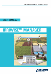
FertiKit3G™
The FertiKit3G™ is a highly versatile and precise dosing system
suitable for an unrivaled range of irrigation system capacities. Covers
all applications ranging from open fields to intensive horticulture.
Requiring a minimal investment, the FertiKit3G™,
a CE-compliant modular system, is the industry's most cost-effective
dosing system, whether used for small or large-scale applications.
• Flexible: Works with a very wide range of dosing
channel flow rates up to 6 units of 50 to 1000 l/hr.
• Scalable: For systems from 5 m3 /h to 700 m3 /h capacity
and pressures up to 8.0 bar.
• Cost-effective: Requires minimal investment
with rapid ROI.
• Modular: Available in four models including two that
do not require a booster pump.
NetaFlex3G™
The NetaFlex3G™ is a reliable, state-of-the-art, open-tank dosing
system ensuring very precise and even nutrient dosing for
greenhouse crops.
A CE-compliant modular system, the NetaFlex™ easily integrates with
multiple Netafim™ and third-party control and monitoring systems, while
delivering a uniform quantity or ratio of nutrients.
• Productive: Employs precise EC and pH control to assist in
delivering a high-quality product with outstanding yields.
• Uniform: Delivers a consistent quantity or ratio of
nutrients in a homogenous solution thanks to an open
mixing tank design.
• Flexible: Works with a wide range of dosing channel flow
rates up to 6 units of 50-600 l/hr.
• Scalable: System flow rates from 5 m3 /h to 60 m3 /h capacity.
• Focused: Made for greenhouse applications.
NetaJet3G™
The NetaJet3G™ is a uniform low-energy dosing system featuring a
state-of-the-art mixing chamber.
It provides the highest level of dosing precision and uniformity for
greenhouse and open-field crops.
A CE-compliant modular dosing system, the NetaJet3G™ easily integrates
with multiple Netafim™ and third-party control and monitoring systems.
• Productive: Employs precise EC and pH control to deliver consistently
high-quality product with outstanding yields.
• Uniform: Delivers a consistent quantity/ratio of nutrients thanks to an
innovative mixing chamber while maintaining perfect EC and pH control.
• Flexible: Works with a wide range of dosing channel flow
rates up to 5 units of 1000l/hr dosing channels.
• Cost-efficient: Using a single pump for mixing and
injection of nutrients, the NetaJet3G is designed to
accurately dose with low levels of energy consumption.
• Scalable: Scales from 5 m3 /h to 400 m3 /h capacity and
pressures up to 6.5 bar.
• Versatile: Suitable for applications ranging from greenhouses
to net houses.
DRIP IRRIGATION HANDBOOK 29
DRIP IRRIGATION SYSTEM OVERVIEW
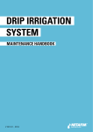
Select the appropriate dosing unit:
Single
Multiple
ou
ss
oi
lle
-s
Co
m
m
en
ts
se
ou
nh
ee
Gr
Gr
ee
nh
ou
se
-s
rc
/o
fie
ld
Op
en
d
ire
qu
Re
oi
l/
rd
ha
re
gy
er
en
it
un
ne
ur
so
an
ch
in
g
os
fd
ro
Do
be
um
N
si
ng
Will work only if the pressure difference between
inlet and outlet is at least 0.3 bar (3 meters).
Consumes water 3 times the quantity of the
chemical injected.
Requires 15-75% pressure differential for optimal
operation, according to the required injection rate.
Fertilizer tank
Hydraulic piston
motor injector
Netafim ™ Venturi
injector
Electric dosing
pump
Hydraulic fertilizer
injector (proportional)
Single channel
Mini FertiKit
FertiKit3G™
th
ce
ne
ls
se
Recommended for:
Requires 15-30% pressure differential for optimal
operation, according to the required injection rate.
Legend:
or
NetaFlex3G™
NetaJet3G™
For detailed technical data, see the product's datasheet at
http://www.netafim.com/irrigation-products-technical-materials.
For clarifications or in case of doubt consult a Netafim™ expert.
30 DRIP IRRIGATION HANDBOOK
Electricity is available on site.
Extra pressure is available in
the system in addition to the
required pressure for current
irrigation.
DRIP IRRIGATION SYSTEM OVERVIEW
Dripperlines (laterals)
Dripperlines are at the heart of a drip irrigation system. In any irrigation system, the design process starts
at the plant and proceeds to dripperline design. It is important to know what to take into consideration
during dripperline design: dripperline selection, wall thickness, dripper flow rate, spacing between drippers,
spacing between dripperlines, and specification of dripperline insertion depth (in SDI).
Basic terms regarding dripperlines:
Structure of the cross section of a pipe
• The Outside Diameter (OD) of the pipe is the distance between the outside
walls of the pipe, measured perpendicularly to the pipe’s axis.
• The Inside Diameter (ID) of the pipe is the distance between the internal
walls of the pipe, measured perpendicularly to the pipe’s axis.
• Wall Thickness (WT)
Pipe’s Inside Diameter = ID = OD - (2 * WT)
The area of the inside pipe’s cross-section = A =
• π = 3.1416
• r = ID/2
WT
OD
Pipe’s Wall Thickness = WT =
ID
OD – ID
2
π ID 2
= π r2
4
Uniformity and efficiency
Uniformity saves water and fertilizer and improves yield, resulting in shorter ROI.
Efficiency saves resources and preserves the environment while optimally serving the crop's needs.
ATTENTION
Low startup costs can result in high annual operating costs. When designing a drip irrigation
system it is important to consider uniformity and efficiency in order to keep total cost low.
NOTE
By international standards, 10% flow variation is considered uniform irrigation.
For more details and calculations of uniformity and efficiency, see pages 49.
Drippers
The drippers incorporated at uniform spacing along the dripperline deliver water and nutrients directly to
the plant root zone.
A typical drip irrigation system includes thousands of drippers. Each dripper should be durable, resistant
to clogging, and emit the same amount of water. Wide water passages guarantee long-term trouble-free
performance.
The flow rate and spacing of the drippers is important in determining the wetting pattern and for the
prevention of runoff or deep percolation.
A properly operated and maintained drip irrigation system provides water and nutrients to the crop root
zone without runoff or deep percolation.
DRIP IRRIGATION HANDBOOK 31
DRIP IRRIGATION SYSTEM OVERVIEW
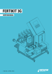
Two types of integral drippers are available:
Non pressure compensated drippers
Non-PC drippers supply a flow rate that is based on
Non-PC Dripper
the working pressure.
• The dripper flow rate, pipe diameter and dripper
spacing determine the pressure head losses in
water flow within the dripperline.
• Differences in topographic heights also affect the system.
These two factors produce small differences in the dripper flow rates within the same dripperline.
Pressure Compensated (PC) drippers
As long as the working pressure remains within the
allowable pressure range, PC drippers provide uniform
irrigation by maintaining a constant flow rate regardless
of the working pressure.
PC Dripper
The diaphragm is activated by the continual differential
pressure created by the dripper's labyrinth, thus
maintaining a constant dripper flow in a wide pressure range.
Thanks to the free-floating diaphragm, the dripper’s action is precise, immediate, sensitive, continually
self-adjusting and constantly self-flushing. Particles that cause clogging will either be flushed out through
the wide water passages or increase the pressure differential. This causes the diaphragm to momentarily
increase the cross-section volume for outgoing water, and thus flush the dirt out of the system.
The diaphragm movement maintains constant differential pressure within the water passage, resulting in a
uniform flow rate at a wide pressure range.
Additionally, Netafim™ PC drippers have the added benefit of the exclusive constant self-flushing feature,
which aids in the prevention of clogging.
NOTE
PC drippers deliver the same flow rate regardless of the dripperline length (as long as the drippers
operate within its working range as determined by the manufacturer).
PC drippers for particular applications:
Anti-Siphon (AS) drippers
The anti-siphon (AS) mechanism prevents suction of dirt into the dripperline, providing critical protection
against dripper clogging. Ideal for subsurface drip irrigation (SDI).
Irrigation systems do not usually operate during rain. Rain often causes saturation of the soil or standing
water around the dripperlines. Between irrigation cycles, when the system is not pressurized, it acts as a
drainage system and pollution, if ingested, can lead to drippers' clogging.
To overcome this problem, the anti-siphon mechanism seals the dripper when the system is not
pressurized, thus preventing pollutants from entering the system.
Compensated Non-Leakage (CNL) drippers
The CNL feature prevents system drainage between irrigation cycle, when the system is not fully
pressurized. It ensures uniform water and nutrient distribution during pulse irrigation.
Dripperlines remain full between irrigation cycles, eliminating drainage and refill of the dripperlines, thus
saving water.
32 DRIP IRRIGATION HANDBOOK
DRIP IRRIGATION SYSTEM OVERVIEW
Determining the type of dripper to use
The type of drippers to be used should be selected according to the project's needs and characteristics.
Although it is up to the grower to decide which type of drippers to use for a specific crop, the following
recommendations should be considered:
It is strongly recommended to use PC drippers when:
• The terrain slope is greater than 2%.
• There are topographic variations along the dripperline.
• For long dripperlines.
• The crop is highly sensitive to excessive or insufficient irrigation.
• In orchards, where poor irrigation uniformity would cause inequality in growth of individual perennial
plants (the longer the plant's life, the greater the disparity between individual plants).
• Perfect water distribution and uniformity are required.
NOTE
For subsurface systems always prefer anti-siphon (AS) drippers.
On-line drippers
Netafim™ offers a comprehensive line of on-line drippers with all the features and benefits of its integral
drippers. Designated mainly for greenhouse, nursery and fruit tree aplications.
Netafim’s on-line pressure-compensated (PC & PCJ) drippers ensure precise, efficient and uniform flow
distribution over the entire growing area and high resistance to common chemicals and nutrients.
Spider assembly
Netafim™ offers growers a range of micro tubes, manifolds and/or end-line products which, when connected
to on-line drippers can be used to direct water flow to a specific location or to irrigate a variety of points.
For more details about Netafim’s assembly products, refer to the Netafim™ Accessory Catalog, at
http://www.netafim.com/irrigation-products-technical-materials.
Dripperline selection and layout design
With any irrigation system, the design process starts at the plant and works "upstream". Hydraulically
speaking, this means that the first part of the design process of an irrigation system is dripperline design
consisting of dripperline selection and spacing between dripperlines in the field.
Dripperline selection involves consideration of spacing, pipe diameter and wall thickness, and dripper flow rates.
Consideration must also be given to connections between the dripperlines to the supply and flushing manifolds.
Dripper spacing depends on flow rate and soil characteristics. In general, coarser textured (sandy) soils will
require shorter dripper spacing than a finer textured (clayey) soil, since coarse soils allow less lateral water
movement.
NOTE
The dripperlines must be selected not only to allow the flow rate necessary for normal irrigation
but also to allow sufficient flow rate for proper flushing velocities in the system
(see Flushing the dripperlines, page 73).
Dripperline spacing depends on the crops to be grown, the processing method and the agro-machinery to
be used.
Oftentimes there will be a critical crop in rotation that will dictate spacing. In rotations that include a row
crop, dripperline spacing is most often a multiple of the row spacing.
DRIP IRRIGATION HANDBOOK 33
DRIP IRRIGATION SYSTEM OVERVIEW
Dripperline length is determined by field length and layout, allowable pressure (and therefore flow)
variation within a zone, and flushing considerations.
Dripperline length also needs to be specified; along with dripperline's diameter, this will affect flow rate
uniformity and impact flushing requirements and flow variations (particularly with drippers that are not
Pressure Compensated).
When determining the type of dripperline to be used and deciding on the distance between dripperlines,
also consider the plot geometry and the work practices.
In some regions, many fields are irregularly shaped, and therefore may have dripperlines of different lengths.
Netafim™ offers a wide selection of dripperlines suitable for various irrigation needs
Thin-walled dripperlines
• Suitable for 1-3 growing seasons.
• Especially fit for vegetables and field crops.
• Can be deployed at the beginning, and rolled-up at the end of each growing season.
Medium-walled dripperlines
• Suitable for 4-9 growing seasons.
• Designed for on-surface and subsurface (SDI) applications.
• For perennial plants, row crops and industrial row crops.
Thick-walled dripperlines
• Suitable for 10 or more growing seasons.
• Designed for a working life of many years in on-surface and subsurface (SDI) applications.
• For perennial plants, fruit trees, vineyards and the like.
Decoding the commercial name of Netafim™ dripperline models:
The name consists of 5 digits.*
Thin- and medium-wall dripperlines
• The first two digits represent the pipe's inside diameter (ID) rounded.
• The three last digits represent the pipe's wall thickness (WT) in mil.
(1 mil = 1/1000 inch = 25.4/1000 mm = 0.0254 mm).
Thick-wall dripperlines
• The first two digits represent the pipe's outside diameter (OD) rounded.
• The three last digits represent the pipe's wall thickness (WT) in millimeters (mm).
*The 5-digit commercial names of the dripperline models in the tables opposite are intended for
identification purposes only and do not represent the exact diameter and wall thickness of each dripperline.
For accurate data, refer to the Technical Datasheet of the specific product at
http://www.netafim.com/irrigation-products-technical-materials.
NOTE
The maximum allowed flushing pressures in the tables are valid when flushing for a maximum of
half an hour consecutively, with the end of 5 or more dripperlines kept open.
34 DRIP IRRIGATION HANDBOOK
DRIP IRRIGATION SYSTEM OVERVIEW
Thin-walled dripperlines
Wall Thickness
Dripperline
Pipe's Inside
model
Diameter (ID) (mm)** (mm)
(mil)
12060
12
0.15
6.0
12080
12
0.20
8.0
12125
12
0.31
12.5
12150
12
0.38
15.0
16060
16
0.15
6.0
16080
16
0.20
8.0
16100
16
0.25
10.0
16125
16
0.31
12.5
16150
16
0.38
15.0
22080
22
0.20
8.0
22100
22
0.25
10.0
22135
22
0.34
13.5
22150
22
0.38
15.0
25135
25
0.34
13.5
25150
25
0.38
15.0
35135
35
0.34
13.5
35150
35
0.38
15.0
Max. working pressure
(bar)
1.4
1.7
2.5
3.0
0.8
1.0
1.2
1.8
2.2
0.8
1.0
1.5
1.8
1.2
1.4
0.9
1.0
Max. flushing pressure
(bar)
1.6
2.0
2.9
3.5
0.9
1.2
1.4
2.1
2.5
0.9
1.2
1.7
2.1
1.4
1.6
1.0
1.2
Max. working pressure
(bar)
3.0
3.5
2.5
2.8
2.9
3.0
2.5
Max. flushing pressure
(bar)
3.5
4.6
3.3
3.6
3.8
3.9
2.9
Max. working pressure
(bar)
3.5
3.0
3.5
4.0
4.0
3.5
4.0
3.0
3.0
Max. flushing pressure
(bar)
4.6
3.9
4.6
5.2
5.2
4.6
5.2
3.5
3.5
Medium-walled dripperlines
Wall Thickness
Dripperline
Pipe's Inside
model
Diameter (ID) (mm)** (mm)
(mil)
12200
12
0.50
20.0
12250
12
0.63
25.0
16200
16
0.50
20.0
16250
16
0.63
25.0
16007
16
0.70
27.0
16008
16
0.80
32.0
22250
22
0.63
25.0
Thick-walled dripperlines
Wall Thickness
Dripperline
Pipe's Outside
model
Diameter (OD) (mm)** (mm)
(mil)
12010
12
1.00
39.0
16009
16
0.90
35.0
16010
16
1.00
39.0
16012
16
1.20
47.0
17012
17
1.20
47.0
20010
20
1.00
39.0
20012
20
1.20
47.0
23009
23
0.90
35.0
23010
23
1.00
39.0
**The outside diameter (OD) and the inside diameter (ID) of the dripperline models and the data in the
tables are intended for identification purpose only and do not represent the exact diameter and wall
thickness of each dripperline. For accurate data, refer to the Technical Datasheet of the specific product at
http://www.netafim.com/irrigation-products-technical-materials.
DRIP IRRIGATION HANDBOOK 35
DRIP IRRIGATION SYSTEM OVERVIEW
Connectors
Netafim's comprehensive range of dripperline connector systems is made of high resistance and
high durability polymers. They are functional and viable, moulded under the highest market standards
and available for all dripperline types. Use the catalog to select the right line for your application: barb
connectors, fast ring connectors, flare connectors and a vast family of start and reducing connectors.
Connectors technical data
Connectors for thick walled dripperlines
Dripperline
Commercial
Inside Diameter
name
(ID) (mm)
Barb
12
10.2
16
14.2
17
14.6
20
17.5
Flare for HWD (orange nut)
16-17
14.2-14.6
20
17.5
23
20.8
Wall Thickness
(WT) (mm)
Subsurface installation
Deep
Shallow
insertion
insertion
Features
Allows
laying/recoiling Reusable
Subsurface installation
Deep
Shallow
insertion
insertion
Features
Allows
laying/recoiling Reusable
1.0-1.2
0.9-1.2
1.2
1.0-1.2
0.9-1.0
0.9-1.0
0.9-1.0
Connectors for thin/medium walled dripperlines
Dripperline
Commercial
Inside Diameter
name
(ID) (mm)
Ring fast connectors
16 blue ring
16.2
16 black/
15.5
white ring
22 blue ring
22.2
25 black ring
25.0
Flare for TWD (blue nut)
12
11.8
16
16.2
22
22.2
25
25.0
35
35.0
Twist lock (TWD)
16
16.2
22
22.2
25
25.0
Suitable
Not suitable
Wall Thickness
(WT) (mil)
6.0-25.0
27.0-32.0
8.0-25.0
13.5-15.0
6.0-25.0
6.0-20.0
8.0-25.0
13.5-15.0
13.5-15.0
6.0-20.0
8.0-25.0
13.5-25.0
Suitable but not recommended
For full information, see Connectors Catalog at
http://www.netafim.com/irrigation-products-technical-materials.
36 DRIP IRRIGATION HANDBOOK
DRIP IRRIGATION SYSTEM OVERVIEW
End of dripperlines
Dripperline flushing manifold
The flushing manifold at the end of the
dripperlines is fitted with a flushing
riser and valve to allow flushing of the
dripperlines. When the flushing valve is
opened, flow rate and velocity through
the dripperlines are greater than those
in normal operational mode. The higher
flow velocity allows removal of settled
solids and precipitants from the system,
preventing them from clogging the
drippers.
Flushing valve
Flushing manifold
Flow regimes may be quite complicated in irregularly-shaped fields with different dripperline lengths
within the same irrigation zone.
Since SDI zones with flushing manifolds are closed-loop systems, pressure tends to equilibrate and zones
with differing dripperline lengths are designed using an average dripperline length. Flushing manifold pipe
sizes are determined in consideration of the flow through the end of the dripperlines during flushing.
The flushing manifold is sized for a flow velocity of at least 0.3 m/sec (1 ft/sec) through the dripperlines to
ensure sediment removal.
Flushing will temporarily increase the flow requirements of the system, which in turn will decrease
the system pressure. In some cases, in order to achieve the desired velocity, especially with pressure
regulated zones or with irregular field shapes, the planning of the system may require large amounts of
piping to connect the ends of all the dripperlines in a particular section or zone.
A careful balance between flushing velocities in the manifolds and in the dripperlines is critical.
When zones are relatively large, to enable the pumping system to supply the flow rate required to achieve
the desired flushing velocity at the ends of the dripperlines, the irrigation zone is divided into two or more
flushing manifolds. This separation will allow maintenance of a proper flushing pressure.
Another solution to supply the flow rate required for flushing is to use an additional pump at the head of
the system. The additional pump will be activated only during flushing to add the missing flow rate.
DRIP IRRIGATION HANDBOOK 37
DRIP IRRIGATION SYSTEM OVERVIEW
Other flushing solutions
It is possible to flush the dripperlines manually. There are a number of ways to do this:
Solution
Description
Advantages
Folded
• Cut a 5 cm sleeve from the end of the dripperline. • Least
dripperline • Fold the end of the dripperline in the shape of a “z”
expensive
end
and slip the sleeve over the end.
solution.
• Allows
flushing of the
dripperlines
one by one
under optimal
conditions.
End of line • Slip one loop of the connector onto the dripperline. • Allows flushing
removable • Fold the end of the dripperline and slip it into the
of the
connector
connector's other ring over the end.
dripperlines
one by one
under optimal
conditions.
Disadvantages
• Requires
extensive labor
time.
• Reinstalling the
sleeve while
the dripperline
is still
pressurized is
difficult.
• Requires
extensive labor
time.
Dripperline • Pulling the orange handle
manual
to the upwards position
valve
opens the end of the
dripperline for flushing.
• None
Automatic
flushing
valve
• Flushes all the dripperlines
of the irrigation shift at the
start of each irrigation event
without human intervention.
38 DRIP IRRIGATION HANDBOOK
• Allows
flushing of the
dripperlines
one by one
under optimal
conditions.
• Requires less
labor time.
• All dripperlines
are flushed
at the start of
each irrigation
event.
• Excellent
flushing
frequency.
• All dripperlines
in each irrigation
shift are
flushed at the
same time.
• For correct
operation an
additional flow
rate of 300 l/hr
is required for
each automatic
flushing valve
operated in the
irrigation shift.
DRIP IRRIGATION SYSTEM OVERVIEW
Sensors
In order to make full use of the advantages of a drip irrigation system, it is important to regularly monitor
the actual condition of the soil, the irrigation water and the crop. To easily collect useful data for the
management of the irrigation system, Netafim™ offers a comprehensive range of high-quality sensors,
either standalone or connectable to a Netafim™ CMT controller.
Tensiometer
A tensiometer measures soil moisture. It is an instrument designed to measure the
tension or suction that a plant's roots must exert to extract water from the soil. This
tension is a direct measure of the availability of water to a plant.
Vacuum
gauge
Tensiometers may be used in any irrigated crop; however, it is with horticultural crops in
particular that they provide a suitable method to aid irrigation decisions.
The measurement of soil moisture with a tensiometer provides a valuable tool to
schedule irrigation. Tensiometers are particularly useful to determine when to irrigate, and
can be used to support a schedule based on estimation of crop water use from reference
crop evapotranspiration (EVT) data.
A tensiometer consists of an air tight, water filled tube with a porous ceramic tip at the
bottom and either a vacuum gauge at the top or a re-sealable rubber bung designed to
insert a portable vacuum meter. During the irrigation season the tensiometer is partly
inserted into the soil to a suitable depth and, when used properly, will enable improved
irrigation management by accurately determining when water should be applied to
maintain optimum crop growth and how much water should be applied to avoid over-irrigating.
Placement of tensiometers
It is recommended to use 3 tensiometers in each tensiometer
station. Correct placement is very important. Each tensiometer
should be installed with its ceramic tip at a different depth (e.g.
30, 60 and 90 cm or 12, 24 and 36 inches) according to the type
of crop (consult an agronomist).
Upper
Middle
Water
filled
tube
Porous
ceramic
tip
Lower
The upper tensiometer placed at the top of the root zone,
provides data regarding the development of the wetted bulb in
the soil and indicates when it is time to irrigate.
The middle tensiometer placed at approximately the midpoint of
the main fibrous root system (where irrigation water is certain
to wet the soil), provides data regarding the wetness of the soil
in the root zone. Placement too deep in a shallow rooted crop
will result in the crop being irrigated too late and suffering water
stress. Shallow placement in a deep rooted crop may result in
excessive irrigation and water logging of the deeper roots.
The lower tensiometer placed at the bottom of the root zone
serves as a safeguard against excessive irrigation by providing
data regarding runoff or deep percolation. Used to determine if
too much (never reads above 15 kPa) or too little water (continues
to rise) is being applied in each irrigation.
DRIP IRRIGATION HANDBOOK 39
DRIP IRRIGATION SYSTEM OVERVIEW
Locating tensiometer stations
In most situations two sites will be needed for each major species or
variety and soil type. Avoid high or low locations, zones of poor water
infiltration, and areas that are lightly watered because of bad irrigation
distribution patterns. All tensiometers must be marked clearly to avoid
damage from traffic, workers and cultivation.
For tensiometer operation and reading, see page 93.
Pressure sensor
The pressure sensor, installed on a specific lateral, main or submain line, provides actual and accurate reading of water pressure.
Netafim's electrical pressure sensor is available in 2 models:
0-6 bar and 0-2 bar.
When connected to the uManage™ real-time crop management
decision support system, pressure can be presented graphically
or in a detailed report.
This data is critical for cross-referencing between irrigation events, filter blocking, etc.
The pressure sensor can be used to measure the level of water in a storage tank and the level of liquid
solution in a fertilizer tank.
Ech2o sensor
The Ech2o soil moisture probe is a capacitance-type sensor
that measures the dielectric constant or permittivity of the
material in which it is inserted, by finding the rate of change of
voltage on the sensor that is embedded in the medium.
Water has a permittivity of about 80, while the value for soil
minerals is around 4, and for air is 1. The high permittivity of
water relative to soil minerals and air results in relatively large
changes in the permittivity of soil when the water content
changes.
The Ech2o sensor is designed to remain in the soil permanently
or for an entire growing season and requires no maintenance.
NetaSense sensor
The NetaSense sensor is a volumetric soil moisture sensor based on
TDT (Time Domain Transmission) technology that provides an immediate and
accurate response to changes in soil moisture levels.
This sensor is able to indicate changes in moisture by means of measuring the
speed of an electromagnetic wave.
The sensor is designed to be installed and left in the soil for the entire duration of
the crop, or permanently. The sensor components are stainless steel and all interfaces
are sealed in epoxy to provide years of reliable service. The sensor is reliable in any type
of soil.
The NetaSense sensor is capable of measuring a large soil volume at a 5-cm (2-inches)
radius from its elements. It reports the average soil moisture along its active length about 30 cm (12 inches), whether the sensor is installed vertically or horizontally.
40 DRIP IRRIGATION HANDBOOK
DRIP IRRIGATION SYSTEM OVERVIEW
Controller
The best way to make full use of the advantages of a drip irrigation system is by controlling it using an
irrigation controller.
Netafim™ offers an extensive range of controllers for precise monitoring and management of water and
nutrient supply to the field, making full use of the exceptionally high efficiency and uniformity capacity of
the drip irrigation method.
• Lower water, nutrient, chemicals and energy usage
• Lower labor requirements
• Real-time corrective actions
• Greater crop sustainability
• Increased productivity
• Enhanced yields
• Rapid ROI
Netafim’s NMC irrigation controllers are modern irrigation control systems with advanced features for
handling irrigation main lines including pumps, filters, fertigation systems and other accessories related
to the full comprehensive solution for farm management. The NMC line of controllers offers a range of
optimal solutions for open field, greenhouse and nursery applications.
Controls:
• Irrigation valves - Irrigation control based on time and quantity.
• Irrigation pumps - Optimized pump control according to flow and pressure.
• Filter flushing - Based on time or pressure differential between the filter inlet and outlet.
• Pressure sustaining valves - Adjustment of the main line pressure when filter flushing is in process.
• Fertilizer pumps - Control of fertilizer injection according to the type of fertilizer pump and its flow rate.
• Fertilizer tank selector - Optimization of the fertilizer usage when various crop varieties require different
recipes.
• Fertilizer agitation - Control the agitators in the fertilizer tanks to maintain homogeneous solution.
• Cooling system - For greenhouse and nursery applications. Operates Netafim's sprinklers to cool down
the greenhouse temperature according to the plant needs.
• Misting system - For greenhouse and nursery applications. Operates Netafim's sprinklers to increase
the relative humidity according to the plant needs.
• Alarm device - Generates an alarm in the occurrence of a malfunction or any unusual event. Alarm
can pop up on the computer screen, be e-mailed or sent as an SMS or push notification to smartphones.
Monitors:
• Water meters - Monitor the irrigation volume and flow rate. Makes sure that water in the system is
flowing as planned with no leakages or clogging issues.
• Fertilizer meters - Monitor the fertilizer flow rate and amount.
• EC and pH sensors - For advanced and accurate fertilizer control.
• Temperature & humidity sensors – For cooling and humidification.
• Weather station - For irrigation control based on evapotranspiration and for frost mitigation.
• Pressure sensors - For filter flushing and irrigation control.
• Tensiometer sensors - Measure water tension in the soil for the assessment of the field capacity.
• Soil moisture sensors - Measure the volumetric water content in the soil for correct timing and precise
volume of irrigation.
• General purpose sensor - Netafim’s NMC controllers can monitor any type of 0-5 VDC or 4-20 mAmp
sensor according to customer needs.
DRIP IRRIGATION HANDBOOK 41
DRIP IRRIGATION SYSTEM OVERVIEW
Netafim™ NMC irrigation controllers
NMC Pro
• Top of the line irrigation controller
• Features powerful hardware and software for greenhouse and open field applications
• Meets the most modern demand for smart, efficient irrigation
• Can manage up to 255 irrigation valves
NMC Junior
• Multi-function irrigation controller for small applications
• Can manage up to 15 irrigation valves
• Advanced solution for simple greenhouse applications
Netafim™ NMC climate controllers
NMC Climate
• Comprehensive solution for greenhouse applications
• Can manage up to 50 greenhouses simultaneously
• Controlled by advanced PC software with a user-friendly interface
Mist-Guard
• Option 1: Misting controller for cooling applications
• Option 2: Ultimate stand alone controller for high precision with
built in temperature and humidity sensors
Netafim™ NMC multi main lines irrigation controller
NMC XL
• Multi main lines irrigation controller
• Optimal solution for open field application
• Controls up to 25 central Nutrigation™ stations
• Controls up to 128 irrigation lines including flow measurement,
filter flushing and local Nutrigation™
Netafim™ NMC Remote Terminal Units (RTU)
RadioNet
• Continuous wireless monitoring and ultimate control at distance
• Easy-to-use modular system ensuring reliable and flexible control over remote
terminal units to increase productivity and address constantly changing needs
• Multi interface enables connection to a wide range of controllers
• Up to 254 remote units including S&F
SingleNet
• Up to 10 Km cable length
• Reduced installation and cable cost
• Multi interface enables connection to a wide range of controllers
• Up to 128 remote units
42 DRIP IRRIGATION HANDBOOK
DRIP IRRIGATION SYSTEM OVERVIEW
Accessories and add-ons
For ease of implementation, current operation and maintenance of a Netafim™ drip irrigation system,
Netafim™ offers a wide variety of useful accessories and add-ons designed to facilitate day to day tasks
and to allow the addition of practical functions to the system. Below is a shortlist of selected accessories
and add-ons; for the full range see Fittings & Accessories Product Catalog at
http://www.netafim.com/irrigation-products-technical-materials.
Dripperline Non Leakage valve (DNL)
Direct pressure regulator
A spring-loaded diaphragm
actuated valve that opens
upon pressurizing the
irrigation system and shuts
off drip-tight when the system reaches closure
pressure. For intensive irrigation and sloped fields,
where irrigation precision is imperative.
A spring-actuated
control regulator
that reduces higher
upstream pressure
to lower constant
Flow
downstream pressure,
and opens fully upon
line pressure drop.
Pressure flag-indicator
Hanging accessories, stakes and spikes
Provides visual indication of water
pressure in all drip applications.
Installed on dripperlines at the
farthest end of the irrigated
plots, enables quick and easy
inspection of proper delivery
of water through the system
from a distance.
For a well implemented
installation and ease
of operation and
maintenance,
Netafim™ offers a
wide variety of hanging
accessories, stakes and spikes,
enabling professional and
convenient installation.
Adapters and manifolds
Punches and tools
A vast line of complementary
products, families of models
and sizes.
To facilitate the installation
and the current
maintenance of the
irrigation system, Netafim™
offers a variety of dedicated tools for
ease of work and prevention of damage
to the system components.
DRIP IRRIGATION HANDBOOK 43
DRIP IRRIGATION SYSTEM OVERVIEW
Agro-machinery
Based on the field experience and the knowledge gathered by Netafim™ over many years of operation,
the company offers a wide variety of application and auxiliaries tools designed for simple, rapid and
efficient installation and removal of dripperlines while maintaining their integrity and avoiding damage to
the drippers.
Subsurface insertion machinery
Subsurface insertion machines enable any grower to install
dripperlines in a cost effective and efficient manner.
The features incorporated in this tool ensure that the
dripperline insertion procedure is done accurately.
The use of wear resistant materials guarantees the integrity
of the inserted dripperline.
A special plastic guide located on the insertion shank will
eliminate problems associated with twisted and/or kinked
dripperlines.
A wide variety of machines is available for shallow, medium
or deep subsurface insertion of thin-, medium- or thickwalled dripperlines in open fields, orchards, row crops, trees,
sugarcane and many options including covering tools, multiple insertion, shallow insertion machine with
roller, dripperline releasers and more.
Laying and retrieving machinery
Laying machinery
Laying machines are designed to perform on-surface
installation of thin, medium, and thick-walled dripperlines in
a proper, speedy and safe manner.
Multi optional mounting of laying units on toolbar frames
enables Netafim™ to offer a wide variety of products and
modular units according to the grower's specific requirements.
Also available are auxiliary tools such as worker seat, storage
device for spare dripperline coils, laying device for cardboard,
plastic and metal reels, etc.
Retrieving machinery
The features incorporated into this machine’s design
ensure that dripperline retrieval for reuse and/or disposal is
performed quickly and properly.
The following auxiliary tools can be mounted on the
agro-machinery to optimize procedures: brush, arranger,
and pulling device ensuring the constant maximal pulling
force permitted for exertion on the dripperlines (different
pipe diameters and wall thickness types require different
maximal pulling force).
44 DRIP IRRIGATION HANDBOOK
DRIP IRRIGATION SYSTEM OVERVIEW
Extraction machinery
This machine was designed for the growers who wish to
re-use subsurface applied dripperlines.
The units can be used as single or multiple units mounted
on a toolbar.
Rear or front mounted models are available.
A control system matches extraction speed to tractor speed
and controls pulling tension.
The pneumatic pulling tires gently squeeze all water out of
the dripperline and lay it down on the surface to await head
retrieval.
Accessories
A wide variety of mountable, utility accessories for the machines, are available and can be purchased as
spare parts for replacement. The accessories can also assist in the assembly of integrated machines and/
or use for individual functions in various periods of the growing season.
Most common accessories:
• Roller Box*
• Deep and Mid Depth Insertion Shanks*
• Recycling Devices for Thick-/Thin-Walled Dripperlines
• Reel Holders and Coil carriers
• Reels - Metal or Reusable
• Wheel Units, Pneumatic Depth Wheels
• Storage/ Worker Platforms
• Furrowers
• Covering Legs
Roller Box
Insertion Shank
ATTENTION
*In order to avoid damage to the dripperlines in the insertion or
laying process, always use a Roller Box and an Insertion Shank
supplied by Netafim™. These two accessories are especially
engineered and made of wear resistant materials to
guarantee the integrity of the inserted dripperline of
any type or grade.
See Instructions for dripperline insertion and laying, page 63.
For further information about agro-machinery see the Agro-Machinery Catalog at
http://www.netafim.com/irrigation-products-technical-materials
or call your local Netafim™ representative.
DRIP IRRIGATION HANDBOOK 45
DRIP IRRIGATION
MANAGEMENT
AND OPERATION
Irrigation
48
Nutrigation™
53
54
Nutrigation™ via a drip irrigation system
Chemigation
61
63
Dripperline insertion or laying
DRIP IRRIGATION HANDBOOK 47
DRIP IRRIGATION MANAGEMENT AND OPERATION
The aim of this chapter is to provide guidelines and useful tips for the proper management and operation of
a drip irrigation system.
Irrigation
Hydraulic parameters
The following hydraulic parameters are considered when designing an irrigation system.
All are inter-related and a change in one parameter will affect system results:
Parameter Definition
Dripper
Q
flow rate
Distance
E
between
drippers
Distance
D
between
dripperlines
Precipitation
Pr
rate
Hourly
HIR
irrigation
rate
DWR
T
S
N
Measurement
Units
Amount of water provided by the dripper at a
l/hr - liters per hour
given time unit during the irrigation process
Distance between two drippers on a
distribution pipe
m - meters
Distance between two dripperlines
m - meters
The amount of water per area for a specified
period of time
mm/hr - millimeters per hour
Quantity of water the system will irrigate
during one hour for a specified area
m3 /Ha/hr - cubic meter per
hectare per hour
Quantity of water the crop requires per day
Daily water
(based on pan evaporation or the
requirement
Penman-Montieth equation, see page 90)
Irrigation
Time
Shift
number
Daily
shift hours
Time required to irrigate a certain area
Shift number of each irrigation shift into
which the irrigation time is divided
Total number of hours per day that the
system irrigates the project
mm/d - millimeters per day,
or m3 /Ha/d -cubic meter per
hectare per day (mm/day * 10)
hr - hours
Integer
hr - hours
Hydraulic requirements
The hydraulic specification of an irrigation system must allow it to deliver the required amount of water to
the crop at the time it needs it.
The most important aspect of crop water use for the design of a drip irrigation system is the “peak” water
requirement or the amount of water that a crop uses during its highest water use period. This is because it
is during this period that the system must deliver the greatest amount of water.
While rain may be factored in to reduce the irrigation requirement for a season, it should not be factored in
when calculating a peak use rate.
Different crops and different planting dates will result in different water requirements. The irrigation
system may be intended to irrigate more than one crop (rotation), in which case the crop with the highest
water demand must be the design criterion.
48 DRIP IRRIGATION HANDBOOK
DRIP IRRIGATION MANAGEMENT AND OPERATION
Uniformity and efficiency
ATTENTION
Low startup costs can result in high annual operating costs. When designing a drip irrigation
system it is important to consider uniformity and efficiency in order to keep total cost low.
Uniformity is the ability of the irrigation system to deliver water and fertilizer as equally as possible to
all the plants in the field or orchard. Uniformity saves water and fertilizer and improves yield, resulting in
shorter ROI.
Efficiency is the ability of the irrigation system to deliver water and fertilizer according to the crop's needs
as exactly as possible. Efficiency saves resources and preserves the environment while optimally serving
the crop's needs.
Irrigation efficiency describes a field’s performance. Water use efficiency is the ratio of the amount of
irrigation water applied that is beneficially used by the plant, to the total amount of irrigation water applied.
NOTE
The higher the uniformity, the more efficient the use of water and energy.
Irrigation scheduling determines the actual overall efficiency of the irrigation system. If irrigation is
improperly timed, in either frequency or duration, the field capacity of the soil in the root zone will
be exceeded and the water will be lost to runoff or to deep percolation (see Field Capacity, page 85).
Depending on the crop, this may affect or not affect the crop negatively, but in any case will cause
unnecessary costs.
Even with an irrigation system perfectly planned for high efficiency, improper duration of irrigation will
eliminate most advantages gained by the design of the system.
Flow variation (FV) and emission uniformity (EU) play an important role in the overall uniformity of a drip
irrigation system. These are the most applicable terms to drip irrigation systems; they are defined by the
design of the system and are critical to its performance as it applies to irrigation efficiency.
Flow Variation (FV) expresses the flow variation between the dripper "sensing" the highest pressure and
the one "sensing" the lowest pressure in an irrigation block (zone). These drippers will not always be the
first and last drippers on the dripperline.
FV % =
Q max. - Q min.
* 100
Q max.
NOTE
By international standards, 10% flow variation is considered uniform irrigation.
DRIP IRRIGATION HANDBOOK 49
DRIP IRRIGATION MANAGEMENT AND OPERATION
Emission Uniformity (EU)
Emission uniformity is calculated using four main variables:
• Q minimum = the minimum flow rate in the irrigation block
• Q average = the average flow in the irrigation block.
• CV = the manufacturing variation of the emission device, which should represent the manufacturing
variation of the finished products that will be in the field.
• n = number of drippers per plant in the irrigation block (for permanent crop systems 'n' is the number of
drippers per plant, where in row crops "n" carries a value of 1 due to the fact that a single dripper
might be servicing multiple plants).
(
EU % = 100 * 1 - 1.27 *
CV
√n
Q min.
) * Q average
If a designed irrigation block is calculated to have 15% flow variation, then the lowest flow point in this
block is receiving 15% less water than the highest flow point in it.
ATTENTION
If an irrigation block design is calculated to have 90% emission uniformity, it is inaccurate to
assume that the minimum flow point in the block is 10% lower than the high flow point in the block.
A rule of thumb is that for every one (1) point change in EU there are approximately two points
change in FV. Therefore a EU of 90% (10% below 100%) would have a FV closer towards 20%,
meaning the lowest flow point in the irrigation block would actually have a flow rate closer to 20%
lower than its highest flow point.
Hydraulic calculations
EXAMPLE
Calculating the Precipitation Rate (Pr)
Data
Dripper flow rate
Distance between drippers
Distance between dripperlines
Q = 0.5 l/hr
E = 0.5 m
D = 1.8 m
Calculation
Calculate the hourly irrigation rate as follows:
Precipitation rate (Pr) =
Q
(E x D)
=
0.5
= 0.55 mm/hr
(0.5 x 1.8)
50 DRIP IRRIGATION HANDBOOK
DRIP IRRIGATION MANAGEMENT AND OPERATION
Calculating the irrigation rate
There are two ways to calculate the irrigation rate.
Calculate the hourly irrigation rate (HIR) in cubic meters:
Hourly Irrigation Rate (HIR) =
0.55 mm
= 5.5 m 3 /Ha/hr
Ha x 10
Alternatively, we can calculate the hourly irrigation rate (HIR) by multiplying the number of drippers per
Hectare by the hourly flow rate.
Calculate the hourly irrigation rate based on the number of drippers per hectare:
Data
Dripper flow rate
Distance between drippers
Distance between dripperlines
Q = 0.5 l/hr
E = 0.5 m
D = 1.8 m
Calculation
a. Calculate the total length of the dripperlines:
Dripperline length/Ha =
10000 m 2
= 5555 m
1.8
b. Calculate the total number of drippers per Hectare:
Drippers/Ha =
5555 m
= 11,111 drippers
0.5
c. Calculate the hourly irrigation rate:
Hourly Irrigation Rate (HIR) =
11,111 drippers * 0.5 l/hr
= 5.5 m 3 /Ha/hr
1000
Calculating the Daily Water Requirement (DWR):
Data
Pan evaporation*
EVTo = 8.4 mm/d
Crop coefficient*
Kc = 0.75
*see Water budgeting, page 88.
DWR = 8.4 * 0.75 = 6.3 mm/d = 63 m 3 /Ha/d
Calculate the required irrigation duration (hours/day):
Data
Hourly irrigation rate
Irrigation time =
HIR = 5.5 m3 /Ha/hr
DWR
63 m 3 /Ha/d
=
= 11.45 hours (11 hours 27 minutes**)
HIR
5.5 m 3 /Ha/hr
**Conversion of decimal hours to minutes:
decimal hours
* 60
100
0.45
* 60 = 0.27 = 27 min
100
Conclusion
Based on the calculations, it takes less than 12 hours to irrigate the required area (63 m3 /Ha/d). This
means that the effective crop area can be doubled if the equipment is operated twice per day.
DRIP IRRIGATION HANDBOOK 51
DRIP IRRIGATION MANAGEMENT AND OPERATION
Calculating the maximal irrigation area based on water supply
Knowing how much water is available per hour and the required quantity of water in m 3 /Ha/h enables us
to calculate the maximal area that could be irrigated at once.
Data
Dripper flow rate
0.5 l/hr
Distance between drippers
0.5 m
Distance between dripperlines
1.8 m
Hourly irrigation rate
0.55 mm/hr
Daily return (equal to HIR)
6.3 mm/d
Daily hours/shift11.45 hr
Possible number of shifts in 24 hours
2
Pump discharge
(10 l/sec) 36 m3 /hr
Calculation
Calculate the maximal area that can be watered in 24 hours based on the data above:
Pump discharge per hour * Daily hours/shift * numbers of shifts
=
Daily return
=
36 m 3 /h x 11.45 hours/shift x 2 shifts
= 13 Ha
63 m 3 /Ha/d
Nutrigation™
Crops require a balanced diet of essential nutrients throughout their growth cycle.
Many plant foods can be found in the soil, but often in insufficient quantities to sustain high crop yields.
Soil and climatic conditions can also limit a plant’s uptake of nutrients at key growth stages.
Crop scientists recognize that plants need 13 essential minerals, all of which play a number of important
functions. If any of these is lacking, plant growth and yield suffer.
Major nutrients
Nitrogen (N)
Is often required in the greatest quantity by crops, primarily for vigor and yield. Nitrogen plays a key role
in chlorophyll production and protein synthesis. Chlorophyll is the green plant pigment responsible for
photosynthesis. When nitrogen is deficient, plants develop yellow or pale leaves and their growth is
stunted.
Phosphorus (P)
Is a vital component of adenosine triphosphate (ATP), which supplies the energy for many processes
in the plant. Phosphorus rarely produces spectacular growth responses, but is fundamental to the
successful development of all crops. For example, maize or other corn crops that lack phosphorus during
the growing season achieve lower yields.
Potassium (K)
Is needed by virtually all crops and often in higher rates than nitrogen. Potassium regulates the plant’s
water content and expansion. It is key to achieving good yield and quality in cotton and critical for
increasing the size, juice content and sweetness of fruit.
52 DRIP IRRIGATION HANDBOOK
DRIP IRRIGATION MANAGEMENT AND OPERATION
Secondary nutrients
Calcium (Ca)
Is perhaps the most important secondary nutrient. Calcium strengthens cell walls, helping to reduce
bruising and disease in fruit, salad and vegetable crops. This means that a good supply of calcium
produces food crops that are less prone to damage and have a longer shelf life. Crops with a calcium
shortage will have growth disorders such as corky skin.
Magnesium (Mg)
Is also important for crop quality, and is also a key component of leaf chlorophyll and the enzymes that
support plant growth. Low magnesium leads to reduced photosynthesis, which severely limits crop yields.
Grain fill in rice and dry matter content of potatoes can be significantly reduced if magnesium is undersupplied.
Sulfur (S)
Is an essential part of many amino acids and proteins. Without both S and Mg, crops suffer; growth slows
and leaves turn pale or yellow. Sulfur is particularly important for ensuring the protein content of cereal
crop grains.
Micronutrients
Reinforce and supplement the strong plant growth and structures provided by major and secondary nutrients.
Manganese (Mn)
Influences photosynthesis, the process whereby plants use sunlight for growth.
Copper (Cu)
Influences photosynthesis, the process whereby plants use sunlight for growth.
Iron (Fe)
Influences photosynthesis, the process whereby plants use sunlight for growth.
Deficiencies are common – for example in seed fruits – where the effect is to reduce production of
chlorophyll. As a result, crops struggle and younger leaves develop a severe yellowing or chlorosis.
Boron (B)
Is needed for the development of shoots and roots, and is essential during the flowering and fruiting
phases of crops.
Zinc (Zn)
Is needed for the production of important plant hormones, like auxin. Zinc deficiency leads to structural
defects in leaves and other plant organs.
Molybdenum (Mo)
Is involved in plant enzyme systems that control nitrogen metabolism.
DRIP IRRIGATION HANDBOOK 53
Element
N
itr
og
Element content (%) in fertilizers Suitable for Nutrtigation™
Ph en
os (to
t
p
Po ho al)
ta rus
s
Ca sium pen
to
lc
xi
iu
de
m
Ch
lo
ri
So ne
di
u
M m
ag
n
Su esi
lfu um
r
Su
lfa
te
DRIP IRRIGATION MANAGEMENT AND OPERATION
Fertilizer
Urea
Urea ammonium nitrate
Mono ammonium phosphate MAP
Ammonium nitrate
Potassium nitrate
Calcium nitrate
Calcium chloride
Potassium chloride
Potassium sulfate
Mono potassium phosphate MKP
Ammonium sulfate
Magnesium sulfate
Calcium sulfate
Magnesium nitrate
Sulfuric acid
Phosphoric acid
Nitric acid
Sodiun chloride (salt)
Formula
N P2O5
CO(NH2)2
46
CO(NH2)2NH4NO3 32
NH4H2PO4
12 61
NH4NO3
32
KNO3
13
Ca(NO3)2
15
CaCl2
KCl
K 2SO4
KH2PO4
52
(NH4)2SO4
21
MgSO4
CaSO4
Mg(NO3)2
11
H2SO4
H3PO4
61
HNO3
13
NaCl
K 2O Ca
Cl
Na Mg
S
SO4
55
18
24
16
8
73
49
26
46
19
27
61
51
34
63
47
16
19
10
33
62
38
Crop needs
Each crop needs a different range of nutrients at every critical stage of its development.
For example, nitrogen and phosphorous are often more critical at early stages of growth to fuel root and
leaf development, whereas zinc and boron are important during flowering.
Cereal crops use nutrients for growth, progressively moving them from the roots, leaves and stems into
the ear prior to the dying off and harvesting of the grain.
Tree crops have different nutrient requirements than field crops. They can store nutrients like nitrogen
within their trunk, branches and leaves and then redistribute them at key points during the growth cycle.
It is important, however, to supply trees with replacement levels of the nutrients removed in the harvested
fruit and those that are critical for growth but can’t be recycled.
The influence of soil pH on nutrient availability
Soil pH level has a specific infuence on the availability of each nutrient to the crop (see page 86)
54 DRIP IRRIGATION HANDBOOK
DRIP IRRIGATION MANAGEMENT AND OPERATION
Nutrigation™ via a drip irrigation system
Nutrigation™ is the combined application of water and nutrients to a crop - a mix of fertilization and
irrigation. It can be adapted to all types of crops.
ACID HAZARD
Nutrients, acids and chemicals, when not handled properly, may cause serious injury or even death.
They may also damage the crop, the soil, the environment and the irrigation system.
Proper handling of nutrients, acids and chemicals is the responsibility of the grower.
Always observe the fertilizer/acid manufacturer instructions and the regulations issued by the
relevant local authority.
In drip irrigation, the roots are concentrated in a limited soil volume compared to the volume of soil that
these roots occupy if the irrigation isn’t localized. For this reason, during the irrigation season, relatively
small quantities of fertilizers should be applied frequently.
In traditional fertilization methods, some of the fertilizer is applied outside the volume of soil occupied by
the roots and thereby wasted.
Advantages
Increased efficiency of fertilizer application
• Fertilizer application with irrigation water provides a better distribution and greater application uniformity.
• The total dose of the applied fertilizers is divided into several smaller portions allowing better
retention of the fertilizers in the soil and greater availability.
• Losses due to volatilization are avoided, as with fertilizers containing nitrogen compounds.
• Nutrigation™ permits the application of nutrients according to crop requirements; there is also a
possibility of varying the ratio between nutrients during different phenological stages, such as the
vegetative stage, flowering, fruit setting, fruit filling and maturation.
Savings in fertilizer and labor
• Due to the conditions of application by irrigation water and the various forms of losses avoided,
the amount of fertilizer used to achieve the same production level is reduced.
• Preparation and application of fertilizers in a drip irrigation system cost less compared to the traditional
implementation.
Operational advantages
• Health hazards are avoided since workers do not come in contact with the injected fertilizers and chemical.
• Since Nutrigation™ does not require traffic in the field, damage to plants and soil compaction are avoided.
• Nutrigation™ can maintain appropriate nutrient content in soils with low nutrient holding capacity,
allowing cultivation in types of soil otherwise not cultivable.
• The contamination of groundwater by elements of fertilizer occurs in many places where flood irrigation
is used. Nutrigation™ applies the amount of fertilizer and water in more frequent, smaller portions to
prevent runoff or deep percolation.
• There is the possibility of applying other chemicals through the system, such as soil disinfectants,
systemic products against crop diseases and pests.
DRIP IRRIGATION HANDBOOK 55
DRIP IRRIGATION MANAGEMENT AND OPERATION
Limitations
• Only water-soluble fertilizers are allowed to be used in drip irrigation.
• Some fertilizers, although water soluble, may not be compatible with the method of Nutrigation™, such
as fertilizer that raises the pH of the irrigation water so high that precipitation occurs in the system.
• Certain fertilizers are corrosive to metal parts of the equipment, therefore the parts of the system
coming in contact with those fertilizers should be resistant to corrosion.
Characteristics of fertilizers used in Nutrigation™
Knowing the characteristics of the fertilizers to be used in Nutrigation™ is essential for making the right
choice of fertilizers and application, to provide the right elements to the plant at the right time.
Chemical composition
Fertilizers can be simple or compound:
• Simple fertilizers: are fertilizers that consist of a single product. For example: urea, ammonium
nitrate, potassium chloride.
• Compound fertilizers: are the products that are obtained by mixing several simple fertilizers, and
generally, can be easily seen in the mixture; these are generally not used in Nutrigation™.
Form
• Solid state: in this case, the fertilizer may be granulated or powdered.
• Liquid state: are fertilizers that can be injected directly into the irrigation system.
Some fertilizers need to be dissolved in water to reduce the concentration prior to injection.
Solubility
Solubility is one of the most important characteristics to be considered in preparing liquid fertilizers. Every
fertilizer has a level of solubility, which is influenced by the temperature of the water in which it dissolves.
WARNING
Only water-soluble fertilizers are allowed to be used in drip irrigation.
Some fertilizers are very easy to dissolve in water and others are more difficult, but still can be used in
Nutrigation™. There are fertilizers having a solubility level so low that they are classified as water-insoluble
and their use in irrigation systems is not allowed, for example, simple and triple superphosphate.
Interaction with irrigation water
Fertilizers are salts that react with other salts found in the irrigation water. Therefore, it is important to
consider the chemical composition of the water to be used for preparing the liquid fertilizers.
For example, under conditions of high alkalinity water, the phosphorus of a phosphate fertilizer precipitates
with calcium and magnesium present in the water. These precipitates can be seen at the bottom of the
fertilizer tank.
Interaction between fertilizers
There are fertilizers that are not be mixed on the same mixture, as they are incompatible. In some cases,
when mixed, those fertilizers immediately induce crystallization and cause clogging in the irrigation system.
In other cases the reaction between two incompatible fertilizers causes the loss of nutritional ingredients
to the plant.
56 DRIP IRRIGATION HANDBOOK
DRIP IRRIGATION MANAGEMENT AND OPERATION
Compatibility of the most common soluble fertilizers:
Urea
Ammonium Nitrate (AN)
Ammonium Sulfate (AS)
MAP
MKP
Potassium Nitrate (NOP)
Potassium Chloride (MOP)
Potassium Sulphate (SOP)
Calcium Nitrate (CN)
Calcium Chloride (CChl)
Magnesium Nitrate (MagN)
Compatible,
Limited Compatibility,
Magnesium Sulphate (MagS)
Magnesium Nitrate (MagN)
Calcium Chloride (CChl)
Calcium Nitrate (CN)
Potassium Sulphate (SOP)
Potassium Chloride (MOP)
Potassium Nitrate (NOP)
MKP
MAP
Ammonium Sulfate (AS)
Ammonium Nitrate (AN)
Incompatible
Jar test
To make sure not to inject products that might clog or otherwise damage the irrigation system; before
injection of fertilizer, acid or any chemical, especially if it is the first time a specific product or mixture of
products is used, or if a product was supplied by a new vendor, perform a simple Jar Test as follows:
• Use a clean, transparent glass container of 2 liters (0.5 USG) minimum.
• Fill it with the same water used for irrigation, taken at the point of injection in the system.
• Add the product/s to the water in the container at the exact ratio prescribed for injection.
• Manually mix the content of the container until the products are completely dissolved.
• If after mixing for a few minutes the products still do not dissolve, do not inject the product or mixture
into the irrigation system and call your local Netafim™ representative for advice.
• If the products dissolve properly, place the container to rest, uncovered, for 24 hours at ambient
temperature, protected from direct sunlight.
• After 24 hours, visually examine the content of the container against the light and check for any type of
sedimentation, coagulation or floating solids.
• If any of those are present, do not inject the product or mixture into the irrigation system and call your
local Netafim™ representative for advice.
Corrosivity
Most fertilizers, both solid and liquid, attack metals in the irrigation and fertilization systems. Generally,
the higher the acidity of the solution, the greater the corrosive effect. For example, the combination of
potassium chloride and phosphoric acid is extremely corrosive.
Volatilization
Fertilizers containing urea and ammonium nitrogen can be lost by volatilization of ammonia. The tanks
storing liquid fertilizer mixtures for longer than 4 days must be sealed.
DRIP IRRIGATION HANDBOOK 57
DRIP IRRIGATION MANAGEMENT AND OPERATION
Fertilizer's pH
Liquid fertilizers have different pH levels that may affect the crop and the drip irrigation system.
The acceptable pH level for crops is 5 - 7.
The effect of fertilizers with different pH levels on the irrigation system:
pH level
up to 5
Acidic
Effect on the irrigation system
May damage the PC drippers and system components made of materials containing
Acetal, depending on the duration of exposure to the substance and the ambient
temperature.*
5-6
Mildly When combined with certain nutrients, may damage the PC drippers and system
acidic
components made of materials containing Acetal, depending on the duration of
exposure to the substance and the ambient temperature.*
6-8
Neutral All the components of a Netafim™ drip irrigation system are resistant to pH levels
of 6 and up.
8 and up Basic
When combining certain nutrients, sedimentation might occur, causing clogging of
the drippers and other components.*
* Consult a Netafim™ expert.
Salinity
Fertilizers are salts that contribute to the increased salinity of the irrigation water. Measurement of
Electrical Conductivity reflects water salinity, and is measured with simple instruments at the field and in
laboratory.
Hygroscopicity
Solid fertilizers have the property of adhering to moisture; stiffening the granules, and making them
difficult to handle afterwards. It is important to keep them in a closed container in order to avoid this
phenomenon.
Liquid fertilizers
Preparation of liquid fertilizers:
The temperature of the water in which it dissolves influences the amount of fertilizer to dissolve, as shown
in the following table.
Effect of temperature (°C) on the solubility of fertilizers (fertilizer grams in one liter of water):
Fertilizer grams / liter water
Urea
Ammonium sulfate
Potassium sulfate
Potassium chloride
Potassium nitrate
Mono ammonium phosphate
0
680
700
70
280
130
227
5
780
715
80
290
170
255
Temperature °C
10
20
850
1060
730
750
90
110
310
340
210
320
295
374
25
1200
770
120
350
370
410
30
1330
780
130
370
460
464
It can be observed that the temperature of fertilizers strongly affects their solubility, as in the case of urea.
In contrast, the characteristics of ammonium sulfate are almost not affected by temperature.
Generally, the water temperature, under field conditions, is higher than 20°C. Therefore, it might seem
logical to assume that at the time of preparing a liquid fertilizer, that the higher the water temperature, the
greater the amount of fertilizer that can be dissolved. But a crucial parameter has been ignored...
58 DRIP IRRIGATION HANDBOOK
DRIP IRRIGATION MANAGEMENT AND OPERATION
When fertilizers are mixed with water, a reaction between the water and the product occurs, which
cools the mixture. This is called endothermic reaction. Because of the lowered temperature of the
water, the entire amount of product calculated according to the original temperature of the water before
mixing cannot be dissolved anymore. This occurs with fertilizers containing nitrogen compounds such as
ammonium nitrate and urea.
TIP
Where a single fertilizer is to be dissolved, do not exceed the amount permitted for 10°C,
according to the table above.
Choosing the point of injection of liquid fertilizer
The mixture can be injected at various points of the system, according to the need for it.
The fertilizer injected into the irrigation system moves with the irrigation water from the point of injection
downstream, therefore, when irrigating, the part of the system downstream from the point of injection will
also receive fertilizer.
Three injection points can be listed:
A. In the irrigation head
Fertilizer injected at this location reaches all valves
that receive water from the irrigation head.
B. A valve in a specific plot
Fertilizer injected before a specific valve will reach
the part of the plot irrigated by the said valve.
C. Between the irrigation head and a group of valves
This is the location between the two points above;
it should be used to fertilize a group of valves that
irrigate at the same time.
B
A
C
Equipment for liquid fertilizer injection
For the full range of dosing units and how to choose the suitable one, see Dosing Unit, page 26.
Management of drip Nutrigation™
Taking an overview of the irrigation and fertilization program, proceed to analyze whether the program is
technically and agronomically acceptable.
First, two important rules must be met:
• The injection of liquid fertilizer will begin only when the irrigation system is fully pressurized and stabilized,
that is, when the water has reached the farthest drip line with the required pressure. The duration of
fertilizer injection depends on the size and design of the system, but as a general rule it should
not in any case be less than 0.5 hours (half an hour).
• Fertilizer injection should not be stopped before the required quantity of fertilizer water exits the farthest
dripper. This also depends on the project size, length of the dripperlines and the design of the system.
See Advancement Time in the Preventive Maintenance Guide at
http://www.netafim.com/irrigation-products-technical-materials.
If needed, call a Netafim™ expert to calculate fertilizer injection time for your specific system.
Knowing the start time and the end time of fertilizer injection, and the time that fertilization can be
performed, proceed according to the calculations and the injection equipment.
Setting the fertilizer application time during irrigation:
The injection time of liquid fertilizer should be determined according to the run time for fertilization to
be best exploited, avoiding waste of fertilizer due to water excess, or failure to complete the fertilization
program due to irrigation time. Therefore, a schedule must be made.
DRIP IRRIGATION HANDBOOK 59
DRIP IRRIGATION MANAGEMENT AND OPERATION
Steps to follow in setting the injection duration and timing
EXAMPLE
A. Calculate the amount of the pure element. Example: Nitrogen
• Quantity of pure nitrogen per month:
50 Kg per hectare.
• Total days in the month:
30 days.
• Quantity of pure nitrogen per day:
50/30 = 1.66 Kg/ha/day
B. Calculate how many liters of liquid fertilizer will be needed
• For 100 liters of final mixture (water and fertilizer) 20 Kg of urea or ammonium nitrate equivalent,
27.8 Kg are dissolved.
• That amount of urea or ammonium nitrate represents 9 Kg of pure nitrogen
(20 Kg * 45%, or 27.8 * 33%).
• If in 100 liters of liquid fertilizer there are 9 Kg of pure nitrogen, it follows that 1 (one) Kg of pure
nitrogen equals 11.1 liters of the mixture (100/9 = 11.1).
• Size of the plot to be irrigated: 20 hectares.
• Total injected liquid fertilizer every day will be:
Total hectares * Kg of pure nitrogen in irrigation * liters of fertilizer per Kg of pure nitrogen =
20 ha * 1.66 kg N per irrigation * 11.1 liters = 368 liters of fertilizer per irrigation.
• Irrigated every two days; therefore 736 liters (368 * 2) must be applied.
C. Required duration of irrigation
• Calculated hourly irrigation capacity of the system:
• The dripper flow is 0.8 liters per hour.
• The distance between drippers is 0.50 meters.
• The distance between the dripperlines is 1.60 meters.
• The hourly capacity irrigation is = 0.8 / (0.5 * 1.6) = 1.0 mm per hour or 10.0 m3 per hectare per hour.
• Daily evaporation tank as Class "A" is 8 mm.
• Replacement coefficient (Kc) = 0.8
• Amount of water to irrigate per day = 8 mm x 0.8 = 6.4 mm or 64 m3 per hectare.
• Run time per day = Total water to irrigate in mm / irrigation Hourly capacity in mm / hour =
6.4 mm / 1.0 mm per hour = 6 hours 24 minutes.
• However, as it is irrigated every other day, irrigate duration should be set for 12 hours and 48 minutes.
D. Required injection time
• In this example, the fertilizer injector is capable of injecting 100 liters per hour.
• Total fertilizer to be injected is 736 liters (step B).
• Time to be injected: 736 liters fertilizer / 100 liters per hour = 7.36 hours (7 hours and 22 minutes).
E. Injection program
Having calculated all the above data, the next step is to decide the timing of fertilizer injection during
irrigation.
Proposed program:
Nutrigation™ = 7:22 hrs
Activity
Irrigation = 13 hrs
Hours
1
2
3
60 DRIP IRRIGATION HANDBOOK
4
5
6
7
8
9
10
11
DRIP IRRIGATION MANAGEMENT AND OPERATION
Nutrigation™ in the rainy season
It may happen that, after a rainfall, fertilization should be performed, applying the amount of fertilizer that
could not be applied during the days without irrigation. For this purpose the liquid fertilizer mixture may be
modified by concentrating more for the same amount of nitrogen.
EXAMPLE
If you must fertilize to complete the dose of 4 days, but with an amount of water equivalent to 1 (one) day
of watering, you can proceed as follows:
• Amount of water: 6.4 mm
• Run time: 6 hours 24 minutes
• Nitrogen dose per day: 1.66 Kg per hectare.
• Replenish fertilization days: 4 days.
• In the liquid fertilizer tank, fertilizer can be prepared in either of the following ways:
• At the same concentration, which means that
in 11 liters of the mixture there is 1 Kg of pure nitrogen.
• Increasing the amount of urea, for example,
add 30 Kg of urea-equivalent, 13.5 Kg (30 x 0.45 = 13.5) pure nitrogen into the 100 liters mixture.
This means one (1) Kg of nitrogen to 7.4 liters of liquid fertilizer.
• If the project size is 20 hectares, the injection quantity depends on whether it continues with the same
concentration of nitrogen in the tank or is increased, as explained in the previous section.
Then:
• 1.66 kg N/day x 20 hectares x 11 l/kg N x 4 days = 1461 liters.
• 1.66 kg N/day x 20 hectares x 7.4 l/kg N x 4 days = 982 liters.
• The injection time can be 4 to 5 hours, which would require modifying the flow of the fertilizer injector,
according to the following calculation:
• 1461 liters / 4 hours = 365 liters per hour.
• 1461 liters / 5 hours = 293 liters per hour.
• 982 liters / 4 hours = 245 liters per hour.
• 982 liters / 5 hours = 196 liters per hour.
Choose the option that fits the system’s capacities and the soil moisture, and allows irrigation with
acceptable electrical conductivity (EC).
Chemigation
Chemigation™ refers to injection of chemicals to prevent or reduce dripper clogging (addition of chlorine,
hydrogen-peroxide, acid or others), and the injection of chemicals for crop and soil concerns (herbicides,
pesticides and others).
WARNING
Chemicals used in drip irrigation systems, when not handled properly, may cause serious injury or
even death. They may also damage the crop, the soil, the environment and the irrigation system.
Proper handling of chemicals is the responsibility of the grower.
Always observe the chemical manufacturer instructions and the regulations issued by the relevant
local authority.
DRIP IRRIGATION HANDBOOK 61
DRIP IRRIGATION MANAGEMENT AND OPERATION
NOTE
Netafim™ authorizes the use of certain chemical agents. Products that are not authorized in this
summary must pass a control test in Netafim's laboratory prior to being utilized, to ascertain if they
are safe for use with Netafim's systems.
Fungicides, herbicides, insecticides and soil disinfectants authorized by Netafim™
• Metham Sodium
• Telone II
• Formaldehyde
There are additional options; contact the agronomic department of Netafim™ for details.
After chemigation it is necessary to continue irrigation for at least 30 minutes with water that is free of
chemical products. Verify the flushing duration and timing with the tables showing the advancement times
(see the dripperline's Technical Datasheet).
In irrigation systems with anti-drainage drippers (CNL), in addition to the previous point, it is necessary to
open the ends of the dripperlines for flushing.
Possible product issues
In general, products, both those approved and not approved by Netafim™, contain approximately the same
percentage of active material.
The differences between the various products are:
• The quality of the product
• The storage time
• The dosage
• The quality of the emulsion
With good quality emulsion, the active components in the product mix with the water without
creating layers of different compositions. When these conditions are not fulfilled, the contact of high
concentrations of the product's active components with various parts of the system, such as valves,
drippers, flow meters, etc., could damage them. These products are very corrosive to some metals and
also react with various polymers (depending on the product).
Applying herbicide by chemigation via drip irrigation
Chemigation is done by a dosing unit. For the full range of dosing units and how to choose the suitable
one, see Dosing Unit, page 26.
Advantages
• Avoids crop damage and contamination of foliage, flowers and fruits caused by spraying.
• Application is local and avoids damaging the neighboring crops.
Herbicide injection process
• Herbicide should be diluted to an aqueous solution prior to injection.
• Inject herbicide into the system at the head of the relevant plot.
• Start the injection of herbicide only after the wetted bulbs around the drippers are united.
• After injection of the required amount of herbicide, irrigation should be continued for at least 15 minutes
in order to flush herbicide residues out of the system.
TIP
The herbicide injection should take place towards the end of the irrigation event.
Example: if you plan to irrigate 300 m3 /ha water, the herbicide will be applied once a quantity of
aproximately 250 m3 has been irrigated.
62 DRIP IRRIGATION HANDBOOK
DRIP IRRIGATION MANAGEMENT AND OPERATION
Dripperline insertion or laying
It is important to lay or insert the dripperlines with the drippers facing upwards. This prevents sediments
present in the dripperlines from penetrating the drippers and extends the life of the dripperlines.
NOTE
When inserting or laying thick-walled dripperlines, it is impossible to ensure that the drippers will
uniformly face upwards.
When inserting dripperlines, a Netafim ™ Roller Box with Okolon rollers must be installed on the insertion
machine to straighten the dripperlines in order to prevent their bending, ensuring that drippers always face
upwards.
Roller
NOTE
Box
Bends in the dripperline interfere with the regular flow of water
and might block the passage of water down the dripperline.
Use Netafim's dedicated insertion shank
• Diameter: 1.5".
• Seamless, schedule 40 steel pipe, without any inner protrusions
that might damage the dripperlines.
• Conic pipe inlet to allow smooth feeding of the dripperline
Insertion
Shank
throughout the entire deployment of the dripperline from the reel.
• Allows deep insertion while ensuring that the shank's inlet is above
ground level to prevent soil from entering the shank's pipe.
• The shank's outlet is beveled to ensure smooth emission of the
dripperline without damaging the drippers.
The dripperline reel
must be installed
so that it rotates
in the opposite
direction to the
tractor's movement
as indicated by the
arrow on the
side of the reel.
This way the
Roller
dripperline enters
Box
the conic pipe inlet
Insertion
of the shank at a
Shank
correct angle.
WARNING
Installing the dripperline reel the wrong way will result in damaging the drippers while they enter
the conic pipe at a too steep angle.
See an overview of Netafim's agro-machinery for dripperline insertion, laying and retrieval on page 44.
For further information about agro-machinery see the Agro-Machinery Catalog at
http://www.netafim.com/irrigation-products-technical-materials or call your local Netafim™ representative.
DRIP IRRIGATION HANDBOOK 63
DRIP IRRIGATION
SYSTEM
MAINTENANCE
Maintenance timetable
67
System flushing
68
Preparation and use of a hydraulic conditions checklist
74
Chemical injection for system maintenance
74
Water analysis
76
Sampling drippers
78
Rodent control
79
Root intrusion prevention in subsurface drip irrigation (SDI) systems
80
Contamination from external particles in SDI
80
Periods of system inactivity
81
DRIP IRRIGATION HANDBOOK 65
DRIP IRRIGATION SYSTEM MAINTENANCE
The aim of this chapter is to provide guidelines and useful tips for the proper maintenance of a drip
irrigation system.
NOTE
For the correct operation of the irrigation system it is imperative to implement all the instructions
for proper maintenance of the drip irrigation system in this chapter.
For optimal performance, drip irrigation systems require routine system maintenance. Even though
recent innovations in dripper design have made clog-resistant dripperlines readily available, the nature of
agricultural water sources, nutrient injection practices, natural limitations of filtration equipment and the
general agricultural growing environment make maintenance a priority.
WARNING
In extreme cases of negligence to perform routine system maintenance, a clogged drip irrigation
system might cause the lost of the current crop and even necessitate replacement of the dripperlines.
Taking baseline readings and monitoring flow, pressure and the condition of flush water regularly will
provide guidance for maintenance scheduling.
In addition to flow, pressure and condition of flush water, the overall condition of the pump station and
distribution system should be routinely inspected and/or calibrated including control equipment engines,
motors, reservoirs, injectors, pipelines, valves, fittings, flow meters and pressure gauges.
Broken or dysfunctional equipment should be immediately repaired or replaced with the same or similar
equipment that will perform the same function according to system design criteria.
Aside from making equipment adjustments or repairs, the majority of system maintenance activities are:
applying chemicals, flushing the system and controlling pests.
Maintenance consists of two categories:
• Preventive maintenance, aimed at preventing clogging of the drippers, can be divided in three categories:
• Flushing the system
• Chemical injection
• Irrigation scheduling (see page 49)
• Corrective maintenance consists mainly of removal of obstructions already present in the drippers:
• Organic formation - treated with hydrogen-peroxide.
• Mineral sedimentation - treated with acids (or a combination of acid and hydrogen-peroxide).
66 DRIP IRRIGATION HANDBOOK
DRIP IRRIGATION SYSTEM MAINTENANCE
Maintenance timetable
When operating a new system for the first time
• Flush the piping - main line, sub-mains and distribution pipes.
• Flush the dripperlines.
• Check actual flow rate and working pressure for each irrigation shift
(when the system is active for at least half an hour).
• Compare the collected data to the data supplied with the system (planned).
The tolerance should not be greater than ±5%.
• Write down the new acquired data and keep it as benchmark for future reference.
• If the flow rate and/or the working pressure at any point in the system differ by more than 5% from the
data supplied with the system, have the installer check the system for faults.
Once a week
• Check actual flow rate and working pressure for each irrigation shift under regular operating conditions
(i.e when the system is active for at least half an hour and stabilized).
• Compare the collected data to the benchmark data.
• Check for water reaching the end of all the dripperlines.
• Check pressure differential across the filters.
A well-planned filtration system should lose 0.2 - 0.3 bar (when the filtration system is clean).
If the pressure differential exceeds 0.8 bar (11.6 PSI), check the filter/s and their controller for faults.
Once a month
• Flush the dripperlines.
(Might be required at a lower or higher frequency in accordance with the type and quality of the water).
• If the filtration system is automatic, initiate flushing of the filter/s and check that all the components
work as planned.
• If pressure-regulating valves are installed, check the pressure at the outlet of each one of them and
compare it to the benchmark data.
Once a growing season
In some cases this needs to be performed twice or three times in a growing season according to the type
and quality of the water used.
• Check the level of dirt in the system (carbonates, algae and salt sedimentation).
• Check for occurrence of drippers' clogging.
• Flush the piping - main line, sub-mains and distribution pipes.
• If necessary, inject hydrogen-peroxide and/or acids as required.
At the end of the growing season
• Inject chemicals for the maintenance and flushing of the main line, the sub-main lines, the distribution
pipes and the dripperlines.
• Flush the dripperlines.
• Prepare the system for the inactive period between the growing seasons.
• Perform winterization of the system in regions where the temperature might drop below 0ºC (32ºF).
DRIP IRRIGATION HANDBOOK 67
DRIP IRRIGATION SYSTEM MAINTENANCE
System flushing
Flushing the irrigation system reduces to a minimum the accumulation of pollutants, pushing them out of
the system.
Flushing of the irrigation system is comprised of 3 processes:
• Filter back-flushing
• Flushing main and sub-main lines
• Flushing dripperlines
Filter back-flushing
ATTENTION
For effective filtration, filters must be back-flushed whenever they become dirty.
Filters - whether disc, screen or media (see Types of filters, page 17) - should be back-flushed periodically
to clear out any collected particulate or organic matter. Clogged filters can reduce pressure to the system,
lowering the water application rate.
The filter’s performance depends on the efficiency of its flushing and cleaning. Any accumulation of nondisposed material will eventually lead either to clogging of the filter or, in a gravel/sand filter, to the release
of the filtering material along with the filtered water during migration.
When designing a filtration system, filter flushing must be considered. Most filtration systems are
designed for either manual, semi-automatic or automatic flushing. Flush cycles for manual and semiautomatic systems are manually activated, while flush cycles for automatic systems are activated either
when a pre-set pressure differential across the filters is exceeded, or by a pre-set operational time interval.
Selection of filtration automation depends upon cost and labor considerations.
Flowing water or well water usually requires a sand separator to remove sand before it enters the filtration
system (see Hydrocyclone Sand Separator, page 17).
Pressure differential across a filter
Every filter must cause a loss of pressure in the system while filtering. This loss of pressure is
demonstrated by the pressure differential across the filter (between the inlet and at the outlet of the filter).
NOTE
Check the filter documentation for the allowable pressure differential accross the filters.
Most filters incur increasingly higher friction losses between the filter inlet and outlet as the filter becomes
clogged. Monitor the filter pressure differential frequently, especially as water conditions change through
the season.
Check the pressure differential across the filter (according to the filter documentation)
Lower than the minimum
Filter
Higher than the maximum
Gravel/ • Partial or total clogging of medium.
• Tunnels in the medium.
sand
• Development of biofilm on medium.
• Breakage and loss of medium.
Screen • Screen clogging
• Screen ripping.
• Development of biofilm.
• Bursts through the screen ("meat grinder").
Disc
• Filter clogging.
• Leakage through discs.
• Development of biofilm.
• Solids trapped between the disks (preventing the
disks from being pressed close together and
causing gaps in the disk array).
68 DRIP IRRIGATION HANDBOOK
DRIP IRRIGATION SYSTEM MAINTENANCE
Excessive pressure differential may lead to debris passing through the filters and/or poor irrigation system
performance.
ATTENTION
Too frequent flushing occurs when the filter is not properly cleaned and the pressure differential
across the filter remains high immediately following flushing.
Visual inspection
Visually inspect the filtration unit or medium and all other filter components and accessories for
mechanical integrity.
Automatic flushing
Check the frequency of automatic flushing
Flushing frequency is too high
Flushing frequency is too low
• The filtration unit or medium
• The filtration unit or medium is
remains clogged after flushing.
breached or leaking.
• The pressure range is
• Faults in automation or sensor.
incorrectly set in the controller. • Mechanical failure.
• Faults in automation or sensor.
Automatic flushing is not triggered
• Faults in automation or sensor.
• Mechanical failure.
Once a month
If the filtration system is automatic, initiate flushing of the filter/s and check that all the components work
as planned.
Gravel/sand filter
Check the water at the filter's drainage exit by touch to detect loss of gravel/sand medium.
Filter flushing techniques
Many filter systems are automated and will self-clean via an electric or hydraulic 3-way back-flush valve
when a pre-set filter differential is reached. For this procedure, the water flow is reversed for a short time
to carry away debris through a back-flush line.
ATTENTION
To prevent loss of fertilizer, if a filter is installed downstream from a dosing unit, set the controller
to pause Nutrigation™ or chemigation during filter back-flushing. Always give priority to filter backflushing. Never perform Nutrigation™ or chemigation during filter back-flushing.
Each type of filter has a different flushing mechanism
Gravel/sand filter
Current operation
Filter flushing
• In current operation the automatic 3-way
valves close the filter's drainage outlets.
Water flows through the gravel/sand
medium into the irrigation line.
• When filter flushing is performed the
automatic 3-way valve of one of the filters
opens the drainage outlet while blocking
the water inlet to the filter. The opened
drainage outlet creates a pressure
differential across the filter, allowing water
to flow into the filter through its outlet and
out of the drainage outlet, backflushing the filter's gravel/sand medium. Filters in array are flushed in turn.
DRIP IRRIGATION HANDBOOK 69
DRIP IRRIGATION SYSTEM MAINTENANCE
Screen filter
Flushing is performed during the filter's current operation.
The automatic valve opens the drainage outlet, which
creates suction in the flushing axis. The motor rotates
the flushing axis and moves it back and forth, drawing
the dirt from the entire inside surface of the filtration
screen.
Disc filter
Current operation
• During current operation the piston at the top of the filter
holds the disks pressed close together and the automatic
3-way valve is set to open the water flow to the irrigation pipe.
• In flushing operation the piston at the top of the filter
spreads the disks to allow the water flowing between
them to pick up the dirt from the disks' grooves,and the
automatic 3-way valve is set to close the water outlet to
the irrigation pipe and open the filter's drainage outlet.
Filter flushing
Sand separator
To flush the sand accumulated
in the sand compartment at the
bottom of the hydrocyclone sand
separator, open the valve at the
drainage outlet of the filter.
Periodical filter maintenance
CAUTION
Make sure the system is not under pressure.
Gravel/sand filter
Periodical inspection of the medium in gravel/sand filters is an essential maintenance task that is
frequently neglected. Gravel/sand should not be caking and cracking and should be adequately cleaned
during the automatic back-flush cycles.
The filter will lose some gravel/sand during the back-flush cycles, so even if the filter is in proper working
order, it may require additional gravel/sand from time to time.
During inspection examine the gravel/sand by touch. The gravel/sand grains should be sharp edged, not
rounded smooth like beach sand. The sharp edges promote better filtration but backwash cycles will wear
the gravel/sand smooth over time. If this has occurred, replace the gravel/sand. The rounding of
gravel/sand edges may take a number of years, but it will eventually happen.
70 DRIP IRRIGATION HANDBOOK
DRIP IRRIGATION SYSTEM MAINTENANCE
Screen filter
Take the screen out of the filter casing and clean it with pressurized water and brushes.
Visually inspect the screen for breaches and cracks and replace the screen if damaged.
Disc filter
• Open the filter's casing and release the piston holding the disks pressed close together.
• Take the disks out of the filter casing.
For surface water with organic and biological residue:
Make a 10% peroxide solution. Pour 7 liters (1.8 gallons) of water into a container and add 3 liters
(0.8 gallons) of hydrogen peroxide (35%) or pour 8 liters (2.1 gallons) of water into the container and add
2 liters (0.53 gallons) of hydrogen peroxide (50%) to the water.
For well water with manganese, iron or carbonate deposits:
Make a 10% hydrochloric acid solution. Pour 7 liters (1.8 gallons) of water into a container and add
3 liters (0.8 gallons) hydrochloric acid (30-35%) to the water.
• Thread the disks on an acid resistant wire and tie the ends of the wire to form a loop. The loop should
not be too tight on the disks; it should permit contact of all the disks' surfaces with the cleaning solution.
• Soak the discs in this solution making sure the discs are loose and have good contact on both sides with
the solution. Do not put too many discs in at one time.
• Stir the discs in the solution a few times.
Total soaking time is 1 to 3 hours.
• If the solution is no longer cleaning the discs, replace it with a new mixture.
• Visually inspect the disks for cleanliness and for dents and cracks and replace the damaged disks.
• Put the discs back in the filter. Make sure to put back the same number of disks that have been taken
out. Tighten the piston holding the disks pressed close together and close the filter's casing.
• Flush the filter a few times to remove all chemicals.
Flushing the main, sub-main and distribution lines
Flushing the main, sub-main and distribution lines is an important operation that doesn’t get the attention
it needs. Even with a primary filter at the head control station, small particles can get by and should be
physically removed from the piping system.
Flushing the main, sub-main and distribution lines will considerably reduce the accumulation of organic
and mineral materials in the system. This will prevent those materials from reaching the drippers and
eventually clogging them, thus minimizing the quantity of chemical products required to maintain the
system. Regular flushing of the main, sub-main and distribution lines will result in a significant saving of
labor time and chemicals.
The main, sub-main and distribution lines in the system should be flushed in sequence.
Each one of them should be flushed for at least two minutes or until flush water runs clear.
ATTENTION
The pipes must be flushed at regular intervals. The frequency depends mainly on the water quality
and the maintenance program (minimum: once a growing season).
Flushing is effective only when the flow rate within the main, sub-main or distribution line is sufficient to
allow for proper flushing velocities in the system.
Obtain the velocity of the water flowing in the pipes
The velocity of the water in a pipe depends on the flow rate and the internal diameter of the pipe.
DRIP IRRIGATION HANDBOOK 71
DRIP IRRIGATION SYSTEM MAINTENANCE
• Identify the diameter of each pipe section to be flushed separately using the table below, presenting the
most common diameters of pipes used for main, sub-main and distribution lines:
Nominal pipe diameter - Inch (mm)
Actual internal pipe diameter - mm
3 (75)
67.8
4 (110)
101.6
6 (160)
147.6
8 (225)
207.8
10 (250)
230.8
• Check the flow rate in each pipe section to be flushed separately with the closest water meter installed
upstream from it.
• Knowing the diameter of the pipe and the flow rate, use the graph below to derive the velocity for each
pipe section to be flushed. The recommended flushing velocity is 1.5 m/sec (5 ft/sec). The allowable
velocity range for flushing is 1.0-2.0 m/sec (3.3-6.6 ft/sec).
Velocities in pipes of various diameters at various flow rates*
10"
8"
6"
4"
3"
*If the pipe used in the system's main, sub-main or distribution lines do not appear in the above graph,
call your local Netafim™ representative.
72 DRIP IRRIGATION HANDBOOK
DRIP IRRIGATION SYSTEM MAINTENANCE
Manual flushing of main, sub-main and distribution lines
Flushing may be automatic or manual.
Manual flushing of main, sub-main and distribution lines should be carried out as follows:
• Flush the pipes in this order: main line, sub-main lines, distribution lines.
• Open the flushing valves of each one of them in turn while under pressure.
The main, sub-main and distribution lines flushing process consists of two waves for each:
• The first wave removes contaminants collected at the end of the pipe.
• The second wave removes contaminants from the pipe.
The color of the water is not as dark as in the first wave, but the process takes more time.
Flushing must be continued until the water is visually clean.
Flushing the dripperlines
Dripperlines, in both surface and SDI systems, require periodical flushing to purge them of settled debris,
organic or mineral, and of any residues of chemicals injected into the system.
In SDI systems, dripperline flushing must be given high priority since frequent dripperline replacement is
impractical and dripperlines are expected to last up to 20 years or even longer. But even for short term
dripperline use, flushing is important to maintain system uniformity.
Flushing should be performed as often as needed to keep the dripperlines clean; this depends on seasonal
water quality, temperature and the effectiveness of the system filter.
All the dripperlines in the system should be flushed in sequence.
Dripperlines should be flushed for at least two minutes or until flush water runs clear.
Flush water should be disposed of properly to avoid deteriorating the system’s inlet water quality and/
or the quality of the environment surrounding the site. Since inlet pressures and system flows are
significantly higher during flushing events, they must be supported by proper pumps, pipelines and
dripperlines to perform flushing properly.
The length of dripperlines impacts the required flushing durations. Longer dripperlines need longer flushing
durations.
Visual inspection of water quality
As often as each irrigation, the ends of dripperlines should be opened and the contents emptied into a jar
for visual inspection of water quality. System maintenance should be performed as soon as water quality
begins to degrade, as shown by color, grit, organic or any solid materials in the flush water.
Verification of the flow velocity in the dripperline during flushing
Place the open end of the dripperline over a 1.5 liters bottle, using a funnel. Verify that
all the water enters the bottle. Measure the time (in seconds) it takes to fill the bottle,
and use the following table in order to ascertain that the velocity is at least 0.3 m/sec (1 ft/sec).
Dripperline ID (mm)
11.8
Quantity of water per 1 meter of
0.108
dripperline length (liters)
For a velocity of at least 0.3 m/sec
28
(1 ft/sec), the bottle must be filled
in less than... seconds
14.2
16.2
17.5
20.8
22.2
25.0
35.0
0.158 0.206 0.240 0.338 0.386 0.490 0.962
19
15
13
9
8
6
3
1.5 L
DRIP IRRIGATION HANDBOOK 73
DRIP IRRIGATION SYSTEM MAINTENANCE
The dripperline flushing process consists of two waves:
• The first wave removes contaminants collected at the end of the dripperline.
• The second wave removes contaminants from the dripperline.
The color of the water is not as dark as in the first wave, but the process takes more time.
Flushing must be continued until the water is visually clean.
Netafim™ dripperlines - maximum flushing pressure:
For dripperline characteristics see tables on page 35.
NOTE
The maximum allowed flushing pressure in the tables are valid when flushing for maximum half an
hour consecutively, provided the end of 5 dripperlines or more are kept open.
Preparation and use of a hydraulic conditions checklist
Keeping track of the system's hydraulic conditions - flow rate and pressure, is of utmost importance for
the detection of malfunction, clogging and leaks in the system.
Prepare a hydraulic conditions checklist (in the form of a table) representing the flow rate and pressure at
the head of the system and at the head of each plot.
Fill in the table's first row with the system's planned data received from Netafim™.
Fill in the table's second row with the benchmark data recorded at the time of initial operation of the
system (record the data after the system's flow rate and pressure are stabilized).
The benchmark data should not deviate from the planned data by more than ±5%.
If a deviation greater than ±5% is recorded at any point in the system, call your local Netafim™
representative.
Fill in the following rows with the actual data recorded each time the system is checked during regular
operation according to the maintenance timetable (see page 67).
If a deviation greater than ±5% is recorded at any point in the system, troubleshoot the problem and
record the hydraulic conditions again after troubleshooting.
If, at any point in the system, Hydraulic Conditions within ±5% deviation of the benchmark data cannot be
restored, call your local Netafim™ representative.
The hydraulic conditions checklist should be filled in regularly and kept for future reference.
Chemical injection for system maintenance
The injection of different treatments may prevent, eliminate, dissolve or solve occurrences of clogging.
The following flow chart is a guide for determining the order in which to perform chemical injection:
1. Begin by recording the system's flow rate at operating level.
2. Calculate the dose to be injected, based on the recommendations in the Preventive Maintenance Guide at
http://www.netafim.com/irrigation-products-technical-materials.
3. Perform a test injection, in order to verify and/or rectify the correct functioning and the respective
flow rate of the injection system.
4. Flush the system according to the instructions in the section System flushing, page 68.
5. Inject the chemical calculated in step 2 above, depending on the specific treatment.
6. Flush the system, taking into account the advancement times (see the dripperline's Technical
Datasheet).
74 DRIP IRRIGATION HANDBOOK
DRIP IRRIGATION SYSTEM MAINTENANCE
Removal of chemical residues from the system
Upon completing the injection of products (fertilizers, disinfectants, oxidants, herbicides, etc.) continue
irrigating only with water for as long as necessary to remove all residue of these products from the
system.
Hydrogen peroxide (H2O2) treatment
Hydrogen peroxide is used for disinfecting and oxidizing the irrigation water, for cleaning screen, disc and
gravel/sand filters, and as an oxidizing agent for fruits and vegetables prior to storage.
Hydrogen peroxide is a strong oxidizing agent. It releases oxygen atoms that react quickly, oxidizing
organic matter (also suitable for oxidizing iron and manganese). It decomposes in an exothermic reaction (a
chemical reaction that releases energy in the form of heat) into water and gaseous oxygen.
WARNING
Hydrogen peroxide is toxic and dangerous for humans.
Always observe the chemical manufacturer instructions and the regulations issued by the relevant
local authority.
Advantages of hydrogen peroxide
• Environment friendly
Does not contaminate the soil, is biodegradable, does not harm the aquifer, does not generate
dangerous by-products and indirectly makes more oxygen available for the soil and the plants.
• Quick oxidation reaction
Consumed immediately upon contact with the irrigation water. Suitable for quick oxidation and
disinfection of the water source (also in close proximity to filters).
Hydrogen peroxide is commonly used in greenhouses, net houses and tunnels, or on substrates, where
the irrigation systems traverse only short distances.
WARNING
Never perform chemical treatment(s) while plants are actively growing in an artificial growing
medium or limited root zone.
The required concentration of hydrogen peroxide at the system inlet depends on the water quality
(oxidation potential and the reduction and concentration of organic matter in the water). In general,
between 1 and 10 PPM (parts per million) of hydrogen peroxide (active agent) are required.
Uses of hydrogen peroxide
• Prevent the accumulation of bacterial slime in the sub-main pipes and dripperlines.
• Clean irrigation systems of accumulated organic deposits and bacterial slime.
• Oxidize micro-elements (such as iron and sulfur) and trace elements (such as manganese),
and prevent bacterial propagation.
• Improve the main and secondary filtration under high organic load conditions.
• Disinfect and treat irrigation water, waste water, sewage, drinking water and swimming pools.
• Prevent and eliminate water odors and interference with biological activity.
• Reduce BOD/COD values by oxidizing organic and inorganic polluting materials.
See instructions and calculation for hydrogen peroxide injection in the Preventive Maintenance Guide at
http://www.netafim.com/irrigation-products-technical-materials.
DRIP IRRIGATION HANDBOOK 75
DRIP IRRIGATION SYSTEM MAINTENANCE
Water analysis
Analyze the water used in the irrigation system and determine its quality.
The water quality refers to the concentration of chemical substances dissolved and suspended in the
water, as well as the physical and biological properties of the water.
A water analysis is necessary in order to select an appropriate type of filtration system, to prescribe
a suitable maintenance program, to select the type of dripperlines and to prescribe an appropriate
Nutrigation™ plan.
The water quality for agriculture is defined according to the following criteria:
• Agronomic water quality - the extent to which it is compatible with the type of soil and with the crop.
• Water quality for irrigation - the extent to which it induces clogging of the irrigation system.
The source of water may be: potable water, waste water, residual water, wells, reservoirs, canals or
drainage water. Each one requires different levels of treatment before being used.
It is recommended to analyze the irrigation water at least once a growing season and, if needed, during
the growing season, considering meteorological and environmental factors that potentially influence the
water quality. Consult Netafim's agronomical department (especially recommended for new projects).
Water quality is not controllable, it varies with time for a variety of reasons. This means that different
treatments are required at different times in order to ensure that water quality is suitable for the irrigation
system.
Therefore, it is recommended to analyze the water occasionally in order to constantly adjust the treatment.
Other factors that affect the water quality and must be taken into account are the fertilizers and chemical
products used in the same system for various treatments.
Taking water samples:
1. Before taking a water sample, flush a clean one-liter bottle, using water from the source to be sampled.
2. Fill the bottle so that no air at all remains inside the bottle (if possible, squeeze the bottle to expel any
remaining air).
3. Close the cap firmly and store the sample in a clean place in the shade.
4. Send the sample to a local authorized laboratory as soon as possible after taking the sample.
5. Write the following data on the sample bottle:
• Grower's name
• Location
• Water source
• Date sample was taken
76 DRIP IRRIGATION HANDBOOK
DRIP IRRIGATION SYSTEM MAINTENANCE
6. Request an analysis of all the following parameters:
• Cl (chloride)
• EC (electrical conductivity)
• pH (level of acidity or alkalinity)
• SO4 (sulfate)
• Ca (calcium - hardness of the water) • PO4 (phosphate)
• N-NH4 (nitrogen-ammonium)
• Mg (magnesium)
• Na (sodium)
• N-NH3 (nitrogen-nitrate)
• K (potassium)
• B (boron)
• HCO 3 (bicarbonate)
• Fe (iron)
• CO 3 (carbonate)
• Mn (manganese)
• Alk (alkalinity)
• TSS (total suspended solids)
• TDS (totally dissolved solids)
• Turbidity
• Algae and Chlorophyll
• Zooplankton
• BOD (biochemical oxygen demand*)
• COD (chemical oxygen demand*)
• VSS (volatile suspended solids)
*When waste, industrial effluent and/or recycled waters are used.
All the above parameters are essential for a correct analysis.
In some cases, additional parameters will be needed in order to complete the correct interpretation of the
water quality, for example: dissolved oxygen, redox, etc.
If in doubt, consult the Netafim™ laboratory regarding water quality.
7. Taking a sample from the end of a dripperline:
• Wait until the pressure has stabilized.
• Open the end of the dripperline and let water flow for 2-3 minutes before taking the sample.
8. Taking a sample from the head control outlet:
To estimate the filtration efficiency, the sample should be taken downstream from the head control outlet,
after the system has been working for at least one hour.
NOTE
Take the samples downstream from the pump, but as close to it as possible.
If the field to be irrigated is located more than 1 km away from the pump, take another sample of water at
the head of the plot.
In new irrigation projects, water samples should be taken as close as possible to the planned suction point.
DRIP IRRIGATION HANDBOOK 77
DRIP IRRIGATION SYSTEM MAINTENANCE
Sampling drippers
In order to verify the performance of the drippers, sampling of the dropperlines should be performed.
To sample the dripperlines, perform the following steps:
• Cut a 20 cm dripperline sample from the 4th and 5th dripperlines at the beginning and at the end of the
dripperline.
• The dripperlines to be sampled are those located in the 4th and 5th places at the beginning and the end
of the plot.
• Each sample must be comprised of: the dripper and at least 10 cm of the tube on either side of the dripper.
• Wrap the 16 samples firmly with wet paper and put them in a plastic bag.
• Send the samples to Netafim™ for analysis.
• Repair the dripperlines in the field.
• When the area is composed of several plots, take the samples from one representative plot.
Distribution line
Water from the source
4
4
5
5
4
Drippers
5
4
5
5
4
4
5
Dripperlines
5
20 cm
20 cm
4
If a different sampling procedure is used, it is very important to describe the process used, and attach this
description to the samples.
NOTE
These instructions are suitable both for integral drippers and for online drippers. When taking
samples of online drippers, they should be sent together with a lateral sample of at least 20 cm,
in the same way it is done for integral drippers.
78 DRIP IRRIGATION HANDBOOK
DRIP IRRIGATION SYSTEM MAINTENANCE
Rodent control
Unmanaged populations of rodents in agricultural fields cause significant damage and loss of productivity
in a wide range of crops.
A wide variety of rodents may inhabit agricultural lands, including:
• Voles
• Mice
• Rats
• Ground squirels
• Gophers
Small rodents, such as mice and voles, damage young and older trees alike in nurseries and orchards by
girdling the tender saplings and branches.
Larger rodents, such as pocket gophers, damage field crops by eating the root system out from under
the plant.
Rodents can also damage farm equipment and infrastructure. They may gnaw on small diameter cables
and irrigation pipes.
There is no single, simple method for managing rodent overpopulation on agricultural lands. Control of
these potential pests requires a well designed plan that is executed on a consistent basis.
Rodent management plan
Management of rodent populations on agricultural land generally falls into the following categories:
• Habitat modification and exclusion to reduce population pressure.
• Trapping and removal.
• Use of repellent to deter invasion.
• Use of repellent to deter gnawing.
• Extermination.
For detailed instructions for the implementation of an effective rodent management plan, see the Rodent
Management Guide at http://www.netafim.com/irrigation-products-technical-materials.
Preventive installation procedures
The following installation procedures can significantly reduce potential rodent damage to subsurface
dripperlines. It is highly recommended that all these procedures be followed:
• If rodent pressures are high, prepare a buffer zone surrounding the field and apply rodenticides according
to a plan drawn with the local extension agent.
• Have the field as free of crop residue as possible. Field mice are especially fond of plant residues.
• Insert dripperlines as deep as practical for the crop being grown. Dripperlines inserted at depths
greater than 30 cm (12”) exhibit less rodent damage.
NOTE
For the germination stage it is not recommended to use dripperlines installed at a depth of 30 cm or more.
• Apply a repellent or toxicant when inserting the dripperline.
• Seal the silt made by the shank using a dedicated tightening roller installed on the insertion machine
to reduce ready-made paths for small rodents (see the Agro-Machinery Catalog at
http://www.netafim.com/irrigation-products-technical-materials.
• Operate the irrigation system for 12 hours per zone within two weeks of completing the installation.
DRIP IRRIGATION HANDBOOK 79
DRIP IRRIGATION SYSTEM MAINTENANCE
Root intrusion prevention in subsurface drip irrigation (SDI) systems
Plant roots can penetrate the drippers, causing a reduction in the flow rate and possibly an obstruction.
This is known as root intrusion.
The intrusion of roots may occur when the plant suffers from water stress and the roots are searching for
moisture.
Water stress may be:
• Planned at the farmer’s discretion.
• Caused by a lack of water or a faulty water supply.
• Due to an unforeseen increase in water consumption by the crop (example: a few consecutive days of
unexpected exceptionally high temperature, without proper irrigation to compensate for the higher water
consumption during those days.
Maintaining proper moisture in the surroundings by means of adequate irrigation planning allows the roots
to spread and use the entire available moistened soil volume, instead of concentrating at the dripper. Use
of continuous soil moisture monitoring allows better control over the moistening pattern, thus maintaining
optimal soil moisture within the dripper’s surroundings.
Proper irrigation planning may help to minimize root intrusion by matching the irrigation to the plant’s water
requirements.
Chemigation for the prevention of root intrusion
Injection of herbicides is useful for the prevention of root intrusion. There are a number of commercial
products available for this purpose.
CAUTION
Consult the local authority for approved herbicides in the country/area and always follow the
application directions.
For detailed instructions for the implementation of effective root intrusion prevention, see the SDI
Preventive Maintenance Guide at http://www.netafim.com/irrigation-products-technical-materials.
Contamination from external particles in SDI
In rainy periods, when the soil becomes oversaturated due to rain and the subsurface dripperlines are
empty, water may flow in the opposite direction, from the soil to the drippers' outlet, bringing soil particles
with it. Under these circumstances, the drippers act as draining tubes. The small particles of soil that are
carried towards the drippers may, if they are allowed to dry, eventually clog them.
Introducing a short irrigation cycle soon after the rain ends will help flush the small particles from the
drippers and prevent clogging.
When there is a very intense and long rainy period, it is recommended to flush the dripperlines prior to the
beginning of the next irrigation season.
If these conditions are foreseen, using anti-siphon (AS) drippers is recommended.
In drip irrigation systems not equipped with anti-siphon drippers, activating the system for a period of 10
minutes (after pressurizing) is recommended, in order to flush out the accumulated dirt particles.
For further information, see the SDI Preventive Maintenance Guide at
http://www.netafim.com/irrigation-products-technical-materials.
80 DRIP IRRIGATION HANDBOOK
DRIP IRRIGATION SYSTEM MAINTENANCE
Periods of system inactivity
Winterization of the system
Winterizing the system is necessary in climates where water may freeze and expand, possibly damaging
plastic and metal system components.
Water from filters, valves, chemigation equipment, pressure regulators and subsurface pipelines should be
emptied, especially at lower ends of the field where water typically accumulates.
Polyethylene dripperlines are not subject to damage from freezing since drippers provide drainage points
and polyethylene is somewhat flexible.
Prior to a winter shut-down period:
Perform chemical injection, flushing of all pipelines, and cleaning of the filters.
Empty filters, valves, chemigation equipment, pressure regulators and subsurface pipelines.
TIP
Pressure regulators and subsurface pipelines can be easily and efficiently emptied using a blower or
an air compressor providing high flow rate and low pressure.
An adapter is required, consisting of the following parts:
• 3/4" Brauckman pressure regulator
• Galvanized conical record 3/4"
• 1/2"F - 3/4"M brass coated bushing
• 10 cm galvanized 1/2" pipe
• Stainless steel band clamp
• 3/4" transparent pipe (12m)
• 1/4" F *1/2"M brass coated bushing
• Pressure gauge 250 GLZ 6 bar 1/4" BSP
• 3/4" ball valve with long handle
• Flare connector
For full assembly and operation instructions consult Netafim's irrigation products department.
System startup procedures
Startup procedures after a period of inactivity are similar to those performed after system installation.
In summary, the system should be carefully pressurized and inspected for leaks and system integrity.
This includes verifying the functionality of all system components including filters, valves, controllers,
chemigation equipment, flow meters, pressure gauges, pressure regulators and flush valves.
Once the system is operational, chemicals should be injected if necessary, and then the system should be
thoroughly flushed.
Baseline readings should then be recorded and compared with specifications, and adjustments made if
needed.
DRIP IRRIGATION HANDBOOK 81
WATER / SOIL / PLANT
RELATIONSHIP
Soil
84
88
Water budgeting
Tensiometers
93
DRIP IRRIGATION HANDBOOK 83
WATER / SOIL / PLANT RELATIONSHIP
The aim of this chapter is to provide vital information concerning the soil condition, the water availability
and the needs of the crop, and guidelines for planning and management of a drip irrigation system.
Soil
Soil characteristics influence the choice of crop and variety to be grown, and the planning of irrigation and
Nutrigation™.
Soil composition
In general, soil is composed of three components: sand,
silt and clay. The relative amount of these components
affects the soil's texture, influencing its water
retention rate.
In most soil types the particles form
bigger units, known as aggregates.
Aggregates stick together and form
clods. Between the particles,
aggregates and clods
there are pores.
Clay
Clay (%)
Sandy
Clay
Sandy Clay
Loam
Loamy
Sandy
Loam
Silty
Clay
Clay Loam
Loam
Silty Clay
Loam
Silt
Loam
Silt
Sand Sand
Soil texture
Silt (%)
Sand (%)
The distribution of pores in the soil is important. Pores are characterized by two sizes: small and big. Small
pores are known as "capillary pores". In sandy soil the porosity is permanent and stabilized. In heavy soil
the porosity changes depending on changes in the moisture of the soil.
Water retention is affected by the soil texture and type. For example, 15% moisture volume in a light soil
will be adequate for crops to flourish, whereas the same percentage in a medium soil would be borderline
and in a heavy soil it would not sufficient for plant survival.
The water is trapped in the pores and accumulates as a thin liquid layer around the soil particles. When the
soil dries out as a result of percolation, evaporation and root uptake, the water is first extracted from the
large pores, while still clinging to the small ones. When the plant needs water, it draws it from the pores
starting with the larger ones first.
The mechanism of water retention around soil particles is based on the retention on the surface area of
these particles. Sand, silt and clay particles build up and form aggregates, known as the soil structure.
Well-structured soils have more pores and retain more water than compact soils.
Silty soils have high water retention rates (they consist of very small particles and display a large surface
area). Light soils have low retention rates (they consist of larger particles and display a smaller surface
area).
84 DRIP IRRIGATION HANDBOOK
WATER / SOIL / PLANT RELATIONSHIP
Soil texture affects irrigation scheduling in two important ways:
• It determines how quickly the soil accepts water, and it should be known prior to design of a drip
irrigation system since it influences dripper flow rate and spacing.
• It determines how much water the root zone water reservoir holds, and how much of that water is
available to the plant.
Soil water content
The relationship between water/soil/plant is important to understand. The following three states have an
enormous impact on the crop.
Saturation
Occurs when all pores in the soil are filled with water.
Field capacity
Occurs when the maximum amount of water that the field can hold is reached. As percolation proceeds,
the soil reaches the point where it does not lose any more water. This is the optimal condition for crop
development, as the water is held at a force that is easily overcome by the uptake power of the roots, and
at the same time the soil is sufficiently ventilated to enable the roots to breathe.
Wilting point
The state of the water in the soil that defines the point at which the plant no longer has the ability to
absorb water from the soil. Beyond the wilting point, the plant cannot survive and crop wilting is irreversible.
Saturation
Field capacity
Wilting point
Water availability
Water availability is the difference between field capacity and the wilting point. Field capacity is defined
as the state at which the field has reached the point at which the maximum amount of water can be held.
The wilting point is defined as the state at which the field contains the minimum amount of water required
for a plant to survive.
40 ml
Saturated soil*
100 g
Field capacity
100 g
Wilting coefficient
100 g
10 ml
Air
Hygroscopic coefficient
100 g
8 ml
Air
Solid
Water
Solid
20 ml
Air
*In a saturated field, much
of the water is lost to gravity
and cannot be used for plant
growth.
Pore space
DRIP IRRIGATION HANDBOOK 85
WATER / SOIL / PLANT RELATIONSHIP
Soil salinity
The higher the concentration of salts in the soil solution, the greater the electrical current that can be
passed through it. Therefore, the electrical conductivity (EC) of the saturation extract is used as an
indicator of soil salinity.
Decrease in crop yield (%)
The decrease in crop yield varies with the level of soil salinity
0
10
20
30
40
50
60
In the past, the unit used to
70
measure the EC was mmhos/
80
cm (milimohs per centimeter),
90
but today the unit used is dS/m
100
(deciSiemens per meter).
0
2
4
6
8
10
12
14
16
18
ECe (dS/m)
1dS/m = 1mmhos/c = 1 mS/cm = 100 mS/m.
Rates of soil classification in
terms of salinity and levels
considered critical to assess
tolerance of cultures to excess
salts are based on the electrical
conductivity of the saturation
extract (ECe) at 25°C.
20
High soil salinity is typical of low rainfall level.
Soil pH
The soil pH is a measure of the
acidity or basicity (alkalinity) in
soils. pH is defined as the negative
logarithm (base 10) of the activity
of hydronium ions (H+ or, more
precisely, H 3O+aq) in a solution.
In water, it normally ranges from
1 to 14, with 7 being neutral.
A pH below 7 is acidic and above
7 is basic.
The influence of soil pH on nutrient availability*
Range of acidity/alkalinity (pH)
4.0 4.5 5.0 5.5 6.0 6.5 7.0 7.5 8.0 8.5 9.0 9.5 10.0
Nitrogen
Phosphorus
Potassium
Sulfur
Calcium
Magnesium
Iron
Soil pH is considered a master
Manganese
variable in soils as it controls many
chemical processes that take place.
Boron
It specifically affects plant nutrient
Copper & Zinc
availability by controlling the
Molybdenum
chemical forms of the nutrient. The
*Not applicable for soilless.
optimum pH range for most plants
is between 5.5 and 7.0; however many plants have adapted and thrive at pH values outside this range.
Soil requirement
A well drained, deep, loamy soil having adequate aeration (10 to 12%) with a ground water table below 1.5
to 2.0 m from soil surface, a bulk density of 1.4 g/cm3 and an available water holding capacity of 15% (15
cm of water per meter depth of soil) or more is considered optimal.
• Chemical constraints in the soils, such as acidity and low fertility, are relatively easy to correct or control
by means of the precise nutrients and acid injection option offered by the drip irrigation system.
86 DRIP IRRIGATION HANDBOOK
WATER / SOIL / PLANT RELATIONSHIP
• Although poor physical properties of soil are more difficult to ameliorate, and are widely accepted as a
limiting factor in crop growth, drip irrigation is able to counter them by means of precise control of
irrigation quantification, frequency and scheduling.
Soil analysis
A soil analysis is necessary in order to prescribe an appropriate irrigation and Nutrigation™ plan, to
determine the dripperline characteristics (dripper spacing and flow rate) and the proper spacing of the
dripperlines in the field.
Required tools:
• 2 (two) 10 liters (2.5 gallons) buckets
• A hoe/shovel
• A soil drill
Taking a soil sample:
• Walking along the field's diagonal, take soil samples every 50-100 meters, depending on the field's size.
• 2 samples are to be taken at each sampling point:
at a depth of 0-30 cm (0-1 foot) and at a depth of 30-60 cm (1-2 feet).
• Put all the shallow-taken samples in one bucket and all the deep-taken samples in the other.
• Thoroughly mix the content of each bucket.
• Take 1.5 kg (3 pounds) of the mixture from each bucket, and put these in sealed plastic bags.
• Mark the 2 bags with the necessary identifying data and the depth of sampling.
• Mark the required parameters to be analyzed in the accompanying document.
• Send the samples to a laboratory certified by the local relevant authority.
The mandatory parameters to analyze:
• Soil mechanical composition
• EC and pH
• NPK
• Ca
• Mg
Many other parameters can be analyzed at the grower's request (consult an agronomist).
Soil survey
In new projects a soil survey is also necessary. It is important for the understanding of the soil's water
holding capacity and of water percolation in the soil.
The soil survey consists of:
• Digging pits with a backhoe in selected locations in the field, depending on the field's size and the
varying characteristics of the soil.
• The pits should be dug so that they expose the soil cross-section, revealing the various soil layers,
generally to a depth of 2 meters (7 feet) depending on the crop to be grown.
• 3 soil samples are taken from each pit - shallow, middle and deep. Each sample is packed separately and
identified.
• The samples are sent to a certified laboratory for analysis.
For full details consult a Netafim™ expert.
DRIP IRRIGATION HANDBOOK 87
WATER / SOIL / PLANT RELATIONSHIP
Water budgeting
Calculate the daily water ration to be returned to the crop by tracking daily additions and losses of water
and balancing them. The losses are due to crop water use and leach (percolation) requirements. The
additions are due to irrigation and rainfall.
The objective of water budgeting is to maintain soil moisture near the optimum level by keeping track of
crop water use and then irrigating to replace the water used. Knowledge of crop water use is essential to
water budgeting (see Calculating the Daily Water Requirement, page 51).
Crop water use is also called the evapotranspiration rate (EVT). The term evapotranspiration refers to the
combined loss of water through evaporation from the soil and from water taken up and evaporated from
the plants (transpiration). The rate at which plants use water is determined by the growth stage of the
plant and the weather. Plants generally use more water the hotter or dryer the conditions are. Wind and
clouds also affect the evaporation rate.
The water budgeting method for irrigation is relatively straightforward, but must be adjusted for crop
growth stage and environmental conditions such as rain.
To effectively plan irrigation, growers need to account for crop water use measured as evapotranspiration
(EVTc). Daily crop water requirements (EVTc) are calculated by multiplying the reference crop
evapotranspiration (EVTo) at each stage of development by the crop coefficient (Kc).
The reference evapotranspiration rate (EVTo) can be calculated from weather data or measured
as evaporation from a calibrated pan of water. Both methods give a close approximation of the
environmentally induced evaporation rate from a given area of soil. Real pan evaporators are still used in
many parts of the globe. However, in recent years the EVTo is increasingly estimated based on weather
data, which includes temperature, relative humidity, wind velocity and solar radiation using the PenmanMontieth equation, which relates these variables to evaporation rate.
Actual crop water usage is usually not exactly the same as the reference evapotranspiration rate (EVTo).
First, plants regulate the quantity of water they require by closing or opening stomata (small pores in their
leaves used to maintain appropriate water levels in the plant). The difference between the actual peak
crop water use and the pan evaporation rate is referred to as the crop factor (Kc). The EVT of the crop
expressed as EVTc can be calculated from the EVTo using the following formula.
EVTc = EVTo * Kc
Calculation of the required irrigation time according to reference evapotranspiration:
EXAMPLE
The crop coefficient (Kc) is 0.8. If the EVTo, either measured by means of an evaporation pan or calculated
with the Penman-Monteith equation, is 7.5 mm/day, then the crop will be using:
EVTc = 7.5 * 0.8 = 6 mm/day
88 DRIP IRRIGATION HANDBOOK
WATER / SOIL / PLANT RELATIONSHIP
EXAMPLE
Daily water usage of 4 crops per crop development stage over a growing season
Tasseling, silking
and pollination
Crop coefficient (Kc)
Corn (Maize)
1.2
1.0
Vegetative
0.8
0.6
0.4
Germination and
establishment
0.2
0
DAS*
Kc
10
0.30
20
0.30
30
0.42
40
0.68
Crop coefficient (Kc)
Soya
1.0
Vegetative and
flower initiation
0.8
0.6
0.4
50
0.92
60
1.12
70
1.20
80
1.20
90
1.20
100
1.10
110
0.83
120
0.50
Flowering, podding and seed fill
Seed fill and
maturity
Germination and
establishment
0.2
0
DAS*
Kc
10
0.30
20
0.30
30
0.40
40
0.58
50
0.78
Processing tomato
1.2
Crop coefficient (Kc)
Kernel
development
and maturity
60
1.00
70
1.00
80
1.00
90
1.00
100
1.00
Flowering, fruit setting
and fruit development
120
0.72
130
0.58
140
0.40
Fruit ripening
and maturity
1.0
0.8
110
0.80
Vegetative
0.6
0.4
Establishment
0.2
0
DAS*
Kc
10
0.19
20
0.19
30
0.40
40
0.70
50
1.10
60
1.10
70
1.10
80
1.10
90
1.10
100
1.10
110
1.00
120
0.98
130
0.90
140
0.82
Crop coefficient (Kc)
Apple (with fruits)
1.0
Spring
Summer
Fall
0.8
0.6
0.4
0.2
0
DIS** 10 20 30 40 50 60 70 80 90 100 110 120 130 140 150 160 170 180
Kc 0.30 0.35 0.40 0.50 0.60 0.70 0.70 0.80 0.85 0.90 0.90 0.40 0.40 0.40 0.35 0.30 0.20 0.15
*DAS = Days After Seeding
**DIS = Days Into Season
DRIP IRRIGATION HANDBOOK 89
WATER / SOIL / PLANT RELATIONSHIP
Evaporation pan
An evaporation pan is used to hold water for observations aimed at determining the quantity of
evaporation at a given location. Such pans are of varying sizes and shapes, the most commonly used
being circular. The best known of the pans is the "Class A" evaporation pan. Often the evaporation pans
are automated with water level sensors and a small weather station is located nearby.
A cylinder with a diameter of 47.5 in (120.7 cm) and a depth of 10 in (25 cm). The pan rests on a carefully
leveled, wooden base and is often enclosed by a chain link fence to prevent animals drinking from it.
Evaporation is measured daily at the same time as the depth of water evaporated from the pan. The
measurement day begins with the pan filled to exactly 2 in (5 cm) from the pan top. 24 hours later, the
amount of water needed to refill the pan to exactly 5 cm (2 in) from its top is measured.
If precipitation occurs in the 24-hour period, it is taken into account in calculating the daily evaporation.
If the precipitation that occurred is greater than the pan capacity, the excess water should be emptied and
the level of water in the pan should be reset to enable measurement in the next 24 hours.
The Class A Evaporation Pan is not usable on days with rainfall events of more than the pan capacity.
Evaporation cannot be measured in a Class A pan when the pan's water surface is frozen.
The Penman-Monteith equation
The Penman-Monteith equation (after Howard Penman and John Monteith) predicts net evapotranspiration
(EVT), requiring as input: daily mean temperature, wind speed, relative humidity and solar radiation.
The Penman-Monteith equation is increasingly common as evaporation evaluation method nowadays, also
due to the use of meteorological stations in agricultural projects.
The United Nations Food and Agriculture Organization (FAO) standard methods for modeling
evapotranspiration use the Penman-Monteith equation.
Glossary
Crop coefficient (Kc): The ratio of evapotranspiration (EVT) to reference evapotranspiration (EVTo) for a
given crop when growing in large fields under optimum growing conditions.
Crop factor: The ratio of evapotranspiration (EVT) to pan evaporation (Eo) for a crop of a given age, in a
certain growth phase, with a certain canopy size, in a certain climatic zone.
Pan coefficient (kp): The ratio of reference evapotranspiration (EVTo) to pan evaporation (Eo) for the same
period.
Pan evaporation (Eo): The depth of water that evaporates from an evaporation pan during a certain period
in mm/day or mm/month.
90 DRIP IRRIGATION HANDBOOK
WATER / SOIL / PLANT RELATIONSHIP
The relation between pan evaporation and calculated evaporation
It is important to understand that there are differences in the values obtained by the two methods of
evaporation evaluation, and thus the crop coefficient (Kc) will vary according to the method used for
evaporation evaluation.
However, assuming the quantity of water needed by the plant on any day is the same, it is necessary to
find a ratio between the two methods in order to calculate correct quantities of water.
Namely, if the evaporation is established by the Penman–Monteith calculation method, the Irrigation Crop
coefficient (Kc) should be in accordance with the evaporation calculation method (Penman–Monteith).
The crop coefficient (Kc) obtained with the Class A pan evaporation method is different from the Kc
obtained when using the Penman-Monteith calculation method.
EXAMPLE
In order to determine the new coefficients, data of the two methods were continuously gathered from 18
meteorological stations during 5 to 10 years (2000-2009).
Generally, the evaporation values obtained with the Penman-Monteith method are lower than the values
derived with the Class A pan evaporation method, but the data behavior differs from one region to another.
Ratio of evaporation value - Class A pan evaporation / Penman-Monteith calculated evaporation (1/x) in the
same area throughout the year:
Ratio of evaporation value
Class A pan evaporation/Penman-Monteith calculated evaporation (1/x) in the same area throughout the year:
The values of the evaporation ratios of the two methods must
be calculated for each area separately. It is not advisable to use
values taken in different areas because the values differ from
one area to another and change during the year in the same area.
Location
A
B
C
June
0.60
0.77
0.89
July
0.58
0.76
0.90
August
0.59
0.76
0.89
Calculation:
• Class A pan evaporation = EVTo pan Class A
• Evaporation according to Penman-Monteith = Kc A
If the quantity of water the crop requires is the same, the following ratio is obtained:
EVTo pan Class A * Kc A = EVTo Penman-Monteith * Kc Penman-Monteith
Consequently, the following ratio may be inscribed:
EVTo PnMo = Kc A
KcPnMo
EVTo A
And according to the table above, the ratio EVToPM / EVTo A is always lower than one (1).
The following table shows that if the irrigation coefficient according to Class A pan evaporation (Kc A) and
the calculated evaporation (EVTo Penman-Monteith) are available, it is possible to use the ratio between
calculated evapotranspiration and pan evapotranspiration (EVTo PM / EVTo A) to calculate the value of the
crop coefficient (Kc) according to Penman-Monteith and to calculate the quantity of irrigation water.
DRIP IRRIGATION HANDBOOK 91
WATER / SOIL / PLANT RELATIONSHIP
EXAMPLE
Finding the crop coefficient (Kc) according to Penman-Monteith and the quantity of irrigation water
(mm/day) where the values for pan evaporation coefficient (Kc A), calculated evapotranspiration
(EVTo Penman-Monteith) and evapotranspiration ratio are given.
Atribute
Pan evapotranspiration coefficient
Calculated evapotranspiration
Evapotranspiration ratio
Penman-Monteith
evapotranspiration coefficient
Total irrigation water (mm/day)
Description
Kc A
EVTo Penman-Monteith (mm/day)
EVTo Penman-Monteith / EVTo Pan
Class A
Kc Penman-Monteith = Kc A / (EVTo
Penman-Monteith / EVTo Pan Class A)
X mm/day = EVTo Penman-Monteith
X Kc Penman-Monteith
June
0.25
6.0
Value
July
0.25
6.0
August
0.30
5.4
0.65
0.69
0.68
0.385
0.362
0.441
2.31
2.17
2.38
The above is just an example. There is not only one Kc value for each crop in each area, many factors can
influence this value, the specific Kc value should be based on data from a local meteorological station.
Summary
If evaporation data are used for the calculation of the irrigation water consumption of a specific crop, on
a particular day or over a certain period of time, the data-obtaining method has to be known, and the
appropriate crop coefficient (Kc) to be used is to be selected accordingly.
If ratio values between Class A pan evaporation (Kc A) and calculated evapotranspiration
(EVTo Penman-Monteith) are to be calculated, local or zonal values must be used.
92 DRIP IRRIGATION HANDBOOK
WATER / SOIL / PLANT RELATIONSHIP
Tensiometers
When buried in the soil, the ceramic tip of the tensiometer allows water to move freely in or out of the
tube. As the soil dries, water is sucked out through the porous ceramic tip, creating a partial vacuum
inside the tensiometer which is read on the vacuum gauge. When the soil is wetted by sufficient rainfall or
irrigation, water flows back into the tensiometer, the vacuum decreases and the gauge reading is lowered.
NOTE
Tensiometers do not operate in dry soil because the pores in the ceramic tip drain and air is
sucked in through them, breaking the vacuum seal between the soil and the gauge on top of the
tensiometer.
What do the tensiometer readings mean?
Vacuum gauges are normally calibrated in kilopascals (from 0 to -100 kPa).
Tensiometers operate successfully up to approximately -75 kPa.
A reading of 0 kPa indicates saturated soil in which plants will suffer from lack of oxygen.
Optimum plant growth occurs when the soil is kept wetter than:
• -30 to -40 kPa for coarse textured soils (sands).
• -50 to -60 kPa for medium-textured and heavy-textured soils.
Readings in excess of -70 kPa indicate that the soil is dry enough to reduce growth.
In most situations two sites will be needed for each major species or variety and soil type in the field or
the orchard. Avoid high or low sites, zones of poor water infiltration, and sites not representing the entirety
of the field or the orchard.
CAUTION
All tensiometers must be marked clearly to avoid damage from traffic, workers and cultivation.
Irrigation timing with tensiometers
Tensiometers placed at about the mid-point of the main fibrous root system are used to determine when
to irrigate. This is particularly important during the period when the water requirement of the tree (or crop)
is highest and yields are most sensitive to water shortage. During this period tensiometers should be read
daily. Tensiometer readings indicate how hard the plant/tree is working to extract moisture. Following
irrigation the tensiometer's reading will be lower. Daily readings should continue to determine when
irrigation is required again.
For tensiometer description see page 39.
DRIP IRRIGATION HANDBOOK 93
APPENDIX 1
Unit conversion tables
1 Kilometer
1 Meter
1 Meter
1 Centimeter
= 0.621 Mile
= 3.281 Feet
= 39.370 Inches
= 0.039 Inch
1 Hectare
1 Hectare
1 Acre
1 Hectare
1 Kilometer²
=
=
=
=
=
0.4047 Acre
10000 m²
4.047 m²
0.004 mille²
0.385 Mile²
DISTANCE
1 Mile
1 Foot
1 Inch
1 Inch
= 1.609 Kilometer = 1609.344 Meters
= 0.305 Meter
= 0.025 Meter
= 2.54 Centimeters
AREA
1 Acre
1 m²
1 m²
1 mille²
1 Mile²
= 2.470 Hectare
= 0.0001 Hectare
= 0.00025 Acre
= 259 Hectare
= 2.59 Kilometer²
ff
1 Centimeter² =
1 Foot²
=
0.155 inch²
0.092 Meter²
1 Meter³/h = 264.1721 Gallons/h
1 Liter/h = 0.2641721 Gallons/h
1 Bar = 14.69595 PSI
1 Bar = 100 Kilopascal
1 PSI = 6.894757 Kilopascal
1 Inch² = 6.452 Centimeter²
1 Meter² = 0.092 Foot²
FLOW
1 Gallons/h = 0.0038 Meter³/h
1 Gallons/h = 3.785 Liter/h
PRESSURE
1 PSI
= 0.06894757 Bar
1 Kilopascal = 0.01 Bar
1 Kilopascal = 0.145 PSI
1 gallon = 3.785 liter
VOLUME
1 liter = 0.264 gallon
1 kilogram = 2.205 pounds
WEIGHT
1 pound = 0.454 kilograms
TEMPERATURE
°Celsius °Fahrenheit
0 = 32
5 = 41
10 = 50
15 = 59
20 = 69
25 = 77
30 = 86
35 = 95
POWER
1 kilowatt = 1.341022 HP
1 kilowatt = 56.91965 BTU/minute
1 HP
= 0.7456999 kilowatts
94 DRIP IRRIGATION HANDBOOK
APPENDIX 2
Further reading
This appendix provides the reader with links to recommended complementary documents discussing drip
irrigation-related subjects at length.
Download them at http://www.netafim.com/irrigation-products-technical-materials
Guidelines for Irrigation Systems Maintenance
The implementation of a simple yet strict maintenance program for drip irrigation systems will keep the
system operating at peak performance and increase the system's work life expectancy.
This manual will guide you in determining the correct procedure and its implementation. The best way to
determine if your maintenance program is effective is to constantly monitor and record the flow rate and
pressures in the system.
Subsurface Drip Irrigation (SDI)
SDI is an irrigation management tool that enables consistently high yields, better water and fertilizer
management and reduced fertilizer and water usage.
This guide describes the specifications, design, installation, operation, and maintenance of an SDI system.
It is intended as an aid in the selection of subsurface drip irrigation and the management of the system to
obtain the desired results.
Dripperlines, drippers & other emitters - Product catalog
This catalog is an aid to enable to find basic data on each of the drip products within a hand's reach.
The catalog describes the main applications of the item displayed, its features and benefits, technical data
of drippers and dripperlines, a table of all active catalog numbers and basic packaging data.
Fittings & Accessories - Product Catalog
Netafim™ Accessories & Fittings Components product families are designed to complement and
support efficient and professional utilization of dip irrigation systems.
Netafim™ Accessories & Fittings Components are an integral part of the irrigation system. Each
component is manufactured under the strictest quality control standards ensuring maximum system
performance and reliability.
The catalog presents Netafim's wide variety of Manifolds; Dripperlines accessories; Holders; Clips;
Adaptors and Plugs; Stakes & Spikes; Pressure Regulators; Product Assemblies; Tools.
Agro-Machinery - Product Catalog
Netafim™ offers a wide variety of application tools and auxiliaries designed for simple, rapid and efficient
installation and removal of dripperlines avoiding damage to the drippers and maintaining their integrity.
The catalog presents Netafim's line of insertion, extraction, laying and retrieval machinery and accessories.
Connectors - Product Catalog
Netafim™ comprehensive range of pipe connector systems is made of high resistance and durability
polymers. Use the catalog to select the right line for your application: barb connectors, fast ring
connectors, Flare connectors, Twist Lock connectors and a vast family of start and reducing connectors.
Polyethylene Rigid and Flexible Pipes - Product Catalog
For use in agricultural irrigation systems, water delivery systems, sprinkler and micro-sprinkler stands,
assembly dripper sets and automation application.
The catalog presents Netafim's range of standard irrigation pipes, tubes and Micro-tubes 3*5, 4*6.5, 6*8
and 9*12 and Micro-tubes 8mm.
DRIP IRRIGATION HANDBOOK 95
GROW MORE WITH LESS
WWW.NETAFIM.COM