1
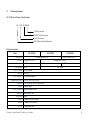
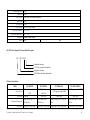
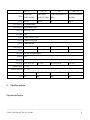
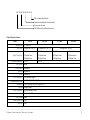
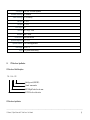
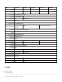
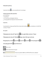
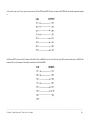
C930
Edition 9.3
Issued on November 2010
IP Device User Manual
For INC-TS/TE Series IP Camera
INS-SC/SE series IP Speed Dome
IVS-5000 Series IP Video Server
INC-MP13/20/50 Mega Pixel IP Camera
No part of this manual, including the products and software described in it, may be reproduced, transmitted, transcribed, stored in a
retrieval system, or translated into any language in any form or by any means, except documentation kept by the purchasers for
backup purposes, without the express written permission of ILDVR Digital Technology. (“ILDVR”)
Product warranty or service will not be extended if: (1) the product is repaired, modified, or altered, unless such repair, modification
of alteration is authorized in writing by ILDVR; or (2) the serial number of the product is defaced or missing.
ILDVR PROVIDES THIS MANUAL “AS IS” WITHOUT WARRANTY OF ANY KIND, EITHER EXPRESS OR IMPLIED,
INCLUDING BUT NOT LIMITED TO THE IMPLIED WARRANTIES OR CONDITIONS OF MERCHANTABILITY OR
FITNESS FOR A PARTICULAR PURPOSE. IN NO EVENT SHALL ILDVR, ITS DIRECTORS, OFFICERS, EMPLOYEES OR
AGENTS BE LIABLE FOR ANY INDIRECT, SPECIAL, INCIDENTAL, OR CONSEQUENTIAL DAMAGES (INCLUDING
DAMAGES FOR LOSS OF PROFITS, LOSS OF BUSINESS, LOSS OF USE OR DATA, INTERRUPTION OF BUSINESS AND
THE LIKE), EVEN IF ILDVR HAS BEEN ADVISED OR THE POSSIBILITY OF SUCH DAMAGES ARISING FROM ANY
DEFECT OR ERROR IN THIS MANUAL OR PRODUCT.
SPECIFICATIONS AND INFORMATION CONTAINED IN THIS MANUAL ARE FURNISHED FOR INFORMATIONAL USE
ONLY, AND ARE SUBJECT TO CHANGE AT ANY TIME WITHOUT NOTICE, AND SHOULD NOT BE CONSTRUED AS A
COMMITMENT BY ILDVR. INACCURACIES THAT MAY APPEAR IN THIS MANUAL, INCLUDING THE PRODUCTS
AND SOFTWARE DESCRIBED IN IT.
Products and corporate names appearing in this manual may or may not be registered trademarks or copyrights of their respective
companies, and are used only for identification or explanation and to the owners’ benefit, without intent to infringe.
Copyright © 2009 ILDVR DIGITAL TECHNOLOGY all rights reserved.
ILDVR Global Distribution & Service
Hungary: www.ildvr.hu
Directory
Introduction…………………………………………………………………………………………………………………………………..………1
1
Product Features and Specifications………………………………….……………………………….………………………………….…………3
1.1
Compression……………………………………………………………………………………………….…………..……………………………………….3
1.2
Network……………………………………………………………………………………………….…………..…………………………………………….3
1.3
IP Camera Specification…………………………………………………………………………….…………………………………………….….………..4
1.4
IP Speed Dome Specification…………………………………………………………………………………………………………………..….……………6
1.5
IP Video Server Specification ……………………………………………………..……………….……………………………………..………………….…8
2
Installation………………………………….……………………………….………………………………………………………………………………...9
2.1
Before Installation…………………………………………………………………………………………………………………….………………………...9
2.2
Prepare Audio Connector…………………………………………………………………………………………………………….………………………...10
2.3
IP Camera Installation………………………………………………………………………………………………….…………..………………………….10
2.4
IP Speed Dome Installation……………………………………………………………………………………………….…………..……………………….13
2.4.1
Setup PTZ Protocol and Default Baud Rate…………………………………………………………………………….…………..…………………………13
2.4.2
Setup PTZ Address……………………………………………………………………………………………………….…………..……………………….17
2.4.3
Dimension of Product……………………………………………………………………………………………….…………..…………………………….19
2.4.4
Outdoor Wall Mount……………………………………………………………………………………………….…………..………………………………20
2.4.5
Outdoor Pedant Mount……………………………………………………………………………………………….…………..……………………………21
2.4.6
Indoor Drop Ceiling Mount……………………………………………………………………………………………….…………..……………………….22
2.4.7
Indoor Recess Mount……………………………………………………………………………………………….…………..……………………………..23
2.4.8
Alarm in and Alarm out Port……………………………………………………………………………………………….…………..……………………..24
2.4.9
Overall Reviewing……………………………………………………………………………………………….…………..………………………………..25
2.5
IP Video Server Installation………………………………………………………………………………………………….……………………………….26
2.5.1
IP Server INS-5001HS……………………………………………………………………………………………….…………..…………………………..26
2.5.2
IP Server NS-5000HC/HD series………………………………………………………………………………………………….……………………..…..29
3
Network Operation…………………….……………………………………………………………….……………………………………….………..32
______________________________________________________________________________________________________________________________________________________________
IP Camera, IP Speed Dome and IP Video Server User Manual
3.1
Reset IP Address for New Network……………………………………..……………………………….……………………………………………………32
3.1.1
Use IP Capture……………………………………..……………………………….…………………………………………………………………………32
3.1.2
Use IE to Change IP…………………………………………………………………………………………………………………………………………..33
3.2
IE Web Client Operation…………………….…………………………………………………..……………………………………….……………………34
3.2.1
Login to IP Device…………………………………………………………………………………………….………………………..…..………………….34
3.2.2
Remote Live Viewing……………………………………………………………………………………………………………….…………………………37
3.2.3
Remote Setup………………………………………..………………………………………………………………………………………….……………..41
3.2.4
Remote Search and Download………………………………………………………………………………………….……………………………………..51
3.3
Video Record by Hybrid DVR Server ………………………………………………………………………………….…………………………………….53
3.4
Live Center Operation………………………………………………………………………………….……………………………………………………..53
3.5
CMS Operation………………………………………………………………………………………….…………………………………………………….53
Appendix A Pin definition of RS232………………………………………………………………………………………..……………………………54
Appendix B Pin definition of Ethernet..……………………………………..……………………………….………………………………………………………57
Appendix C Compatible SD card list…………………..……………………………….………………………………………………………………………58
______________________________________________________________________________________________________________________________________________________________
IP Camera, IP Speed Dome and IP Video Server User Manual
Introduction of IP-CCTV Solutions
Thank you for using the ILDVR® IP video surveillance system. This operation manual illustrates how to set up the hardware and software. It also
helps to explain each individual icon function and demonstrates how to use the system effectively in a stable environment. Prior to installing the
system, operators should go through this manual thoroughly. Local suppliers may support them in due course.
IP-CCTV Product Lines
Item
Product Name
Video Record Type
Reasons for choosing…
1
PC-DVR
(DVR card)
Local HDD
High resolution and high quality video images with a friendly GUI interface. It’s
convenient to operate, easy to expand the cameras, and possesses powerful
integration capabilities.
2
NetDVR
(Stand Alone)
Local HDD
Stable, with no risk of computer viruses. Requires very low maintenance.
3
IP Camera
Local SD card and network
This is the next generation product in security surveillance. This product has
everything you need, all built into one! The IP Camera is very cost effective and
incredibly easy to install
4
IP Speed Dome
Network stream
This has all the traditional high speed dome features, but overcomes the coaxial
cable distance limitation.
5
IP Video Server
Network stream
(5001HS both SD card and network)
Convert your existing analog camera to an IP camera. Use this to upgrade your
existing CCTV system to an IP-CCTV system
6
IP Matrix/TV-wall
N/A
For large scale surveillance system.
______________________________________________________________________________________________________________________________________________________________
IP Camera, IP Speed Dome and IP Video Server User Manual
[1]
______________________________________________________________________________________________________________________________________________________________
IP Camera, IP Speed Dome and IP Video Server User Manual
[2]
1
1.1
Product Features and Specifications
Compression
•
H.264 hardware compression. Every camera can be real-time hardware compressed in 25F/S (PAL) or 30F/S (NTSC) CIF resolutions independently. Support both
variable bit rate and variable frame rate.
•
•
•
•
•
•
Compressed video and audio are synchronous. You can select either mixed stream or only video stream.
Support 4CIF, DCIF, 2CIF, CIF and QCIF resolution.
Support multi-area motion detection.
Support OSD and changeable OSD position of the date and time.
Support LOGO and changeable LOGO position.
Support SD card local record, up to 64GB.
1.2
Network
•
•
•
•
•
•
•
•
•
Support TCP, UDP, RTP, Multicast for network preview.
Multi-level user management leads to high system safety. Up to 16 users.
Support PPPoE for broadband dialup.
Support PSTN for narrow band dialup.
Support dynamic DNS (DDNS)
Support Email AlarmNotification
Support remote parameters setup.
Alarm information can be sent to remote center.
Support one RS-485 interface that can be used to control pan-tilt-zoom and translucent channel input. Network control PTZ, preset, sequence and tour. Support many
kinds of PTZ protocol
•
•
•
•
•
Network record the real time stream.
Network download and playback the recorded files.
Remote upgrade the firmware.
Support bi-direction voice talk or one-way voice broadcast.
Support IE, Hybrid DVR server and Live Center to preview and record.
______________________________________________________________________________________________________________________________________________________________
IP Camera, IP Speed Dome and IP Video Server User Manual
[3]
1.3
IP Camera Specification
INC-TS/TE Series IP Camera Model Description
INC – TS/TE 288/38 NI/NH
CCD filter code name
480/420 TV-Line code number
Sony CCD code name
ILDVR Network Camera abbreviation
IP Camera Specification
Model
INC-TS38NH
1/3" Sony Super HAD CCD
Image Sensor
Resolution
Minimum Illumination
White Balance
B. L. C. Function
Auto Iris
Video Compression
Compression Resolution
Frame Rate
Bit Rate
Audio Compression
Stream Type
Dual Stream
Audio in
Audio out
Video Out
INC-TS288NI
0.4Mega Pixels / 420 TVL
0.5 LUX
INC-TE288NI
1/3" Sony EXview HAD CCD
0.4Mega Pixels / 480 TVL
0.01 LUX
AUTO
ON / OFF Optional
Video / DC
H.264 (Hardware support)
D1 (4CIF), 2CIF, DCIF, CIF, QCIF
1/16 to 25 fps (PAL) or 1/16 to 30 fps (NTSC)
32Kbps to 2Mbps
OggVorbis Standard, 16kbps
Video & Audio / Video
Support
1 Channel (2.0 to 2.4Vp-p, 1kΩ)
1 Channel (Line Level, 600Ω)
1 Channel analog video
0.001 LUX
ATW / MWB
______________________________________________________________________________________________________________________________________________________________
IP Camera, IP Speed Dome and IP Video Server User Manual
[4]
Alarm In (Data In)
1 port
Relay out
1 port
Network port
1 RJ45 10M / 100M Auto-Negotiation
RS485 port
1 port
SD Card slot
1 port
Power Supply
Operation Humidity
Operation Temperature
Dimension
Weight
DC 12V(±20%) / 350mA
10% ~ 90%
-10°C ~ 50°C
100mm x 70mm x 60mm
400g
450g
INC-MP Series Megapixel IP Camera Model Description
INC – MP 13/20/50 V
Vandalproof housing
1.3/2.0/5.0 mega pixel code number
Megapixel code name
ILDVR Network Camera abbreviation
IP Camera Specification
Model
Image Sensor
Resolution
Minimum Illumination
Frame Rate
INC-MP13CD
INC-MP20CD
INC-MP20A/20V
1/3" Sony Progressive scan
CCD
1/1.8" Sony Progressive
scan CCD
1/3" Progressive scan CMOS
1280*960
1600*1200
Color: 0.1Lux @ F1.2 /
B/W 0.01 Lux
Color: 0.5Lux @ F1.2 /
B/W 0.05 Lux
15fps(1280 × 960), 25fps
12fps (1600 × 1200), 25fps
1600*1200
Color: 0.5Lux @ F1.2 / B/W 0.05
Lux
15fps (1600 × 1200), 25fps (1280 ×
INC-MP50N/MP50V
1/2.5" Progressive scan CMOS
2560*1920
Color: 0.5Lux @ F1.2 / B/W
0.05 Lux
12fps (2560 × 1920), 25fps
______________________________________________________________________________________________________________________________________________________________
IP Camera, IP Speed Dome and IP Video Server User Manual
[5]
(1280 × 720
Bit Rate
Auto Iris
32Kbps to 16Mbps adjustable.
Max. 16Mbps
Video / DC
Video / DC
No
Video / DC
1
1
4
3
AC24V / DC12V/ PoE
DC12V / PoE
145mm x 66mm x 57mm
155mm x 78mm x 68mm
450g
980g
OggVorbis Standard, 16kbps
Stream Type
Video & Audio / Video
Dual Stream
Support
1 Channel (2.0 to 2.4Vp-p, 1kΩ)
Audio out
1 Channel (Line Level, 600Ω)
Video Out
1 Channel analog video
Network port
RS485 port
SD Card slot
Power Supply
Operation Humidity
Operation Temperature
Dimension
Weight
1.4
32Kbps to 8Mbps adjustable. Max.
8Mbps
Audio Compression
Relay out
(1280 × 720)
32Kbps to 16Mbps
adjustable. Max. 16Mbps
H.264 (Hardware support)
Alarm In (Data In)
720)
32Kbps to 8Mbps
adjustable. Max. 8Mbps
Video Compression
Audio in
(1280 × 720)
4
1
3
1 RJ45 10M / 100M Auto-Negotiation
1 port
1 port
AC24V / DC12V/ PoE
DC12V / PoE
10% ~ 90%
-10°C ~ 50°C
145mm x 66mm x 57mm
155mm x 78mm x 68mm
450g
980g
1
IP Speed Dome Specification
IP Speed Dome Model Description
______________________________________________________________________________________________________________________________________________________________
IP Camera, IP Speed Dome and IP Video Server User Manual
[6]
INS –SC(SE) 220/230/300/350 -B
B/W code name (Day & Night)
Optical Zoom and Digital Zoom code number
Series product line code
ILDVR Network Speed Dome abbreviation
IP Speed Dome Specification
Model
INS-220
Image Sensor
Resolution
Digital Zoom Ratio
Minimum Illumination
Sync System
0.4Mega Pixels / 480 TVL
F 3.6~82.8mm
23X Optical Zoom
10X Digital Zoom
1.0 LUX
0.01 LUX
Auto/Manual
Focal
Auto/Manual
Bit Rate
Audio Compression
INS-350B
0.4Mega Pixels / 480 TVL
F 3.4~102mm
30X Optical Zoom
12X Digital Zoom
F 3.4~119mm
35X Optical Zoom
12X Digital Zoom
Internal
Aperture
Frame Rate
0.4Mega Pixels / 540 TVL
F 3.9~85.8mm
22X Optical Zoom
10X Digital Zoom
Auto/Manual
Compression Resolution
INS-300B
1/4" Sony CCD
White Balance
Video Compression
INS-230B
H.264 (Hardware support)
D1 (4CIF), 2CIF, DCIF, CIF, QCIF
1/16 to 25 fps (PAL) or 1/16 to 30 fps (NTSC)
32Kbps to 2Mbps
OggVorbis Standard, 16kbps
Stream Type
Video & Audio / Video
Dual Stream
Support
Alarm In (Data In)
4 port
Relay out
1 port
______________________________________________________________________________________________________________________________________________________________
IP Camera, IP Speed Dome and IP Video Server User Manual
[7]
Network port
Horizontal Scan Range
Vertical Scan Range
360° continuous
90° (180° auto-flip)
Pan Speed
0.8°~300°/s
Tilt Speed
0.8°~120°/s
Preset Targets
Video Out
Installation
Fan and Heater
Operation Temperature
Operation Humidity
Power Supply
Weight
1.5
1 RJ45 10M / 100M Auto-Negotiation
128
BNC 1.0Vp-p / 75ohm
Indoor / Outdoor
Fan & heater auto-start
-35°C~+55°C
10-85% without agglomeration
AC24V /1.7A
2.0 Kg (without outdoor housing)
IP Video Server Specification
IP Video Server Model Description
IVS – 5 0 0 x H X
Model type code (HS/HC/HD)
Channel / camera number
ILDVR Digital Product Line code name
ILDVR Video Server abbreviation
IP Video Server Specification
______________________________________________________________________________________________________________________________________________________________
IP Camera, IP Speed Dome and IP Video Server User Manual
[8]
Model
Video Input
Audio Input
Audio Output
Video Out
Audio Intercom
Video Format
Video Compression
Compression Resolution
Frame Rate
Bit Rate
Audio Compression
Stream Type
Dual Stream
Alarm In (Data In)
Relay out
Network port
RS485 port
RS232 port
Power Supply
Operation Humidity
Operation Temperature
Dimension
Weight
2
IVS-5001HS
IVS-5002HC
IVS-5004HC
1
2
4
1
2
4
1 Ch (Linear Electrical Level, 600Ω)
1 Channel analog video N/A
N/A
1 Channel (2Vp-p, 1kΩ)
PAL / NTSC
H.264 (Hardware support)
D1 (4CIF), 2CIF, DCIF, CIF, QCIF
CIF, QCIF
1/16 to 25 fps (PAL) or 1/16 to 30 fps (NTSC)
32Kbps to 2Mbps
OggVorbis Standard, 16kbps
Video & Audio / Video
Support
1 port
4
1 port
2
1 RJ45 10M / 100M Auto-Negotiation
1 port
N/A
1
DC 12V / 250mA
DC 12V / 600mA
10% ~ 90%
-10°C ~ 50°C
81mm x 91mm x 41mm 202mm x 137mm x 43mm
320g
1500g
IVS-5001HD
1
1
IVS-5002HD
2
2
D1 (4CIF), 2CIF, DCIF, CIF, QCIF
2
1
Installation
2.1 Before Installation
______________________________________________________________________________________________________________________________________________________________
IP Camera, IP Speed Dome and IP Video Server User Manual
[9]
•
•
•
•
•
After Opening the packing box, please check carefully to confirm that the goods in it are consistent with list
Please read user's manual carefully before installation
Please power-off all related equipments before installation
Please check the voltage of power supply to avoid voltage mismatch
Installation environmental: Do not use it under humidity and high temperature, to keep ventilation to vent freely, avoid to setup in the vibration surroundings.
2.2 Prepare Audio Connector
The IP camera and IP video server use standard 3.5mm Stereo Jack connector but the audio type is mono audio, please refer to following picture to make your
audio connector.
______________________________________________________________________________________________________________________________________________________________
IP Camera, IP Speed Dome and IP Video Server User Manual
[10]
2.3 IP Camera Install
______________________________________________________________________________________________________________________________________________________________
IP Camera, IP Speed Dome and IP Video Server User Manual
[11]
Item
Name
Description
1
Lens Mount
CS-mount lens
2
Back Focus Lock Screw
After adjusting the CS ring, turn this screw with a screw driver to lock the back focus.
3
DIP Switch
Camera function switches, see next page.
4
B&R Color Adjustment
In MWB mode, press button to adjust blue or red color
5
Power LED
Side LED power on indicates CCD module working status. Rear LED power on indicates network module
working status.
6
Lens connector and Iris level adjustment
When using DC servo lens, slowly turn the LEVEL potentiometer until the picture appears to be perfect
7
Power Connector
DC 12V power connector
8
RJ 45 Connector
Network Connector
9
Audio in & Audio out Connector
Microphone and Speaker connector
10
SD Card Slot
Up to 64GB SDHC SD card
11
Video Out
Output analog video
12
RS485 Connector
Connect to PTZ RS485 port
13
Alarm In Connector
Switch-type signal input
14
Alarm Out Connector
Switch-type signal output
16
Tripod Adapter
The tripod adapter can be attached to either the top or the bottom of the camera housing
Installation tips:
If you are looking at network video to adjust the focus of IP camera’s lens, due to the network delay, it is difficult to get perfect picture quality. Please use an analog
monitor to connect the Analog Video Out (Port 11) then get around the video delay.
______________________________________________________________________________________________________________________________________________________________
IP Camera, IP Speed Dome and IP Video Server User Manual
[12]
Items
1
2
3
4
5
6
7
8
9
Name
IR
INT
L.L.
AI
AES
D&N
ATW
MWB
Turbo AGC
Description
Set IR cut for the cameras model name ending with NI, for example “TE288NI”
Set Internal Synchronize as default
Line Lock (not available)
Set Auto Iris mode when using automatic lens
Set Auto Electric Shutter mode when using manual lens
Turn on Day & night function
Set Auto Trace White Balance mode
Set Manual White Balance mode
Set Auto Gain Control mode
2.4 IP Speed Dome Install
2.4.1
Setup PTZ Protocol and Default Baud Rate
For your attention, your IP speed dome hardware jumper switch settings of PTZ protocol, Baud Rate and Address must be matching the PTZ tab configuration of
IP Camera Setup in Hybrid Server program and Live Center program, see next picture or refer to Mnual-1 and Manual-4 for more information.
______________________________________________________________________________________________________________________________________________________________
IP Camera, IP Speed Dome and IP Video Server User Manual
[13]
______________________________________________________________________________________________________________________________________________________________
IP Camera, IP Speed Dome and IP Video Server User Manual
[14]
SW 1
SW2
NO
NO
1
2
3
4
5
6 7 8 9 10
Speed Dome Address Select
SW2
1
2
3
4
5
6
Protocol Select
SW1
Vertical View
Connector Pin
______________________________________________________________________________________________________________________________________________________________
IP Camera, IP Speed Dome and IP Video Server User Manual
[15]
As shown in above figure, SW1 is used to set PTZ protocol of communication and the baud rate. DIP-1 to DIP-4 of SW1 is used to set protocol. Up to 16 protocols can be
chosen according your system capacity. The following table shows DIP switch settings for each protocol. The default PTZ Protocol is PELCO-D. You usually don’t need
change this setting.
DIP status
Normal Baud Rate
Protocols
DIP-1
DIP-2
DIP-3
DIP-4
DIP-5
DIP-6
SAMSUNG
ON
OFF
OFF
OFF
OFF
ON
B01
ON
OFF
OFF
OFF
OFF
ON
NEON
ON
OFF
OFF
OFF
OFF
ON
SANTACHI
OFF
ON
OFF
OFF
OFF
ON
PELCO-D
ON
ON
OFF
OFF
OFF
OFF
ON
OFF
OFF
OFF
ON
OFF
OFF
ON
PELCO-P/4800
PELCO-P/9600
PANASONIC
ON
OFF
ON
OFF
OFF
ON
LONGCOMITY
OFF
ON
ON
OFF
OFF
ON
HUNDA600
ON
ON
ON
OFF
OFF
ON
LILIN
OFF
OFF
OFF
ON
OFF
ON
VICON
ON
OFF
OFF
ON
ON
OFF
MOLYNX
OFF
ON
OFF
ON
OFF
ON
KALATEL
ON
ON
OFF
ON
ON
OFF
VCL
OFF
OFF
ON
ON
OFF
ON
Reserved
ON
OFF
ON
ON
OFF
ON
ALEC
OFF
ON
ON
ON
OFF
ON
ULTRAK
ON
ON
ON
ON
OFF
ON
______________________________________________________________________________________________________________________________________________________________
IP Camera, IP Speed Dome and IP Video Server User Manual
[16]
DIP-5 and DIP-6 of SW1 are used to set the baud rate. Up to 4 different baud rates can be set.
Baud Rate of Communication
Setup of Baud Rate
DIP-1
DIP-2
DIP-3
DIP-4
DIP-5
DIP-6
2400 bps
OFF
OFF
4800 bps
ON
OFF
9600 bps
OFF
ON
19200 bps
ON
ON
Here are some examples of DIP switch SW1:
ON
PANASONIC/9600Bps
NEON /9600Bps
1
2
3
4
5
6
ON
1
2
3
4
5
6
1
2
3
4
5
6
1
2
3
4
5
6
1
2
3
4
5
6
ON
KALATEL /4800Bps
PELCO-D/ 2400Bps
1
2
3
4
5
6
ON
ON
PELCO-P/4800Bps
ALEC /9600Bps
1
2
3
4
5
6
ON
ON
PELCO -P/9600Bps
Ultrak /9600Bps
1
2.4.2
ON
2
3
4
5
6
Setup PTZ Address
As shown in above figure, SW2 is used to set address of IP dome camera from 1 – 1023. The jumper switches from DIP-10 to DIP-1 are equivalent to a 10-bit binary
______________________________________________________________________________________________________________________________________________________________
IP Camera, IP Speed Dome and IP Video Server User Manual
[17]
digital. DIP-10 is MSB while DIP-1 is LSB. The state “ON” of each bit means 1 while “OFF” means 0. Following table shows DIP switch settings for some addresses.
The default PTZ address is #1. You usually don’t need change this setting.
DIP Switch Settings
Dome Address
DIP-1
DIP-2
DIP-3
DIP-4
DIP-5
DIP-6
DIP-7
DIP-8
DIP-9
DIP-10
1
ON
OFF
OFF
OFF
OFF
OFF
OFF
OFF
OFF
OFF
2
OFF
ON
OFF
OFF
OFF
OFF
OFF
OFF
OFF
OFF
3
ON
ON
OFF
OFF
OFF
OFF
OFF
OFF
OFF
OFF
4
OFF
OFF
ON
OFF
OFF
OFF
OFF
OFF
OFF
OFF
5
ON
OFF
ON
OFF
OFF
OFF
OFF
OFF
OFF
OFF
6
OFF
ON
ON
OFF
OFF
OFF
OFF
OFF
OFF
7
ON
ON
ON
OFF
OFF
OFF
OFF
OFF
OFF
OFF
8
OFF
OFF
OFF
ON
OFF
OFF
OFF
OFF
OFF
OFF
9
ON
OFF
OFF
ON
OFF
OFF
OFF
OFF
OFF
OFF
10
OFF
ON
OFF
ON
OFF
OFF
OFF
OFF
OFF
OFF
11
ON
ON
OFF
ON
OFF
OFF
OFF
OFF
OFF
OFF
12
OFF
OFF
ON
ON
OFF
OFF
OFF
OFF
OFF
OFF
13
ON
OFF
ON
ON
OFF
OFF
OFF
OFF
OFF
OFF
14
OFF
ON
ON
ON
OFF
OFF
OFF
OFF
OFF
OFF
15
ON
ON
ON
ON
OFF
OFF
OFF
OFF
OFF
OFF
16
OFF
OFF
OFF
OFF
ON
OFF
OFF
OFF
OFF
OFF
17
ON
OFF
OFF
OFF
ON
OFF
OFF
OFF
OFF
OFF
18
OFF
ON
OFF
OFF
ON
OFF
OFF
OFF
OFF
OFF
…
…
…
…
…
…
…
…
…
…
…
1023
ON
ON
ON
ON
ON
ON
ON
ON
ON
ON
Here are some examples of DIP switch SW2:
______________________________________________________________________________________________________________________________________________________________
IP Camera, IP Speed Dome and IP Video Server User Manual
[18]
ON
ON
1 2 3 4
5
6 7 8
9 10
1 2 3 4
5
6 7 8
9 10
1 2 3 4
5
6 7 8
9 10
Speed Dome Address=1
Speed Dome Address=2
Speed Dome Address=3
ON
ON
ON
1 2 3 4
5
6 7 8
9 10
Speed Dome Address=4
2.4.3
ON
1 2 3 4
5
6 7 8
9 10
Speed Dome Address=18
1 2 3 4
5
6 7 8
9 10
Speed Dome Address=1023
Dimension of Product
The measure unit in following illustration figures is by millimeter, for example, 350 means 350 mm.
SC-208V Outdoor Housing
______________________________________________________________________________________________________________________________________________________________
IP Camera, IP Speed Dome and IP Video Server User Manual
[19]
2.4.4
Outdoor Wall Mount
You need SC-208V Outdoor Housing and B18 Bracket to complete the Wall Mount installation. Please complete waterproof processing when install the speed dome
housing.
SC-208V Outdoor Housing + B18 Bracket
______________________________________________________________________________________________________________________________________________________________
IP Camera, IP Speed Dome and IP Video Server User Manual
[20]
Installation Steps (take wall mounting as example)
•
•
•
•
•
Unpack the carton and carefully take out the dome camera and its attachments.
Bring through and take out system cables from the bracket
Fix the housing on the bracket and rotate clockwise until it is firmly fixed
Drill 4 holes on the wall according the measure size of bracket
Fix the bracket on the wall
Other adapters suitable for B18 Bracket
B20 Pole Mount Adapter
2.4.5
B21 Outside Corner Adapter
B22 Pole Mount Adapter
Outdoor pendant Mount
You need SC-208V Outdoor Housing and B23 Bracket (10cm length) or B24 Bracket (30cm length) to complete the Pendant Mount installation. We offer customized service for
any length of bracket to meet your project requirement. Please contact your dealer for more information.
Please complete waterproof processing when install the speed dome housing.
______________________________________________________________________________________________________________________________________________________________
IP Camera, IP Speed Dome and IP Video Server User Manual
[21]
SC-208V outdoor housing + B23 bracket
2.4.6
Indoor Drop Ceiling Mount
You need B10 Bracket and the dome pedestal to complete the Drop Ceiling Mount installation.
For your attention, the dome body of indoor package is different from the dome body of outdoor package. The aluminum dome body for indoor is designed as intact
cylinder and came with a vitreous cover. The aluminum dome body for outdoor is designed as cooling cylinder and came without a vitreous cover.
______________________________________________________________________________________________________________________________________________________________
IP Camera, IP Speed Dome and IP Video Server User Manual
[22]
B10 Bracket
Indoor dome body
Dome Pedestal
Indoor vitreous cover
2.4.7
Indoor Recess Mount
You need B15 Bracket and the dome pedestal to complete the Indoor Recess Mount installation.
B15 Bracket
______________________________________________________________________________________________________________________________________________________________
IP Camera, IP Speed Dome and IP Video Server User Manual
[23]
2.4.8
Alarm In and Alarm Out Port
For your attention, Alarm Input signal type must be Switch-type signal, any other input signal might damage IP Speed Dome. The built-in alarm system of IP Speed Dome
only triggers PTZ Presets No. 29 to No. 32. It has no relationship with alarm-in/alarm-out of DVR system. When multiple alarm-in trigger, speed dome will respond one
by one in sequence of two seconds interval. Once the IP speed dome has alarm-in trigger, it will not respond to other operation such as “Scanning”, “Tour”, “Remember
Tracking” etc.
ALM-4 : Channel 4 collector alarm input :1
ALM-3 : Channel 3 collector alarm input :2
ALM-2 : Channel 2 collector alarm input :3
ALM-1 : Channel 1 collector alarm input :4
GND : Common collector alarm input : 5
COM : Common collector alarm output :6
OUTPUT : Alarm output A
OUTPUT : Alarm output B
D3
1:AC24V IN
2:AC24V IN
1
1
D2 : connect fan/heater
(AC24V)
RJ45 Connect
Dome Pedestal
______________________________________________________________________________________________________________________________________________________________
IP Camera, IP Speed Dome and IP Video Server User Manual
[24]
Alarm input
ALM-1
ALM-2 ALM-3 ALM-4
Alarm output
No. 1
No. 2
No. 3
No. 4
2.4.9
,
,
,
,
call No. 29 preset
call No. 30 preset
call No. 31 preset
call No. 32 preset
OUTPUT B
OUTPUT A
GND
C OM
ALM -1
ALM-2
ALM- 3
ALM-4
D3
Alarm In trigger
Alarm In trigger
Alarm In trigger
Alarm In trigger
Overall Reviewing
Before you power on the IP speed dome camera, please do an overall reviewing. Otherwise please refer to following figure for troubleshooting.
•
•
•
•
Have you taken out all package protection materials under the indoor/outdoor vitreous cover?
Have you taken out the indoor vitreous cover if you install outdoor housing? (Otherwise it will reduce the picture quality)
Did you set up the dome and housing firmly?
Are you sure the Protocol, Address and Baud Rate settings match your DVR program configuration?
Disassembling steps:
•
Rotate the vitreous cover dome counterclockwise and take it out.
•
Push the ball upward to the end and rotate counterclockwise until it is loose then take it out.
Assembling steps:
•
Aim at the “MARK” on the ball at the notch on the pedestal, push the ball upward to the end and rotate clockwise until it is clicked.
•
Mount the vitreous cover by rotating it clockwise at last.
______________________________________________________________________________________________________________________________________________________________
IP Camera, IP Speed Dome and IP Video Server User Manual
[25]
Mark
Unfix
Fix
Indoor vitreous cover
Unfix
Fix
Outdoor vitreous cover
2.5
2.5.1
IP Video Server Install
IP Server IVS-5001HS
For your attention, if you connect analog speed dome to IVS-5001HS video server, please refer to above section 2.4 to set analog speed dome PTZ protocol=PECLO-D,
Baud Rate=2400 and Address=1. The speed dome hardware jumper switch settings of PTZ protocol, Baud Rate and Address must be matching the PTZ tab
configuration of IP Camera Setup in Hybrid Server program and Live Center program
______________________________________________________________________________________________________________________________________________________________
IP Camera, IP Speed Dome and IP Video Server User Manual
[26]
Item
Name
Description
5
Power LED
LED power on indicates network module working status.
7
Power Connector
DC 12V power connector
8
RJ 45 Connector
Network Connector
9
Audio in & Audio out Connector
Microphone and Speaker connector
10
SD Card Slot
Up to 64GB SDHC SD card
11
Video Out
Output analog video
12
RS485 Connector
Connect to PTZ RS485 port
13
Alarm In Connector
Switch-type signal input
14
Alarm Out Connector
Switch-type signal output
15
BNC Connector
Analog Video In, connect to camera video out
______________________________________________________________________________________________________________________________________________________________
IP Camera, IP Speed Dome and IP Video Server User Manual
[27]
______________________________________________________________________________________________________________________________________________________________
IP Camera, IP Speed Dome and IP Video Server User Manual
[28]
2.5.2
IP Server IVS-5000HC/HD Series
Item
Name
Description
1
Power LED
LED power on indicates server working status.
2
Link LED
LED power on indicates network working status
3
Tx/Rx data LED
LED power on indicates RS232/RS485 data transmit working status.
4
Power Connector
DC 12V power connector
5
UTP Connector
RJ 45 Network Connector
6
Alarm In Connector
4-port alarm input
7
Alarm Out Connector
2-port relay output
______________________________________________________________________________________________________________________________________________________________
IP Camera, IP Speed Dome and IP Video Server User Manual
[29]
8
RS232 Connector
Standard RS-232 serial port RJ45 socket, connect to computer COM port for maintenance
9
RS485 Connector
Standard RS-485 serial port RJ45 socket. Connect to PTZ RS485 port
10
Audio In
4-BNC audio connector for audio recording
11
Video In
4-BNC video connector for video recording
12
Audio Line In
Microphone line in for Remote Chat (VoIP)
13
Audio out Connector
Speaker connector
14
GND Connector
Ground Connection
The pin definition of RS-485 Serial interface
Please prepare one cable with a RJ45 connecter, Line-1 connect to Analog speed dome RS485+ port and Line-2 connect to analog speed dome RS485- port.
______________________________________________________________________________________________________________________________________________________________
IP Camera, IP Speed Dome and IP Video Server User Manual
[30]
______________________________________________________________________________________________________________________________________________________________
IP Camera, IP Speed Dome and IP Video Server User Manual
[31]
For your attention, if you connect analog speed dome to IVS-5002HC/5004HC/5002HD video server, please refer to above section 2.4 to set the analog speed dome
protocol=PECLO-D, Baud Rate=2400 and Address=1, 2, 3, 4 respectively. The speed dome hardware jumper switch settings of PTZ protocol, Baud Rate and Address
must be matching the PTZ tab configuration of IP Camera Setup in Hybrid Server program and Live Center program
3
Network Operation
Every IP device has built-in web server, users can easily remote access it by Internet Explorer to perform remote preview, remote control PTZ, remote playback, remote
setup and download archive video, etc. But IE web client is limited to point-to-point connection. That means you can connect only one IP device in one IE window. This
kind of solution is not suitable for multiple sites surveillance system. ILDVR offers 2 higher levels of software solutions for complicated network surveillance system.
Please refer to Live Center solution and CMS solution for more information.
3.1 Reset IP address for new Network
Before you build up the IP surveillance system, please plan a network layout for your IP video device. Every IP device must be configured a static IP address. You have 2
ways to change the default factory IP address to your local network IP address.
3.1.1
Use IP Capture
If you don’t know the original IP address of your IP device. Please choose IP Capture to do the job. To use IP Capture software to change IP address, you should install
the IPCapture.exe program firstly. You can find this utility software in the sub-folder of Utilities of your software CD. After you finish installation, there is a shortcut icon
“Sadp” on desktop, double click it to run the program.
Tips:
•
•
•
If your computer OS is Windows Vista, please select “Run as administrator” from right-click menu to run “Sadp”.
Your IP device and the computer should be in same network segment.
To modify the IP address you need “admin” user rights. If you forget the admin password, please refer to Appendix D to reset the IP device.
In “SADP” interface, click an IP device from left table. This IP address information will show in right table. Click “modify” button to highlight the input box then input
new IP information. After finish, click “save” button. See the picture in next page
______________________________________________________________________________________________________________________________________________________________
IP Camera, IP Speed Dome and IP Video Server User Manual
[32]
3.1.2
Use IE to change IP
If you already get acknowledge the original IP address of your IP device, please go ahead to login the IP device by Internet Explorer and go to Remote Setup page to
change IP address, refer to section 3.2.3.
______________________________________________________________________________________________________________________________________________________________
IP Camera, IP Speed Dome and IP Video Server User Manual
[33]
3.2 IE web client operation
3.2.1
Log in
Run Internet Explorer and input the IP address in the IE address box. Press “Enter” and a security warning will appear after connecting with the DVR server. This
warning is the Active X control that needs to be downloaded in order to use this feature. Click “Yes” to continue.
If you have correctly configured the IP Device with DNS/DDNS, you can also input the IP device’s domain name and web listening port in the IE address box.
Windows XP/VISTA security settings prevent users from installing unsigned ActiveX controls. You must turn off Windows firewall and change IE security
settings to enable “Download of unsigned ActiveX controls”. After it’s done installing the ILDVR web client, please restore your IE security setting back to its
original settings. See the following 2 diagrams.
______________________________________________________________________________________________________________________________________________________________
IP Camera, IP Speed Dome and IP Video Server User Manual
[34]
______________________________________________________________________________________________________________________________________________________________
IP Camera, IP Speed Dome and IP Video Server User Manual
[35]
When the following dialog interface appears, click OK button to install ActiveX controls.
After finish installation of ActiveX controls, the following web client login interface will appear. Input correct User name, Password and TCP port. Click “Login” button.
For your attention
Different generations of products may have different interface
but most of parameters and their meanings are consistent.
______________________________________________________________________________________________________________________________________________________________
IP Camera, IP Speed Dome and IP Video Server User Manual
[36]
3.2.2
Remote Live Viewing
Main interface
______________________________________________________________________________________________________________________________________________________________
IP Camera, IP Speed Dome and IP Video Server User Manual
[37]
Control Buttons
All channels connect button.
All channels disconnect button
Capture image button
Manual record button, the video save in local disk, default save directory is D:\webrecord\. To play the saved video, you must use the utility Player.exe
No record button.
Start remote talk button.
Logout button
Stop remote talk button
Login button
Live viewing button
Remote playback button
Remote setup button
Remote log search button
Split mode shift button
PTZ control button, center is auto.
Preset control button, input preset number then click button
Wiper on/off button
to call it. Click button
to save it.
Light on/off button
______________________________________________________________________________________________________________________________________________________________
IP Camera, IP Speed Dome and IP Video Server User Manual
[38]
Lens control button
From up to down, adjust voice volume, brightness, contrast, tone and saturation.
Click it to restore default
Display computer CPU info, date & time and login ID information.
Display video server device name and channel connection information. You
can double click the channel icon to get connection
From Right-click menu, select main-stream or sub-stream, open audio spy.
Connecting operation steps:
•
•
Click (select) one blank window that you want view remote video
Double click channel icon to display that camera.
______________________________________________________________________________________________________________________________________________________________
IP Camera, IP Speed Dome and IP Video Server User Manual
[39]
Or click button
to get all channels connecting.
Remote Live Preview
______________________________________________________________________________________________________________________________________________________________
IP Camera, IP Speed Dome and IP Video Server User Manual
[40]
3.2.3
Remote Setup
In the web client main interface, click
button to enter Remote Setup interface. There are 7 pages in total. In these pages you can
change system parameters, reboot IP Device, load default parameters, etc.
Server Configuration
From this page you can read IP device serial
number to register license, check system firmware
version for upgrade information.
You can modify device name, device ID and
network parameters.
Set “Cycle record” to “YES” will overwrite the SD
card when it is full.
Set “Enable scaler” to “ON” will enable “Video
Zoom In” function in network client software.
______________________________________________________________________________________________________________________________________________________________
IP Camera, IP Speed Dome and IP Video Server User Manual
[41]
Channel Configuration
In this page you can setup camera parameters
such as OSD, image quality, stream type,
frame rate and bit rate.
If you have SD card to record video locally,
please go to “Others” page to format the SD
card firstly then come back to setup recording
Schedule in this page.
If you use Motion Detect function, please
click “Area setup” to bring up “Set motion
detect areas” interface in next page.
______________________________________________________________________________________________________________________________________________________________
IP Camera, IP Speed Dome and IP Video Server User Manual
[42]
Set motion detect areas
Setup motion detect areas and its sensitivity
in this page.
Press “Ctrl” then drag &drop your mouse to
draw the motion detect area
______________________________________________________________________________________________________________________________________________________________
IP Camera, IP Speed Dome and IP Video Server User Manual
[43]
Network configuration
In this page, setup network parameter for the IP
device to login other server. The IP device works
as client mode.
Click “E-mail Configuration” button to bring up
“E-mail Configuration” interface in next page.
______________________________________________________________________________________________________________________________________________________________
IP Camera, IP Speed Dome and IP Video Server User Manual
[44]
Email Configuration
If you implement email alarm function
please setup Email parameters from
this page.
______________________________________________________________________________________________________________________________________________________________
IP Camera, IP Speed Dome and IP Video Server User Manual
[45]
COM Configuration
Modify RS232 communication parameters
Setup PTZ protocol, baud rate and address
If you are using Hybrid server or Live Center
program to manage this IP device, please set
PTZ parameters carefully. Refer to section 2.4
for more information.
______________________________________________________________________________________________________________________________________________________________
IP Camera, IP Speed Dome and IP Video Server User Manual
[46]
Alarm Configuration
Setup external alarm input parameters, relay out
parameters and Exception alarm settings.
For your attention, if you continuously hear BEEP
sound from any IP device, the beep sound might
come from “Audible warning” for “Exception
type” error of “Hard disk error”. For example you
don’t have SD card installed in the IP device.
To stop the beep warning, just check off the
“Audible warning”
______________________________________________________________________________________________________________________________________________________________
IP Camera, IP Speed Dome and IP Video Server User Manual
[47]
User Configuration
User name, password and user right management.
Right-click a user ID, choose “Modify” from
right-click menu. You can modify the user name,
password and operation rights. After finishing,
click “Save” button.
The “Administrator” default ID is admin, you
cannot change this name but you can change its
password.
______________________________________________________________________________________________________________________________________________________________
IP Camera, IP Speed Dome and IP Video Server User Manual
[48]
Transaction Configuration
The features in this page are only useful for
IL-6000HA series ATM/POS NetDVR.
______________________________________________________________________________________________________________________________________________________________
IP Camera, IP Speed Dome and IP Video Server User Manual
[49]
Others
This is the system utility. In this page you
can upgrade system software and format
SD card.
New SD card must format firstly before
recording any video.
______________________________________________________________________________________________________________________________________________________________
IP Camera, IP Speed Dome and IP Video Server User Manual
[50]
3.2.4
Remote Search and download
______________________________________________________________________________________________________________________________________________________________
IP Camera, IP Speed Dome and IP Video Server User Manual
[51]
Remote playback operation steps
In main interface click button
to enter into remote playback interface. See as above diagram.
Select target search camera in the camera list box
•
•
•
•
Select record file type
Select archive time
Click “Search” button to list all matching files in file list box
Select target playback file then click play button. Or double click the selected file.
Download Video
In remote playback interface, selecting a target file from file list box in the right, then click download button
save directory is C:\Download\
to save download and save it to local disk. Default
Other operations
While playing back archive video, click “Capture” button
While playing back archive video, click “Clip” button
During playing back, you can click
increase playing speed, and click
to pause, click
to take a snapshot. Default save directory is C:\Capture\
to begin a video clip. Click it again to end video clip.
to play, click
to stop, click
to decrease playing speed, click
to
to play in frame one by one.
Adjust voice volume
Switch one channel and 4 channel viewing mode.
This feature is only available to IL6000HA series ATM/POS NetDVR. Search video by bankcard info.
______________________________________________________________________________________________________________________________________________________________
IP Camera, IP Speed Dome and IP Video Server User Manual
[52]
3.3
Video Record by Hybrid DVR Server
Please refer to Hybrid DVR Server and Live Center User Manual
3.4
Live Center Operation
Please refer to Hybrid DVR Server and Live Center User Manual
3.5
CMS Operation
Please refer to Central Management System User Manual
______________________________________________________________________________________________________________________________________________________________
IP Camera, IP Speed Dome and IP Video Server User Manual
[53]
Appendix A:
The pin definition of RS-232 Serial interface
The IVS-5000HC/HD video server has one RS232 standard serial interface, with RJ-45 connector. Its pin definition is as follows (‘I’ means input, and ‘O’ means output):
(1) When the RS232 interface of the IVS video server connects with the DTE equipment, one end of the cable is the 8-pin RJ45 connector (to IVS) and the other of the
cable is the DB25 female connector (to DTE). Below is the description of the internal connection between RJ45 and DB25.
______________________________________________________________________________________________________________________________________________________________
IP Camera, IP Speed Dome and IP Video Server User Manual
[54]
(2) 25-pin to 9-pin converter’s internal connection is like this:
______________________________________________________________________________________________________________________________________________________________
IP Camera, IP Speed Dome and IP Video Server User Manual
[55]
(3) If you don’t want to use 25-pin to 9-pin convertor to connect IVS and DTE through RS232 interface, you must use RJ45-DB9 cable. Its internal connection description
is:
(4) When the RS232 interface of the IVS connects with the DCE (such as MODEM), one end of the cable is the 8-pin RJ45 connector and the other is the DB25 male
connector. Below is the description of the internal connection between RJ45 and DB25:
______________________________________________________________________________________________________________________________________________________________
IP Camera, IP Speed Dome and IP Video Server User Manual
[56]
Appendix B:
The pin definition of Ethernet interface (UTP port)
(1) PIN definition of the direct network cable connecting IVS and HUB:
(2) PIN definition of the cross network cable connecting IVS and host PC:
______________________________________________________________________________________________________________________________________________________________
IP Camera, IP Speed Dome and IP Video Server User Manual
[57]
Appendix C:
Compatible SD card list
The following SD cards have been tested with ILDVR IP Camera to ensure compatibility.
•
•
•
•
•
•
A-Data 4GB, 16GB
Apacer 4GB, 8GB
KINGMAX 4GB, 8GB
Kingston 4GB, 8GB, 32GB
SanDisk 4GB, 8GB
Transcend 4GB, 8GB, 16GB
______________________________________________________________________________________________________________________________________________________________
IP Camera, IP Speed Dome and IP Video Server User Manual
[58]
Technical Support Information
Please fill in this form in order to get prompt technical service in case of emergency!
Item
Description
IP Device Model Name
IP Device serial number
Firmware Version
Purchasing date
Dealer’s Contact info
Company name:
Technical Engineer:
Tel:
Fax:
Email:
______________________________________________________________________________________________________________________________________________________________
IP Camera, IP Speed Dome and IP Video Server User Manual
[59]