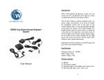
Download a-Sphere-HydroBatt Package Manual
Transcript
a-Sphere
Autonomous Deployment
Package
USER’S MANUAL
Hydro-Optics, Biology & Instrumentation
Laboratories
Lighting the Way in Aquatic Science
www.hobilabs.com
[email protected]
-2-
1. INTRODUCTION
This manual describes an autonomous deployment package that supplements an a-Sphere
in-situ spectrophotometer with two HydroBatt battery packs and a Seabird SBE-5 Pump.
Detailed information about each of these system components can be found in its
respective user’s manual, while this document addresses topics specific to the package
and its deployment.
The package is designed to
allow deployment of the a-Sphere
without an electrical connection to
the surface.
The HydroBatts
provide power, and the a-Sphere
logs data internally to its
nonvolatile flash memory. The aSphere also provides switched
power to the pump, which flows
water through the a-Sphere’s
sampling cavity.
The frame can be lowered
on any suitably strong winch cable.
The a-Sphere is positioned
in the frame such that its removable
hemisphere is easily accessible for
cleaning, either from the side of the
frame, or from the end if the frame
is tipped on its side.
-3-
2. PRECAUTIONS AND MAINTENANCE
In addition to those mentioned in the individual instrument manuals, observe the
following important precautions when using the system:
•
Be sure all instrument retaining clamps are firmly tightened.
•
Always secure the a-Sphere with an additional safety line from its mounting eye
to the frame.
•
Be sure the device housings are protected from direct contact with the metal
clamps and other metal parts.
•
Do not run the pump dry. Use the a-Sphere switch to turn it off when the package
is out of the water, or if necessary unplug it.
•
When connecting the battery packs to their Y-cable, plug one in immediately after
the other. Once the first pack is plugged in, its voltage appears on the second
connector, making it vulnerable to short circuits until that connector is plugged in.
This connector is “live” with the voltage from the first battery pack. Plug it
into the second pack immediately to reduce the risk of short circuits.
-4-
3. DEPLOYMENT CONSIDERATIONS
3.1.
Plumbing and Water Flow
The frame is configured to allow very simple plumbing
for the best possible water flow through the sphere.
The sphere outlet should be connected to the pump inlet
with a very short piece of tubing as shown at right.
The inlet on the removable hemisphere should
be equipped with a wire mesh strainer, also shown, to
keep objects and debris from entering the sphere.
3.2.
Power Conservation
The a-Sphere includes sophisticated thermal control
circuitry to stabilize both the light source and spectral
detector, and this control can consume a substantial
amount of power. The actual power consumption of
the a-Sphere may vary from about 7.5 to 30 W (35 W
peak) depending on ambient temperature. The highest
power is required during initial warmup, and the
steady-state consumption is highest when the ambient
temperature is low. The lowest power is required when the ambient temperature is about
20 C.
The pump requires an additional 6 to 8 W. Its consumption is directly related to
flow rate, and is highest when the plumbing is kept short and direct, as we recommend, to
maximize the flow.
With both HydroBatts fully charged, the system will provide at least 12 hours of
continuous operation, and often much longer. To maximize endurance we recommend
that whenever you operate the system on deck (for example when waiting for the thermal
stabilization before a cast or between casts) you connect it to an external power supply of
18 to 24 V, which will remove the load from the batteries. You can supply this external
power through the PDI cable.
To observe the voltage of the batteries, connect to the a-Sphere with a-Sphere
Console, open the terminal window, and type VIN. This will display the actual voltage
reaching the a-Sphere. It can operate with minimum input of 10 V. Keep in mind that
the voltage will be somewhat higher when the pump is not running.
-5-
3.3.
Pump Control
The pump is lubricated by water, so it should not be run dry. It is acceptable to run it for
short periods out of the water as long as its impeller mechanism is wet, for example at the
end of a cast when the package is being handled on deck. Similarly it can be run briefly
before the beginning of a cast, provided it is thoroughly wet. If necessary, you can
simply squirt water into the pump through its outlet before starting it.
The a-Sphere (Series 200 and later) is equipped with a switch to start and stop
logging, and this also controls the pump. However there may be circumstances, such as
testing, in which it is necessary to use the switch on deck. In those cases, one can simply
unplug the pump. If you do unplug the pump, be sure to include checking that
connection as part of your pre-deployment routine, because immersing the system with
the a-Sphere’s pump port unplugged could severely damage it.
3.4.
Recommended Deployment Sequence
1. Connect an 18 to 24 V power supply to the a-Sphere through its power/data
interface (PDI) cable. If the power supply voltage is lower than 16 V, leave the
batteries disconnected from the a-Sphere.
2. Connect the PDI to a computer.
3. Turn on the power and monitor the thermal stabilization with the a-Sphere
Console application.
4. (If necessary, squirt water into the pump to prepare it for use)
5. When the a-Sphere is stabilized and you are ready to deploy, connect the batteries
to the a-Sphere (if necessary), turn off the external power supply, then start
logging with the switch on the a-Sphere.
6. At the conclusion of the cast, turn off the switch on the a-Sphere as soon as it is
accessible.
7. If you wish to keep the thermal regulation active until the next cast, or if you wish
to offload data from the a-Sphere, connect the external power supply, turn it on,
then disconnect the batteries.
-6-
4. MECHANICAL PARTS AND TOOLS
The individual devices rest on plastic saddles that match their diameters, and are held in
place by hose clamps. Since direct contact with the metal hose clamps would damage the
device cases, the bands of the hose clamps are covered with PVC tubing. Eventually the
tubing and clamps may become worn and require replacement, so we list suitable parts
below. The part numbers are for McMaster-Carr Supply Company, www.mcmaster.com,
although equivalents are available from many other suppliers.
4.1.
Replaceable Parts
The hose clamps are constructed entirely of 316 stainless steel and have 5/8” bands and
vibration-resistant tightening mechanisms.
•
HydroBatt clamps: 4-3/4” to 5-5/8” diameter range, McMaster 5682K19
•
a-Sphere clamps: 7-1/4” to 8-1/8” diameter range, McMaster 5682K25
•
Pump clamp: 2” to 4-1/8” diameter range, McMaster 5682K52
•
Tubing: ½” internal diameter, 1/16” wall flexible PVC, McMaster 5231K88
The machined plastic saddles are held to the frame with ¼-20 x ¾” flat head 316 stainless
steel screws. The pump is also protected against direct clamping pressure by a rigid
stainless steel clamp with a plastic insert, McMaster 11355T73. These parts should not
normally need to be replaced.
4.2.
•
Tools
The hose clamps are tightened with a 5/16” socket or nut driver, or a flat-head
screwdriver.
-7-


