1
ASAHI AV VALVES
Installation Operation and Maintenance Manual
Serial No.
H-V036E-4
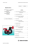
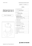
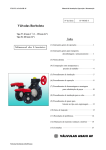
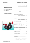
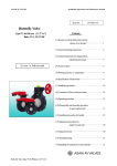
Butterfly Valves
Type 57 : 40mm(1 1/2”) - 350mm(14”)
Type 56 : 400mm(16”)
Contents
(1) General Operating Instructions
1
User’s Manual
(2) General Instructions for Transportation,
Unpacking and Storage
(3) Names of Parts
1
2
(4) Comparison between Working
Temperature and Pressure
4
(5) Installation Procedure
5
(6) Operating Procedure
8
(7) Disassembly and Assembly Procedure
for Parts Replacement
(8) Installation Procedure for Handle
10
12
(9) Adjustment Procedure for
Stopper on Gear Type
13
(10) Inspection Items
13
(11) Troubleshooting
14
(12) Handling of Residual and Waste Materials
14
(13) Inquires
15
ASAHI AV VALVES
Butterfly Valves (40-400mm)
0
ASAHI AV VALVES
Installation Operation and Maintenance Manual
(1) General Operating Instructions
○ Operate the valve within the pressure Vs temperature range.
(The valve can be damaged by operating beyond the allowable range.)
○ Select a valve material that is compatible with the media, refer to “CHEMICAL RESISTANCE ON ASAHI AV
VALVE”.
(Some chemicals may damage incompatible valve materials.)
○ Do not use the valve on condition that fluid has crystallized.
(The valve will not operate properly.)
○ Do not step on the valve or apply excessive weight on valve. (It can be damaged.)
○ Do not exert excessive force in closing the valve.
○ Make sure to consult a waste treatment dealer to dispose of the valves.
(Poisonous gas is generated when the valve is burned improperly.)
○ Allow sufficient space for maintenance and inspection.
○ Keep the valve away from excessive heat or fire. (It can be deformed, or destroyed.)
○ Do not change or replace valve parts under line pressure.
○ The valve is not designed to bear any kind of external load. Never stand on or place anything heavy on the valve at
anytime.
○ Using a positive-pressure gas with our plastic piping may pose dangerous condition due to the repellent force
peculiar to compressed fluids, even when the gas is under the same pressure as water. Therefore, be sure to take the
necessary safety precautions such as covering the piping protective material. For inquiries, please contact us.
(2) General Instructions for Transportation, Unpacking and Storage
○ Keep the valve in its original packaging until needed for installation.
○ Avoid contact with any coal tar creosote, insecticides, vermicides or paint.
(The force of swelling may damage the valve.)
○ The valve is not designed to handle any kind of impact. Avoid throwing or dropping the valve.
○ Avoid scratching the valve with any sharp object.
Butterfly Valves (40-400mm)
1
ASAHI AV VALVES
Installation Operation and Maintenance Manual
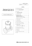
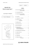
(3) Names of Parts
Type57: 40mm (1-1/2”) – 350mm (14”)
No.
Description
No.
Description
No.
Description
[1]
Body
[17]
Handle Lever
[24]
Cap (A)
[2]
Disc
[18]
Pin
[25]
Gear Box
[3]
Seat
[19]
Spring
[28]
Bolt (C)
[6]
O-Ring (C)
[20]
Washer (A)
[156]
[7]
Stem
[21]
Bolt (A)
[157]
Screw (F)
[8]
Stem Holder (A)
[22]
Locking Plate
[158]
Gasket (L)
[16]
Handle (A)
[23]
Screw (B)
Butterfly Valves (40-400mm)
Stabilization Ring
2
ASAHI AV VALVES
Installation Operation and Maintenance Manual
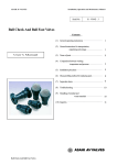
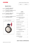
Type56 (Gear Type): 400mm (16”)
No.
Description
No.
Description
No.
Description
[1]
Body
[5]
O-Ring (B)
[28]
Bolt (C)
[2]
Disc
[6]
O-Ring (C)
[158]
Gasket (L)
[3]
Seat
[7]
Stem
[4]
O-Ring (A)
[25]
Gear Box
Butterfly Valves (40-400mm)
3
ASAHI AV VALVES
Installation Operation and Maintenance Manual
(4) Comparison between Working Temperature and Pressure
Caution
Do not operate the valve beyond the range of working temperature and pressure.
(The valve can be damaged.)
Butterfly Valves (40-400mm)
4
ASAHI AV VALVES
Installation Operation and Maintenance Manual
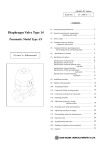
(5) Installation Procedure
Caution
1)
The valve disc is sent in the position indicated by. solid lines in Fig. 5-1 prior to shipment from the factory. If
the valve is opened or closed after unpacking, it must be reset in this position before installation. Failure to
do so will result in damage to the surface of the valve seat during handling and installation.
2)
The valve most not be dropped or thrown against other objects, since the sealing surface of the disc and the
sealing surface of the valve seat may easily be damaged.
3)
Care must be used during piping installation to ensure that the pipes or flanges are properly aligned so that
the valve disc does not contact them in any setting. Misalignment as in Fig.5-2 will result in damage to the
valve.
4)
The installed valve must never be opened or closed when foreign matter such as sand is present in the
pipeline.
Fig. 5-1
Fig. 5-2
NOT RECOMMENDED
INTERFERENCE OF THE DISK
RECOMMENDED
In case of the thick wall of the connection part (flange and pipe) is too thick, shave the flange or the pipe inside in order to avoid the
contact of pipe and disc. If inside diameter of the connection part is larger than size D, shaving is not necessity.
Nominal Size
40mm (1 1/2”)
50mm (2”)
65mm (2 1/2”)
80mm (3”)
100mm (4”)
125mm (5”)
150mm (6”)
200mm (8”)
250mm (10”)
300mm (12”)
350mm (14”)
400mm (16”)
Butterfly Valves (40-400mm)
Diameter D
30mm (1.18”)
44mm (1.73”)
67mm (2.64”)
71mm (2.80”)
90mm (3.54”)
115mm (4.53”)
136mm (5.35”)
179mm (7.05”)
237mm (9.33”)
289mm (11.38”)
340mm (13.39”)
370mm (14.57”)
5
ASAHI AV VALVES
Installation Operation and Maintenance Manual
Necessary items
● Torque Wrench
● Spanner Wrench
Procedure
Caution
The disk [2] is prevented from overflowing. (The disk [2] is damaged.)
1) Install the valve between flanges and open the valve slightly.
2) Insert bolts, set nuts and washer and tighten the bolts and nuts temporarily by
hand.
Caution
When you insert a valve between flanges, please
insert after extending the fields of flanges fully.
(If you insert a valve by force without fully
extending fields of flanges, a liner may be turned
over and suffer a crack.. )
The parallelism and axial misalignment of the flange surface should be under the values shown in the following table
to prevent damage the valve. (A failure to observe them can cause destruction due to stress application to the pipe)
Unit : mm (inch)
Nom. Size
40 - 80mm
(1 1/2”-3”)
100-150mm
(4”-6”)
200-400mm
(8”-16”)
Axial Misalignment
Parallelism (a – b)
1.0
(0.04)
1.0
(0.04)
1.5
(0.06)
0.8
(0.03)
1.0
(0.04)
1.0
(0.04)
(Axial Misalignment)
(Parallelism)
3) Tighten the bolts and nuts gradually with torque wrench to the specified torque in a diagonal manner.
(Refer to Fig. 5-3)
Recommended torque value
40mm
Nom. Size
(1 1/2”)
20.0
Torque value
{204}
[177]
Unit: N-m {kgf-cm} [lb-inch]
50, 65mm
80, 100 mm
(2”,2 1/2”)
(3”,4”)
22.5
30.0
{230}
{306}
[200]
[266]
125, 150 mm
200, 250 mm
300, 350 mm
(5”,6”)
(8”,10”)
(12”,14”)
40.0
55.0
60.0
Torque value
{408}
{561}
{612}
[355]
[488]
[532]
Caution : Avoid excessive tightening. (The valve can be damaged.)
Nom. Size
Butterfly Valves (40-400mm)
Fig. 5-3
400 mm
(16”)
80.0
{816}
[710]
6
ASAHI AV VALVES
Installation Operation and Maintenance Manual
<JIS Standard>
Dimension of Insert Bolt A
Nom. Size
40mm
50mm
65mm
80mm
100mm
125mm
150mm
200mm
250mm
300mm
350mm
1 1/2”
2”
2 1/2”
3”
4”
5”
6”
8”
10”
12”
14”
400mm
16”
Bolt (Minimum)
L
125mm (4.92”)
125mm (4.92”)
130mm (5.12”)
130mm (5.12”)
145mm (5.71”)
165mm (6.50”)
175mm (6.89”)
190mm (7.48”)
220mm (8.66”)
245mm (9.65”)
250mm (9.82”)
d
M16
M20
M22
M24
300mm (11.81”)
S
35mm
(1.38”)
Nut
Washer
M16
16mm
(0.63”)
M20
20mm
(0.79”)
M22
22mm
(0.87”)
M24
24mm
(0.94”)
40mm
(1.57”)
45mm
(1.77”)
Dimension of Insert Bolt B
Nom. Size
400mm
16”
d1
M24
Bolt (Minimum)
S1
L1
120mm
45mm
(4.72”)
(1.77”)
S2
27mm
(1.06”)
Nut
Washer
M24
24mm
(0.94”)
<ANSI Standard>
Dimension of Insert Bolt A
Nom. Size
40mm
50mm
65mm
80mm
100mm
125mm
150mm
200mm
250mm
300mm
350mm
1 1/2”
2”
2 1/2”
3”
4”
5”
6”
8”
10”
12”
14”
400mm
16”
Bolt (Minimum)
L
125mm (4.92”)
125mm (4.92”)
130mm (5.12”)
130mm (5.12”)
145mm (5.71”)
165mm (6.50”)
175mm (6.89”)
190mm (7.48”)
220mm (8.66”)
245mm (9.65”)
250mm (9.82”)
d
5/8”-11
3/4" - 10
7/8” - 9
1” - 8
300mm (11.81”)
S
35mm
(1.38”)
Nut
Washer
5/8” - 11
5/8” Flat
(0.63”)
3/4" - 10
3/4" Flat
(0.79”)
7/8” - 9
7/8” Flat
(0.87”)
1” - 8
1” Flat
(0.94”)
40mm
(1.57”)
45mm
(1.77”)
Dimension of Insert Bolt B
Nom. Size
400mm
16”
Bolt A
d1
1” - 8
Bolt (Minimum)
S1
L1
120mm
45mm
(4.72”)
(1.77”)
S2
27mm
(1.06”)
Nut
Washer
1” - 8
1” Flat
(0.94”)
Bolt B
Caution
The gasket is unnecessary. (The seat [3] carries out the role of the gasket.)
Butterfly Valves (40-400mm)
7
ASAHI AV VALVES
Installation Operation and Maintenance Manual
(6) Operating Procedure
Caution
The lever operation and the steering wheel operation are done by the hand.
1) Open and close the valve by turning handle smoothly.
(Turn clockwise to close and counterclockwise to open.)
2) In case of lever type (40-200 mm{1 1/2”-8”}), the direction of handle is same as the disc as shown in Fig. 6-1.
・ For the full-shut (Close) position, the handle is perpendicular to the piping axis direction.
・ For the full-opened position, the handle is parallel to the piping axis direction.
Full-Shut (Close) Position
Full- Opened Position
Fig. 6 – 1
3) In case of gear type (40-400 mm {1 1/2”-16”}), the indicator shows the position of the disc on the top of gear box.
(Fig.6-2)
・ For the full-shut (close) position, the indication shows Shut (S).
・ For the full-opened position, the indication shows Open (O).
Full-Shut (Close) Position
Full- Opened Position
Fig. 6 – 2
Butterfly Valves (40-400mm)
8
ASAHI AV VALVES
Installation Operation and Maintenance Manual
Technical Data for Operation
Nom.
Size
40mm
(1 1/2”)
50mm
(2”)
65mm
(2 1/2”)
80mm
(3”)
100mm
(4”)
125mm
(5”)
150mm
(6”)
200mm
(8”)
250mm
(10”)
300mm
(12”)
350mm
(14”)
400mm
(16”)
Stem Torque
(N・m)
Required Hand-Wheel
Torque
(N・m)
Length of Lever and
Diameter of Handle
(mm)
Required Operating Force
(N)
Peak
Seal
Peak
Seal
Lever
Gear
Lever
Gear
5
5
0.4
0.4
220
80
23
5.0
10
10
0.8
0.8
220
80
46
10
15
15
1.2
1.2
220
80
68
15
20
20
1.7
1.7
250
80
80
22
30
30
2.5
2.5
250
80
120
32
65
40
5.4
3.3
320
80
125
42
85
65
7.0
5.4
320
80
205
68
190
165
16
13
420
80
395
163
300
250
25
21
-
80
-
263
370
330
25
22
-
150
-
147
420
400
28
27
-
150
-
180
930
780
63
53
-
150
-
353
Note : Data mentioned in the table above is reference only.
These data are measured in standard condition and it slightly differs depending on conditions.
Butterfly Valves (40-400mm)
9
ASAHI AV VALVES
Installation Operation and Maintenance Manual
(7) Disassembly and Assembly Procedure for Parts Replacement
Necessary items
● Protective Gloves
● Vise
● Circular Stick (Plastic or Wood)
● Goggles
● Grease (Silicone)
● Pressing Machine
● Screw Driver (+)
● Spanner Wrench
● Square Lumber
● Hammer
● Screw Driver (–)
Caution
Wear protective gloves and goggles in case some dangerous fluid remains in the valve body.
(You might be injured by working without them.)
The handle part can be removed with line pressure present. The locking plate [22] can’t be removed with line pressure
present. If locking plate [22] needs to be removed, there can not be line pressure present.
<< Disassembly >>
Stabilization Ring [157]
Procedure
Seat [3]
1) Drain fluid completely from the pipeline.
2) Leave the valve slightly opened.
3) Loosen the connecting bolts and nuts.
4) Remove the valve from the pipeline.
Lever Type <Nominal size 40mm-200mm (1 1/2”-8”)
5) To remove handle[16], first take off the cap [24] by using
screw driver (–) and release bolt [21] by using socket wrench,
Body [1]
then pull up the handle [16] while holding handle lever[17].
6) To take off locking plate [22], release 4 self-tapping screws [23] by using screw driver(+) and take off stem
holder[8].
Gear Type <Nominal size 40mm-400mm (1 1/2”-16”)
5) Loosen set bolt [28] for gear box [25] and pull off the gear box upward with gasket [158].
6) <Nominal size 40mm-350mm (1 1/2”-14”) *It advances 400mm (16”) as follows.>
To take off stem holder [8]. Release 4 tapping screws [157] by using screw driver (+).
Lever & Gear Type
7) Hold flat surface of Stem [7] with vise and pull off valve body[1].
8) (A) Set the valve body [1] on square lumbers at edges of valve body on the press and put a lumber on the disc[2].
Operate the press slowly and push disc [2] and seat [3] out if the valve body[1].
(B) Set the valve body [1] on square lumbers at edges of valve body and put a circular stick on the disc[2].
Strike the circular stick with a hammer and remove disc [2] and seat [3] out of the valve body[1].
9) Set the disc [2] parallel to the working desk to half opened position. Push the seat[3], and remove the disc[2].
10) <Nominal size 40mm-350mm (1 1/2”-14”) *It advances 400mm (16”) as follows.>
Remove the stabilization ring [156] and the O-ring(C) [6]from the stem[7].
Butterfly Valves (40-400mm)
10
ASAHI AV VALVES
Installation Operation and Maintenance Manual
<< Assembly >>
Procedure
1) Put the O-ring(C) [6]onto the stem[7].
2) Before starting assembly, grease (Silicone) should be spread on the top and bottom disc[2], the stem hole of the
seat [3] and the stem O-ring(C)[6].
3) <Nominal size: 40mm-350mm(1 1/2”-14”) *It advances 400mm (16”) as follows.>
Insert the stabilization ring [156] into the upper side slot of the seat [3]. The upper side slot of seat [3] has larger
stem hole than lower side.
Caution
Make certain tabs are properly aligned. Both upper and lower stabilization ring [156] are identical.
4) Insert the stem [7] about 1/3 into the body [1]. Install the seat [3] into the body [1] by aligning upper seat stem hole
with the stem [7].
5) Collapse the left or right side of seat [3] in towards opposing side exposing lower stem hole by screw driver (–).
<Nominal size: 40mm-350mm (1 1/2”-14”) *It advances 400mm (16”) as follows.>
Install the stabilization ring [156] into the body [1] aligning tabs of ring with center groove of the body [1]. Seat [3]
tabs should line up when bottom of seat is reset into body of valve.
6) Remove the stem [7].
7) Reset the seat [3] into the body [1].
Caution
<Nominal size: 40mm-350mm(1 1/2”-14”) *It advances 400mm (16”) as follows.>
Make certain stabilization rings [156] sit flush inside of seat [3] with tabs properly aligned. If stabilization rings [156]
are not installed correctly, the seat [3] will not sit in the body [1] properly. This is indicated by a visible gap between seat
[1] and body [1], and disc [2] will not fit properly.
8) To install disc [2], make certain valve size on disc [2] is in upright direction. Install top of disc [2] into seat [3] aligning
with upper stem hole.
9) Rotate disc [2] to 75% (Approx.) closed position and install stem [7] about 50% into the body [1].
10) Press in bottom of disc [2] to lower stem hole.
Caution
Look into valve body [1] to be certain full square in disc [2] is centered with upper valve [1] stem hole. If not, repeat step 8),
9), and 10).
Make certain line scribed on top of stem [7] indicates disc [2] position while installing stem [7].
11) Install the stem [7] into valve body [1] and disc [2]. If disc [2] is properly aligned, stem [7] should slide in smoothly. If
stem [7] does not slide in smoothly, report from step 8) to properly align the disc [2] in the valve body [1].
12) <Nominal size: 40mm-350mm(1 1/2”-14”) *It advances 400mm (16”) as follows.>
Install stem holder [8] onto valve body [1] with countersunk holes facing up using 4 screws [157].
13) To install lever or gear operator reverse disassembly procedure #5).
14) After assembly, make sure that the valve can be fully opened and closed smoothly.
Butterfly Valves (40-400mm)
11
ASAHI AV VALVES
Installation Operation and Maintenance Manual
(8) Installation procedure for handle
Necessary items
●Plastic Hammer
●Socket Wrench
●Goggles
●Protective Gloves
●Screw Driver(–)
Caution
Do not give any unjust force to cap, in installing or removing the cap.
(It can be damaged)
《Installation》
Procedure
1)
Install the handle on the stem. Set the direction of handle in the
indication line at the top of stem.
2)
Fix the handle at the top of stem with the attached bolts and washer
by using socket wrench.
3)
Set the convex part at the side of the cap and the concave of the
handle, and set in the cap by striking lightly by using a plastic
hammer.
Nominal Size
Bolt Size
Socket Size
40-100mm
(1 1/2”-4”)
M6×15L
10
125-200mm
(5”-8”)
M8×15L
13
《Remove》
Procedure
1)
To remove the cap, push up the side of the cap by using screw driver
(–).
2)
Loose the bolts and washer by using socket wrench, then remove the
handle.
Butterfly Valves (40-400mm)
12
ASAHI AV VALVES
Installation Operation and Maintenance Manual
(9) Adjustment Procedure for Stopper Gear Type
Necessary Items
● Hexagon Wrench
The adjustments for full-opened and full-shut position are step-less, and it can be done with the stopper
adjuster.
Adjustment for Full-shut (Full-opened) position
Rubber Cap
1) Remove the rubber cap of Full-closing (Full-opening)
adjuster.
2) Loosen the first stopper hex-bolt completely by Hex.
Wrench.
3) Adjust the disc of valve to required position.
4) Tighten the stopper hex-bolts.
5) Put the rubber cap of Full-closing (Full-opening)
Adjuster for Full-Shut Position
adjuster back on gearbox.
Adjuster for Full-Opened Position
(10) Inspection Items
Inspect the following items.
(1)
Check for flaw, crack, or deformation on the valve.
(2)
Check for leaks to the outside.
(3)
Check for the deformation of seat due to improper installation of valve.
(4)
Check for the smoothness of handle operation..
Butterfly Valves (40-400mm)
13
ASAHI AV VALVES
Installation Operation and Maintenance Manual
(11) Troubleshooting
Phenomenon
Cause
Treatment
1) The stopper is not set correctly.
Adjust the stopper.
2) The seat is damaged or worn.
Replace the seat.
Fluid is not stopped in the full 3) Foreign materials are caught.
closed position at the seat.
4) The disc is damaged or worn.
Clean it up.
Replace the disc.
5) The connecting bolts are over tightened or Adjust and retighten.
tightened unevenly.
Replace the seat.
1) The seat is damaged or worn.
Fluid leaks to the outside.
2) The connecting bolts are not tightened in
proper torque or evenly.
1) Foreign materials have adhered.
The handle
smoothly.
does
not
work
2) The gear box is damaged.
3) The connecting bolt is over tightened.
Adjust and retighten.
Clean it up.
Repair or replace.
Adjust and retighten.
1) The gear box is damaged
Repair or replace.
2) The stem is damaged.
Replace the stem.
Valve does not operate
(12) Handling of Residual and Waste Materials
Caution
Make sure to consult waste treatment dealer to dispose valves.
(Poisonous gas is generated when the valve is burned improperly.)
Butterfly Valves (40-400mm)
14
ASAHI AV VALVES
Installation Operation and Maintenance Manual
(13) Inquiries
ASAHI ORGANIC CHEMICALS INDUSTRY CO., LTD.
Nobeoka Head Office
: 2-5955, Nakanose- Cho, Nobeoka –City, Miyazaki- Pref. , Japan.
Tel : (81) 982-35-0880
Tokyo Head Office
Fax : (81) 982-35-9350
: (Furukawachiyoda Bldg.) 15-9, Uchikanda 2- Chome, Chiyoda-Ku, Tokyo, Japan.
Tel : (81) 3-3254-8177
Singapore Branch Office
Fax : (81) 3-3254-3474
: 16 Raffles Quay, #40-03 Hong Leong Building, Singapore 048581.
Tel : (65) 220-4022
Fax : (65) 324-6151
Europe Representative Office : Kaiser-Friedrich-Promenade 61 D-61348 Bad Homburg v. d. H. Germany.
Tel : (49) 6172-9175-0
Shanghai Branch Office
: Room 1301-P Shanghai Kerry Center, 1515 Nanjing Xi Road, Shanghai China
Tel : (21) 5298-6900
ASAHI /AMERICA Inc.
Fax : (49) 6172-9175-25
Fax : (21) 5298-6556
:35 Green Street P.O.Box 653 , Malden, Massachusetts 02148 U.S.A.
Tel : (1) 781-321-5409
Fax : (1) 781-321-4421
Distributor
Butterfly Valves (40-400mm)
15
ASAHI AV VALVES
Installation Operation and Maintenance Manual
Butterfly Valves
40mm-350mm(1 1/2”-14”) Type 57
400mm(16”) : Type 56
ASAHI AV VALVES
Information in this manual is subject to change without notice.
Butterfly Valves (40-400mm)
2006. 2
16