1
ASAHI AV VALVES
Installation,Operation and Maintenance Manual
Serial No.
H-V028 E-8-CE
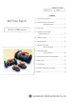
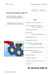
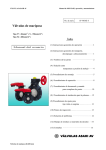
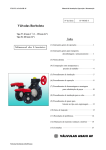
Diaphragm Valves Type 14
True Union Diaphragm Valves Type14
User ’s Manual
Contents
(1) General operating instructions
1
(2) General instructions for transportation,
unpacking and storage
1
(3) Name of parts
2
(4) Comparison between working
temperature and pressure
4
(5) Installation procedure
5
(6) Operating procedure
9
(7) Adjustment procedure for stopper
9
(8) Diaphragm replacement procedure
12
(9)
13
Mounting an inserted and a base (panel)
(10) Inspection items
13
(11) Troubleshooting
14
(12) Handling of residual and
waste materials
14
(13) Marking
15
(14) Inquiries
16
ASAHI AV VALVES
Diaphragm Valves Type 14 True Union Diaphragm Valves Type14-CE
0
ASAHI AV VALVES
Installation,Operation and Maintenance Manual
(1) General operating instructions
○ Operate the valve within the pressure Vs temperature range.
(The valve can be damaged by operating beyond the allowable range.)
○ Select a valve material that is compatible with the media, refer to “CHEMICAL RESISTANCE ON ASAHI AV
VALVE”.
(Some chemicals may damage incompatible valve materials.)
○ Bonnet bolt torque should be checked before installation, as they may become loose after long-term storage. A
periodic check of the valve condition as well as bonnet & flange bolt torque should be made part of preventative
maintenance program properly re-tightening the bolts as necessary. It is especially important to re-tighten all
bolts during the first shutdown.
(Refer to page 5.)
○ The travel stop may have to be adjusted if media leakage is detected between the upstream & downstream sides
of the valve.
○ Do not step on the valve or apply excessive weight on valve. (It can be damaged.)
○ Do not exert excessive force in closing or opening the valve.
○ Make sure to consult a waste treatment dealer to dispose of the valves.
(Poisonous gas is generated when the valve is burned improperly.)
○ Allow sufficient space for maintenance and inspection.
○ Keep the valve away from excessive heat or fire. (It can be deformed, or destroyed.)
○ The valve should be operated by hand.
(2) General instructions for transportation, unpacking and strange
○ Keep the valve packed in the carton or box as delivered until installation.
○ Keep the valve away from coal tar, creosote (antiseptic for wood ), termite insecticide, vermicides, and paint.
(The could cause swelling and damage the valve.)
○ Do not impact or drop the valve. (It can be damaged.)
○ Avoid scratching the valve with any sharp object.
Diaphragm Valves Type 14 True Union Diaphragm Valves Type14-CE
1
ASAHI AV VALVES
Installation,Operation and Maintenance Manual
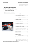
(3) Name of parts
4 is available only when diaphragm ◯
3a is PTFE .
Diaphragm ◯
No.
1
◯
2
◯
3b
◯
3a
◯
4
◯
6
◯
7
◯
8
◯
9
◯
10
◯
DESCRIPTION
Body
Bonnet
Diaphragm
Inserted metal of DIA
Cushion
Compressor
Joint
Stem
Sleeve
Handle wheel
No.
11
◯
12
◯
13
◯
14
◯
15
◯
16
◯
17
◯
18
◯
18a
19
◯
DESCRIPTION
Gauge cover
Name Plate
Retaining ring c-type
O-ring (A)
O-ring (B)
Thrust ring (A)
Thrust ring (B)
Bolt, Nut (A)
Washer
Conical spring washer
Diaphragm Valves Type 14 True Union Diaphragm Valves Type14-CE
No.
20
◯
21
◯
24
◯
25b
25c
25e
26
◯
27
◯
DESCRIPTION
Stopper
Screw
Metal insert (Ensat)
End connector (Socket end)
End connector (Threaded end)
End connector(Spigot end)
Union nut
O-ring (C)
2
ASAHI AV VALVES
Installation,Operation and Maintenance Manual
4 is available only when diaphragm ◯
3a is PTFE .
Diaphragm ◯
No.
1
◯
2
◯
3
◯
3a
◯
4
◯
6
◯
7
◯
8
◯
DESCRIPTION
Body
Bonnet
Diaphragm
Inserted metal of DIA
Cushion
Compressor
Joint
Stem
No.
9
◯
10
◯
11
◯
12
◯
13
◯
14
◯
15
◯
16
◯
DESCRIPTION
Sleeve
Handwheel
Gauge cover
Name plate
Retaining ring-c type
O-ring(A)
O-ring(B)
Thrust ring(A)
Diaphragm Valves Type 14 True Union Diaphragm Valves Type14-CE
No.
17
◯
18
◯
18a
20
◯
89
◯
90
◯
98
◯
99
◯
DESCRIPTION
Thrust ring(B)
Bolt, Nut (A)
Washer (A)
Stopper
Compressor pin
Inserted nut
Spring washer
Valve sheet
3
ASAHI AV VALVES
Installation,Operation and Maintenance Manual
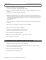
(4) Comparison between operating temperature and pressure
Flange
True Union(Socket, Threaded, Spigot)
Caution
Do not operate valve beyond the range of working temperature and pressure.
(The valve can be damaged.)
Diaphragm Valves Type 14 True Union Diaphragm Valves Type14-CE
4
ASAHI AV VALVES
Installation,Operation and Maintenance Manual
(5) Installation procedure
Flanged type (Material : PVC, C-PVC, PP, PVDF)
Necessary items
● Torque wrench
● Spanner wrench
● AV gasket (When a non-AV gasket is used ,a different tightening torque specification should be followed.)
● Bolt, Nut, Washer (For many flanges specification)
Procedure
1) Set the AV gasket between the flanges.
2) Insert washers and bolts from the pipe side, insert washers and nuts from the valve side, then temporarily
tighten them by hand.
Caution
The parallelism and axial misalignment of the flange surface should be under the values shown in the
following table to prevent damage the valve.
(A failure to observe them can cause destruction due to stress application to the pipe.)
Unit : mm (inch)
Nom. Size
15-32mm
(1/2”-1 1/4”)
40, 50mm
(1 1/2”-2”)
65-100mm
(2 1/2”-4”)
Axial
misalignment
Parallelism
(a-b)
1.0 (0.04)
0.5 (0.02)
1.0 (0.04)
0.8 (0.03)
1.0 (0.04)
(0.04)
(Axial misalignment)
(Parallelism)
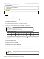
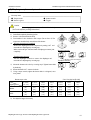
3) Tighten the bolts and nuts gradually with a torque wrench to the specified torque level in a diagonal manner.
(Refer to Fig.1.)
Recommended torque value
15-20mm
Nom. Size
(1/2”-3/4”)
17.5
Torque value
{179}
[155]
25-40mm
(1”-1 1/2”)
20.0
{204}
[177]
Unit: N-m {kgf-cm} [lb-inch]
50, 65mm
80, 100mm
(2”-2 1/2”)
(3”, 4”)
22.5
30.0
{230}
{306}
[200]
[266]
Fig. 1
Caution
Avoid excessive tightening. (The valve can be damaged.)
Diaphragm Valves Type 14 True Union Diaphragm Valves Type14-CE
5
ASAHI AV VALVES
Installation,Operation and Maintenance Manual
Threaded type (Material : PVC, C-PVC, PP, PVDF)
Necessary items
● Sealing tape(A non-sealing tape can cause leakage.)
● Strap wrench(Do not use Pipe wrench.)
● Spanner wrench
Caution
Make sure that the threaded connections are plastic x plastic.
(Metallic thread can destroy the body cap)
Procedure
1) Wind a sealing tape around the external thread of joint, leaving the end (about 3mm) free.
26 with a strap wrench..
2) Loosen the union nut ◯
26 and the end connector 25b .
3) Remove the union nut ◯
26 through the pipe.
4) Lead the union nut ◯
5) Tighten the external thread of the joint and the end connector 25b hardly with hand.
6) Using a spanner wrench, screw in the end connector 25b by turning 180°- 360°carefully without damaging it.
Caution
Avoid excessive tightening. (The valve can be damaged.)
27 is mounted.
7) Make sure that the O-ring (C) ◯
26 directly on the body without allowing the O-ring (C) ◯
27 to
8) Set the end connector 25b and union nut ◯
come off.
26 on each valve until hand tight.
9) Tighten union nut ◯
10) Using a strap wrench tighten union nuts uniformly on each side approx 90°- 180°turns, 1/4 to 1/2 turns.
Caution
Avoid excessive tightening. (The valve can be damaged.)
Diaphragm Valves Type 14 True Union Diaphragm Valves Type14-CE
6
ASAHI AV VALVES
Installation,Operation and Maintenance Manual
Socket type (Material : PVC,C-PVC)
Necessary items
● Adhesive for hard vinyl chloride pipes
● Strap wrench
Caution
Do not install a socket type valve where the atmospheric temperature is 5℃or lower.
(The valve can be damaged.)
Procedure
26 with a strap wrench.
1) Loosen the union nut ◯
26 and end connector 25b .
2) Remove the union nut ◯
3) Lead the union nut through the pipe.
4) Clean the hub part of the end connector 25b by wiping with a waste cloth.
5) Apply adhesive evenly to the hub part of the end connector 25b and the pipe spigot.
Caution
Do not apply more adhesives than necessary.
(The valve can be damaged due to solvent cracking.)
Adhesive quantity (guideline)
15mm 20mm
Nom. Size
(1/2”)
(3/4”)
Quantity(g)
1.0
1.3
25mm
(1”)
2.0
32mm 40mm
(1 1/4”) (1 1/2”)
2.4
3.5
50mm
(2”)
65mm
(2 1/2”)
80mm
(3”)
100mm
(4”)
4.8
6.9
9.0
13.0
6) After applying adhesive, insert the pipe quickly to the end connector 25b and leave it alone for at least 60
seconds.
7) Wipe away overflowing adhesive.
27 is mounted
8) Make sure that O-ring(C) ◯
26 on each valve until hand tight.
9) Tighten union nut ◯
10) Using a strap wrench tighten union nuts uniformly on each side approx. 90°- 180°turns, 1/4 to 1/2 turns.
11) Using a strap wrench, screw it in by turning 90°- 180°carefully without damaging it.
Caution
Avoid excessive tightening. (The valve can be damaged.)
Diaphragm Valves Type 14 True Union Diaphragm Valves Type14-CE
7
ASAHI AV VALVES
Installation,Operation and Maintenance Manual
Socket type (Material : PP,PVDF )
Spigot type (Material : PP,PVDF)
Necessary items
● Strap wrench (Do not use the pipe wrench.)
● Sleeve welder or automatic welding machine
● User’s manual for sleeve welder or automatic welding machine
Procedure
1) Loosen the union nut with a strap wrench.
26 and the end connector 25b .
2) Remove the union nut ◯
26 through the pipe.
3) Lead the union nut ◯
4) For the next step, refer to the user’s manual for the sleeve welder or the automatic welding machine.
27 is mounted.
5) After welding, make sure that the O-ring (C) ◯
26 directly without allowing the O-ring (C) ◯
27 to come off.
6) Set the end connector 25b and the union nut ◯
26 on each valve until hand tight.
7) Tighten union nut ◯
8) Using a strap wrench tighten union nuts uniformly on each side approx. 90°- 180°turns, 1/4 to 1/2 turns.
Caution
Avoid excessive tightening. (The valve can be damaged.)
Diaphragm Valves Type 14 True Union Diaphragm Valves Type14-CE
8
ASAHI AV VALVES
Installation,Operation and Maintenance Manual
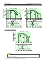
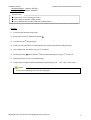
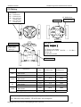
(6) Operating Procedure
○ Open and shut the valve by rotating handle wheel.
○ The top of the travel stop will be flush with the top of the handle wheel when the valve is fully closed.
< Nominal size : 15-50mm (1/2”-2”)>
Full open
Half open
Full shut
< Nominal size : 65-100mm (2 1/2”-4”)>
Full open
Half open
Full shut
Caution
The valve is designed for manual operation only.
(The use of assist device may damage the valve.)
(7) Adjustment procedure for stopper
Necessary items
● Spanner wrench
● Screw driver(-)
<15-50mm>
● Allen wrench
● Protective Gloves
● Goggles
<65-100mm>
Diaphragm Valves Type 14 True Union Diaphragm Valves Type14-CE
9
ASAHI AV VALVES
Installation,Operation and Maintenance Manual
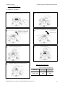
Travel stop adjustment
< Nominal size : 15-50mm >
①
Turn valve handle clockwise to the full closed position. Remove the
gauge cover, being careful not to damage the gauge cover O-ring.
⑤
Remove the travel stop / position indicator with a spanner wrench
②
and loosen the axial set screw counterclockwise with an Allen wrench.
⑥
Tighten the travel stop clockwise until it stop
and the turn it back (counter-clockwise)180°.
Secure the travel stop/position indicator with wrench and tighten the axial
set screw clockwise
The axial set screw is located within
with an Allen wrench.
the brass travel stop looking down..
③
④
Loosen the travel stop counter-clockwise.
⑦
Re-attach the gauge cover.
Slowly tighten the handwheel clock wise until the leak-by stops.
Tightening torque of the screw
Unit : N-m {kgf-cm} [lb-inch]
15-32mm
40, 50mm
Nom. Size
(1/2”-1 1/4”)
(1 1/2”, 2”)
8.0
12.0
Torque value
{81}
{122}
[71]
[106]
Diaphragm Valves Type 14 True Union Diaphragm Valves Type14-CE
10
ASAHI AV VALVES
Installation,Operation and Maintenance Manual
Travel stop adjustment
< Nominal size 65-100mm >
11 with hand.
1) Loosen the gauge cover ◯
20 from the lower nut ◯
20 with spanner wrench.
2) Loosen the upper nut ◯
20 .
3) Loosen the lower nut ◯
4) Operate the handle wheel to tighten gradually until the leakage of fluid stops.
20 until it stop, and then turn it back (counter-clockwise) 180°.
5) Tighten the lower nut ◯
20 to the lower nut ◯
20 with spanner wrench.
6) Tighten the upper nut ◯
11 .
7) Tighten the gauge cover ◯
Tightening torque of the screw
Nom. Size
Torque valve
Unit : N-m {kgf-cm} [lb-inch]
65-100mm
(2 1/2”-4”)
15.0 {153} [133]
Diaphragm Valves Type 14 True Union Diaphragm Valves Type14-CE
11
ASAHI AV VALVES
Installation,Operation and Maintenance Manual
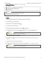
(8) Diaphragm replacement procedure
Necessary items
● Torque wrench
● Protective gloves
● Spanner wrench
● Goggles
Caution
Wear protective gloves and goggles because some fluid is left in the body.
(You can be injured by working without then.)
1) Drain fluid completely from the pipe line.
2) Remove valve bonnet from the body.
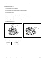
3) Turn handle of valve clockwise until it stops.(Do not force it).The
compressor should be fully extended out of the bonnet.
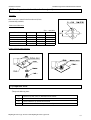
4) Bayonet connection type (standard)
Remove the diaphragm from the compressor by turning it 90°and
mount the new diaphragm by reversing step.
Make sure that the pin of inserted metal of diaphragm connects joint
completely.
Threaded connection type
Turn the diaphragm clockwise to remove the diaphragm and
mount the new diaphragm by reversing step.
Bayonet connection
Inserted metal of diaphragm
Threaded connection
Joint
5) Mount the bonnet to the valve by reversing step 2. Tighten bonnet bolts
by hand only.
6) Rotate the handle 360°counter-clockwise.
7) Using a torque wrench, tighten the bonnet bolts in a diagonal, crosscross pattern.
Bonnet torque value
Nom. Size
15, 20mm
(1/2”, 3/4”)
Diaphragm
Rubber
PTFE
3.0
{31}
[27]
5.0
{51}
[44]
Unit : N-m{kgf-cm}[ib-inch]
25, 32mm
(1”, 1 1/4”)
40mm
(1 1/2”)
50mm
(2”)
65mmm
(2 1/2”)
80mm
(3”)
100mm
(4”)
5 .0
{51}
[44]
8.0
{82}
[71]
12.0
{122}
[106]
15.0
{153}
[133]
15.0
{153}
[133]
20.0
{204}
[177]
13.0
{133}
[115]
15.0
{153}
[133]
18.0
{184}
[160]
20.0
{204}
[177]
35.0
{357}
310
40.0
{408}
[355]
8) Re-adjust the stopper if necessary.
Diaphragm Valves Type 14 True Union Diaphragm Valves Type14-CE
12
ASAHI AV VALVES
Installation,Operation and Maintenance Manual
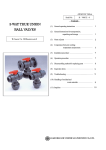
(9) Mounting an inserted metal, and a base (panel)
Procedure
Refer to the user’s manual for the Inserted metal (Ensat)
(Commercially available).
Bottom stand dimension
Unit ; mm (inch)
Nom. Size
S1
S2
S3
15-32mm (1/2”-1 1/4”)
40, 50mm (1 1/2”, 2”)
65mm (2 1/2”)
80mm (3”)
100mm (4”)
25 (0.98)
45 (1.77)
85 (3.35)
100 (3.94)
120 (4.72)
7 (0.28)
9 (0.35)
11 (0.43)
15 (0.59)
15 (0.59)
13 (0.51)
15 (0.59)
20 (0.79)
28 (1.10)
28 (1.10)
Fixation of bottom stand with panel
(10) Inspection items
○Inspect the following items.
(1)
Check for any flaw, crack, or deformation on the outside.
(2)
Check whether fluid leaks to the outside.
(3)
Check whether the cap nut has been loosened.
(4)
Check whether the handle can be operated smoothly.
Diaphragm Valves Type 14 True Union Diaphragm Valves Type14-CE
13
ASAHI AV VALVES
Installation,Operation and Maintenance Manual
(11) Troubleshooting
Problem
Cause
Treatment
The travel stop is not set correctly.
Adjust the travel stop.
Fluid is leaking past the fully closed Solid particles have lodged in the Clear the solid particles from the
position.
valve.
valve.
Media has worn diaphragm and / or
Replace.
weir.
Replace diaphragm. If the valve is in
The diaphragm has pulled off the vacuum service, special vacuum
stem.
valves may be required.
Consult factory.
Valve can not be fully open.
Remove
The metal joint failed.
Diaphragm & compressor and replace
joint.
Disassemble bonnet and replace the
The stem is broken.
stem.
The handle spins freely.
Remove diaphragm & compressor
The metal joint failed.
and replace joint.
Bonnet bolts have loosened.
Media has crystallized on
Valve leaks between body and bonnet.
diaphragm.
Re-tighten.
the
Disassemble and clean on a regular
basis. Replace failed diaphragm, if
necessary.
The diaphragm has failed due to
Replace.
fatigue.
Valve leaks from stem.
The diaphragm has failed.
Replace.
(12) Handling of residual and waste materials
Caution
In discarding remaining or waste materials, be sure to ask a waste service company.
(Poisonous gas is generated.)
Diaphragm Valves Type 14 True Union Diaphragm Valves Type14-CE
14
ASAHI AV VALVES
Installation,Operation and Maintenance Manual
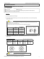
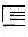
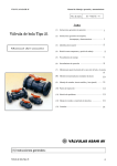
(13) Marking
EN marking
DN : Nominal size
PN : Nominal press.
TB : Max. allowable
working temp.
PB : Max. allowable
working press.
※ Molded date
Valve type
Date marking
Bottom view
Valve label
AOC symbol
02 B 00001 F
① ②
EN marking
・In case of true
union type
①
②
③
④
③
④
Year (ex. 02→2002)
Month (ex. A→Jan. B→Feb. …… L→Dec.)
Ser. No.
Revision symbol
CE0035 label
Material
PVC
C-PVC
PP
PVDF
Nominal size
DN15, DN20, DN25,DN32,
DN40, DN50
DN65, DN80, DN100
DN15, DN20, DN25,DN32,
DN40, DN50
DN65, DN80, DN100
DN15, DN20, DN25,DN32,
DN40, DN50
DN65, DN80, DN100
DN15, DN20, DN25,DN32,
DN40, DN50
DN65, DN80, DN100
Nominal
press.
Max. allowable
working temp.
Max. allowable
working press.
PN10
60℃
7 BAR
PN10
60℃
8 BAR
PN10
90℃
3 BAR
PN10
90℃
6 BAR
PN10
90℃
5 BAR
PN10
90℃
6 BAR
PN10
120℃
5 BAR
PN10
120℃
5 BAR
Note. Label of “CE0035” are applied to valves DN32 and over.
If the nameplate is damaged or become dirty, let our Sales Division know
the “Manufacturing number”. We will send a new nameplate.
Diaphragm Valves Type 14 True Union Diaphragm Valves Type14-CE
15
ASAHI AV VALVES
Installation,Operation and Maintenance Manual
(14) Inquiries
ASAHI ORGANIC CHEMICALS INDUSTRY CO., LTD.
Nobeoka Head Office
: 2-5955, Nakanose- Cho, Nobeoka –City, Miyazaki- Pref. , Japan.
Tel : (81) 982-35-0880 Fax : (81) 982-35-9350
Tokyo Head Office
: (Furukawachiyoda Bldg.) 15-9, Uchikanda 2- Chome, Chiyoda-Ku, Tokyo, Japan.
Tel : (81) 3-3254-8177 Fax : (81) 3-3254-3474
Singapore Branch Office
: 16 Raffles Quay, #40-03 Hong Leong Building, Singapore 048581.
Tel : (65) 220-4022 Fax : (65) 324-6151
Europe Representative Office : Kaiser-Friedrich-Promenade 61 D-61348 Bad Homburg v. d. H. Germany.
Tel : (49) 6172-9175-0 Fax : (49) 6172-9175-25
Shanghai Branch Office
ASAHI /AMERICA Inc.
: Room 1301-P Shanghai Kerry Center, 1515 Nanjing Xi Road, Shanghai China
Tel : (21) 5298-6900 Fax : (21) 5298-6556
:35 Green Street P.O.Box 653 , Malden, Massachusetts 02148 U.S.A.
Tel : (1) 781-321-5409 Fax : (1) 781-321-4421
Distributor
Diaphragm Valves Type 14 True Union Diaphragm Valves Type14-CE
16
ASAHI AV VALVES
Installation,Operation and Maintenance Manual
Diaphragm Valve Type 14
True Union Diaphragm Valve Type 14
ASAHI AV VALVES
Information in this manual is subject to change without notice.
Diaphragm Valves Type 14 True Union Diaphragm Valves Type14-CE
2003. 6
17