1
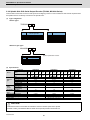
Introduction
Thank you for selecting the Mitsubishi numerical control unit. This instruction manual describes the handling and
caution points for using this AC servo/spindle. Incorrect handling may lead to unforeseen accidents, so always read
this instruction manual thoroughly to ensure correct usage.
In order to confirm if all function specifications described in this manual are applicable, refer to the specifications for
each CNC.
Notes on Reading This Manual
(1) Since the description of this specification manual deals with NC in general, for the specifications of individual
machine tools, refer to the manuals issued by the respective machine manufacturers. The "restrictions" and
"available functions" described in the manuals issued by the machine manufacturers have precedence to
those in this manual.
(2) This manual describes as many special operations as possible, but it should be kept in mind that items not
mentioned in this manual cannot be performed.
Precautions for Safety
Please read this manual and auxiliary documents before starting installation, operation, maintenance or inspection
to ensure correct usage. Thoroughly understand the device, safety information and precautions before starting
operation.
The safety precautions in this instruction manual are ranked as "WARNING" and "CAUTION".
DANGER
When there is a potential risk of fatal or serious injuries if handling is mistaken.
WARNING
When a dangerous situation, or fatal or serious injuries may occur if handling is mistaken.
CAUTION
When a dangerous situation may occur if handling is mistaken leading to medium or minor injuries, or physical damage.
Note that some items described as "
CAUTION" may lead to major results depending on the situation. In any
case, important information that must be observed is described.
The signs indicating prohibited and mandatory matters are explained below.
Indicates a prohibited matter. For example, "Fire Prohibited" is indicated as
Indicates a mandatory matter. For example, grounding is indicated as
.
.
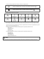
The meaning of each pictorial sign is as follows.
CAUTION
CAUTION rotated
object
CAUTION HOT
Danger Electric shock
risk
Danger explosive
Prohibited
Disassembly is
prohibited
KEEP FIRE AWAY
General instruction
Earth ground
After reading this specifications and instructions manual, store it where the user can access it easily for reference.
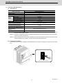
The numeric control unit is configured of the control unit, operation board, servo drive unit, spindle drive unit, power
supply, servo motor and spindle motor, etc.
In this section "Precautions for safety", the following items are generically called the "motor".
• Servo motor
• Linear servo motor
• Spindle motor
• Direct-drive motor
In this section "Precautions for safety", the following items are generically called the "unit".
• Servo drive unit
• Spindle drive unit
• Power supply unit
• Scale interface unit
• Magnetic pole detection unit
POINT
Important matters that should be understood for operation of this machine are indicated as a POINT in this manual.
WARNING
1. Electric shock prevention
Do not open the front cover while the power is ON or during operation. Failure to observe this could lead to
electric shocks.
Do not operate the unit with the front cover removed. The high voltage terminals and charged sections will
be exposed, and can cause electric shocks.
Do not remove the front cover and connector even when the power is OFF unless carrying out wiring work
or periodic inspections. The inside of the units is charged, and can cause electric shocks.
Since the high voltage is supplied to the main circuit connector while the power is ON or during operation,
do not touch the main circuit connector with an adjustment screwdriver or the pen tip. Failure to observe
this could lead to electric shocks.
Wait at least 15 minutes after turning the power OFF, confirm that the CHARGE lamp has gone out, and
check the voltage between P and N terminals with a tester, etc., before starting wiring, maintenance or
inspections. Failure to observe this could lead to electric shocks.
Ground the unit and motor. For the motor, ground it via the drive unit.
Wiring, maintenance and inspection work must be done by a qualified technician.
Wire the servo drive unit and servo motor after installation. Failure to observe this could lead to electric
shocks.
Do not touch the switches with wet hands. Failure to observe this could lead to electric shocks.
Do not damage, apply forcible stress, place heavy items on the cables or get them caught. Failure to
observe this could lead to electric shocks.
After assembling the built-in IPM spindle motor, if the rotor is rotated by hand etc., voltage occurs between
the terminals of lead. Take care not to get electric shocks.
WARNING
2. Injury prevention
When handling a motor, perform operations in safe clothing.
In the system where the optical communication with CNC is executed, do not see directly the light
generated from CN1A/CN1B connector of drive unit or the end of cable. When the light gets into eye, you
may feel something is wrong for eye.
(The light source of optical communication corresponds to class1 defined in JISC6802 or IEC60825-1.)
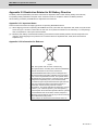
The linear servo motor, direct-drive motor and built-in IPM spindle motor uses permanent magnets in the
rotor, so observe the following precautions.
(1)Handling
• The linear servo motor, direct-drive motor and built-in IPM spindle motor could adversely affect medical
electronics such as pacemakers, etc., therefore, do not approach the rotor.
• Do not place magnetic materials as iron.
• When a magnetic material as iron is placed, take safety measure not to pinch fingers or hands due to the
magnetic attraction force.
• Remove metal items such as watch, piercing jewelry, necklace, etc.
• Do not place portable items that could malfunction or fail due to the influence of the magnetic force.
• When the rotor is not securely fixed to the machine or device, do not leave it unattended but store it in the
package properly.
• When installing the motor to the machine, take it out from the package one by one, and then install it.
• It is highly dangerous to lay out the motor or magnetic plates together on the table or pallet, therefore never
do so.
(2)Transportation and storage
• Correctly store the rotor in the package to transport and store.
• During transportation and storage, draw people's attention by applying a notice saying "Strong magnetHandle with care" to the package or storage shelf.
• Do not use a damaged package.
(3)Installation
• Take special care not to pinch fingers, etc., when installing (and unpacking) the linear servo motor.
CAUTION
1. Fire prevention
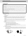
Install the units, motors and regenerative resistor on non-combustible material. Direct installation on
combustible material or near combustible materials could lead to fires.
Always install a circuit protector and contactor on the servo drive unit power input as explained in this
manual. Refer to this manual and select the correct circuit protector and contactor. An incorrect selection
could result in fire.
Shut off the power on the unit side if a fault occurs in the units. Fires could be caused if a large current
continues to flow.
When using a regenerative resistor, provide a sequence that shuts off the power with the regenerative
resistor's error signal. The regenerative resistor could abnormally overheat and cause a fire due to a fault
in the regenerative transistor, etc.
The battery unit could heat up, ignite or rupture if submerged in water, or if the poles are incorrectly wired.
Cut off the main circuit power with the contactor when an alarm or emergency stop occurs.
2. Injury prevention
Do not apply a voltage other than that specified in this manual, on each terminal. Failure to observe this
item could lead to ruptures or damage, etc.
Do not mistake the terminal connections. Failure to observe this item could lead to ruptures or damage,
etc.
Do not mistake the polarity (+,- ). Failure to observe this item could lead to ruptures or damage, etc.
Do not touch the radiation fin on unit back face, regenerative resistor or motor, etc., or place parts (cables,
etc.) while the power is turned ON or immediately after turning the power OFF. These parts may reach high
temperatures, and can cause burns or part damage.
Structure the cooling fan on the unit back face, etc., etc so that it cannot be touched after installation.
Touching the cooling fan during operation could lead to injuries.
Take care not to suck hair, clothes, etc. into the cooling fan.
CAUTION
3. Various precautions
Observe the following precautions. Incorrect handling of the unit could lead to faults, injuries and electric shocks, etc.
(1) Transportation and installation
Correctly transport the product according to its weight.
Use the motor's hanging bolts only when transporting the motor. Do not transport the machine when the
motor is installed on the machine.
Do not stack the products above the tolerable number.
Follow this manual and install the unit or motor in a place where the weight can be borne.
Do not get on top of or place heavy objects on the unit.
Do not hold the cables, axis or encoder when transporting the motor.
Do not hold the connected wires or cables when transporting the units.
Do not hold the front cover when transporting the unit. The unit could drop.
Always observe the installation directions of the units or motors.
Secure the specified distance between the units and control panel, or between the servo drive unit and
other devices.
Do not install or run a unit or motor that is damaged or missing parts.
Do not block the intake or exhaust ports of the motor provided with a cooling fan.
Do not let foreign objects enter the units or motors. In particular, if conductive objects such as screws or
metal chips, etc., or combustible materials such as oil enter, rupture or breakage could occur.
Provide adequate protection using a material such as connector for conduit to prevent screws, metallic
detritus, water and other conductive matter or oil and other combustible matter from entering the motor
through the power line lead-out port.
The units, motors and encoders are precision devices, so do not drop them or apply strong impacts to
them.
CAUTION
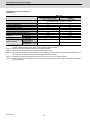
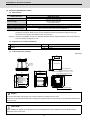
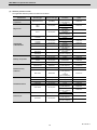
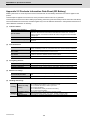
Store and use the units under the following environment conditions.
Environment
Ambient temperature
Ambient humidity
Atmosphere
Altitude
Unit
Operation: 0 to 55°C (with no freezing),
Storage / Transportation: -15°C to 70°C
(with no freezing)
Motor
Operation: 0 to 40°C (with no freezing),
Storage: -15°C to 70°C (Note2) (with no freezing)
Operation: 90%RH or less
(with no dew condensation)
Storage / Transportation: 90%RH or less
(with no dew condensation)
Operation: 80%RH or less
(with no dew condensation),
Storage: 90%RH or less
(with no dew condensation)
Indoors (no direct sunlight)
With no corrosive gas, inflammable gas, oil mist, dust or conductive fine particles
Operation/Storage:
1000 meters or less above sea level,
Transportation:
13000 meters or less above sea level
Vibration/impact
Operation:
1000 meters or less above sea level,
Storage:
10000 meters or less above sea level
According to each unit or motor specification
(Note 1) For details, confirm each unit or motor specifications in addition.
(Note 2) -15°C to 55°C for linear servo motor.
When disinfectants or insecticides must be used to treat wood packaging materials, always use methods
other than fumigation (for example, apply heat treatment at the minimum wood core temperature of 56 °C
for a minimum duration of 30 minutes (ISPM No. 15 (2009))).
If products such as units are directly fumigated or packed with fumigated wooden materials, halogen
substances (including fluorine, chlorine, bromine and iodine) contained in fumes may contribute to the
erosion of the capacitors.
When exporting the products, make sure to comply with the laws and regulations of each country.
Do not use the products in conjunction with any components that contain halogenated flame retardants
(bromine, etc). Failure to observe this may cause the erosion of the capacitors.
Securely fix the servo motor to the machine. Insufficient fixing could lead to the servo motor slipping off
during operation.
Always install the servo motor with reduction gear in the designated direction. Failure to do so could lead
to oil leaks.
Structure the rotary sections of the motor so that it can never be touched during operation. Install a cover,
etc., on the shaft.
When installing a coupling to a servo motor shaft end, do not apply an impact by hammering, etc. The
encoder could be damaged.
Do not apply a load exceeding the tolerable load onto the servo motor shaft. The shaft could break.
Store the motor in the package box.
When inserting the shaft into the built-in IPM spindle motor, do not heat the rotor higher than 130°C. The
magnet could be demagnetized, and the specifications characteristics will not be ensured.
Always use a nonmagnetic tool (explosion-proof beryllium copper alloy safety tool: NGK Insulators, etc.)
when installing the built-in IPM spindle motor, direct-drive motor and linear servo motor.
Always provide a mechanical stopper on the end of the linear servo motor's travel path.
If the unit has been stored for a long time, always check the operation before starting actual operation.
Please contact the Service Center, Service Station, Sales Office or delayer.
CAUTION
(2) Wiring
Correctly and securely perform the wiring. Failure to do so could lead to abnormal operation of the motor.
Do not install a condensing capacitor, surge absorber or radio noise filter on the output side of the drive
unit.
Correctly connect the output side of the drive unit (terminals U, V, W). Failure to do so could lead to
abnormal operation of the motor.
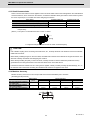
When using a power regenerative power supply unit, always install an AC reactor for each power supply
unit.
In the main circuit power supply side of the unit, always install an appropriate circuit protector or contactor
for each unit. Circuit protector or contactor cannot be shared by several units.
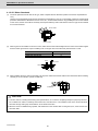
Always connect the motor to the drive unit's output terminals (U, V, W).
Do not directly connect a commercial power supply to the servo motor. Failure to observe this could result
in a fault.
When using an inductive load such as a relay, always connect a diode as a noise measure parallel to the
load.
When using a capacitance load such as a lamp, always connect a protective resistor as a noise measure
serial to the load.
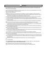
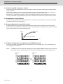
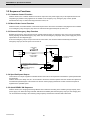
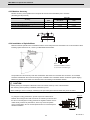
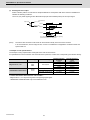
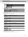
Servo drive unit
Do not reverse the direction of a diode which
COM
connect to a DC relay for the control output
(24VDC)
signals such as contractor and motor brake
output, etc. to suppress a surge. Connecting it
Control output
backwards could cause the drive unit to
signal
malfunction so that signals are not output, and
emergency stop and other safety circuits are inoperable.
Servo drive unit
COM
(24VDC)
RA
Control output
signal
RA
Do not connect/disconnect the cables connected between the units while the power is ON.
Securely tighten the cable connector fixing screw or fixing mechanism. An insecure fixing could cause the
cable to fall off while the power is ON.
When using a shielded cable instructed in the instruction manual, always ground the cable with a cable
clamp, etc.
Always separate the signals wires from the drive wire and power line.
Use wires and cables that have a wire diameter, heat resistance and flexibility that conforms to the system.
(3) Trial operation and adjustment
Check and adjust each program and parameter before starting operation. Failure to do so could lead to
unforeseen operation of the machine.
Do not make remarkable adjustments and changes of parameter as the operation could become unstable.
The usable motor and unit combination is predetermined. Always check the combinations and parameters
before starting trial operation.
The direct-drive motor and linear servo motor do not have a stopping device such as magnetic brakes.
Install a stopping device on the machine side.
When using the linear servo motor for an unbalance axis, adjust the unbalance weight to 0 by installing an
air cylinder, etc. on the machine side. The unbalance weight disables the initial magnetic pole adjustment.
CAUTION
(4)
Usage methods
In abnormal state, install an external emergency stop circuit so that the operation can be stopped and
power shut off immediately.
Turn the power OFF immediately if smoke, abnormal noise or odors are generated from the unit or motor.
Do not disassemble or repair this product.
Never make modifications.
When an alarm occurs, the machine will start suddenly if an alarm reset (RST) is carried out while an
operation start signal (ST) is being input. Always confirm that the operation signal is OFF before carrying
out an alarm reset. Failure to do so could lead to accidents or injuries.
Reduce magnetic damage by installing a noise filter. The electronic devices used near the unit could be
affected by magnetic noise. Install a line noise filter, etc., if there is a risk of magnetic noise.
Use the unit, motor and regenerative resistor with the designated combination. Failure to do so could lead
to fires or trouble.
The brake (magnetic brake) of the servo motor are for holding, and must not be used for normal braking.
There may be cases when holding is not possible due to the magnetic brake's life, the machine
construction (when ball screw and servo motor are coupled via a timing belt, etc.) or the magnetic brake's
failure. Install a stop device to ensure safety on the machine side.
After changing the programs/parameters or after maintenance and inspection, always test the operation
before starting actual operation.
Do not enter the movable range of the machine during automatic operation. Never place body parts near or
touch the spindle during rotation.
Follow the power supply specification conditions given in each specification for the power (input voltage,
input frequency, tolerable sudden power failure time, etc.).
Set all bits to "0" if they are indicated as not used or empty in the explanation on the bits.
Do not use the dynamic brakes except during the emergency stop. Continued use of the dynamic brakes
could result in brake damage.
If a circuit protector for the main circuit power supply is shared by several units, the circuit protector may
not activate when a short-circuit fault occurs in a small capacity unit. This is dangerous, so never share the
circuit protector.
Mitsubishi spindle motor is dedicated to machine tools. Do not use for other purposes.
(5)
Troubleshooting
If a hazardous situation is predicted during power failure or product trouble, use a servo motor with
magnetic brakes or install an external brake mechanism.
Always turn the main circuit power of the motor OFF when an alarm occurs.
If an alarm occurs, remove the cause, and secure the safety before resetting the alarm.
CAUTION
(6) Maintenance, inspection and part replacement
Always backup the programs and parameters before starting maintenance or inspections.
The capacity of the electrolytic capacitor will drop over time due to self-discharging, etc. To prevent
secondary disasters due to failures, replacing this part every five years when used under a normal
environment is recommended. Contact the Service Center, Service Station, Sales Office or delayer for
repairs or part replacement.
Do not perform a megger test (insulation resistance measurement) during inspections.
If the battery low warning is issued, immediately replace the battery. Replace the batteries while applying
the drive unit's control power.
Do not short circuit, charge, overheat, incinerate or disassemble the battery.
For after-purchase servicing of the built-in motor, only the servicing parts for MITSUBISHI encoder can be
supplied. For the motor body, prepare the spare parts at the machine manufacturers.
For maintenance, part replacement, and services in case of failures in the built-in motor (including the
encoder), take necessary actions at the machine manufacturers. For drive unit, Mitsubishi can offer the
after-purchase servicing as with the general drive unit.
(7) Disposal
Take the batteries and backlights for LCD, etc., off from the controller, drive unit and motor, and dispose of
them as general industrial wastes.
Do not disassemble the unit or motor.
Dispose of the battery according to local laws.
Always return the secondary side (magnet side) of the linear servo motor to the Service Center or Service
Station.
When incinerating optical communication cable, hydrogen fluoride gas or hydrogen chloride gas which is
corrosive and harmful may be generated. For disposal of optical communication cable, request for
specialized industrial waste disposal services that has incineration facility for disposing hydrogen fluoride
gas or hydrogen chloride gas.
(8) Transportation
The unit and motor are precision parts and must be handled carefully.
According to a United Nations Advisory, the battery unit and battery must be transported according to the
rules set forth by the International Civil Aviation Organization (ICAO), International Air Transportation
Association (IATA), International Maritime Organization (IMO), and United States Department of
Transportation (DOT), etc.
(9) General precautions
The drawings given in this manual show the covers and safety partitions, etc., removed to provide a clearer
explanation. Always return the covers or partitions to their respective places before starting operation, and
always follow the instructions given in this manual.
Treatment of waste
The following two laws will apply when disposing of this product. Considerations must be made to each law.
The following laws are in effect in Japan. Thus, when using this product overseas, the local laws will have a
priority. If necessary, indicate or notify these laws to the final user of the product.
(1) Requirements for "Law for Promotion of Effective Utilization of Resources"
(a) Recycle as much of this product as possible when finished with use.
(b) When recycling, often parts are sorted into steel scraps and electric parts, etc., and sold to scrap
contractors. Mitsubishi recommends sorting the product and selling the members to appropriate
contractors.
(2) Requirements for "Law for Treatment of Waste and Cleaning"
(a) Mitsubishi recommends recycling and selling the product when no longer needed according to item
(1) above. The user should make an effort to reduce waste in this manner.
(b) When disposing a product that cannot be resold, it shall be treated as a waste product.
(c) The treatment of industrial waste must be commissioned to a licensed industrial waste treatment
contractor, and appropriate measures, including a manifest control, must be taken.
(d) Batteries correspond to "primary batteries", and must be disposed of according to local disposal
laws.
Disposal
(Note)
This symbol mark is for EU countries only.
This symbol mark is according to the directive 2006/66/EC Article 20 Information for endusers and Annex II.
Your MITSUBISHI ELECTRIC product is designed and manufactured with high quality materials and
components which can be recycled and/or reused.
This symbol means that batteries and accumulators, at their end-of-life, should be disposed of
separately from your household waste.
If a chemical symbol is printed beneath the symbol shown above, this chemical symbol means that the
battery or accumulator contains a heavy metal at a certain concentration. This will be indicated as
follows:
Hg: mercury (0,0005%), Cd: cadmium (0,002%), Pb: lead (0,004%)
In the European Union there are separate collection systems for used batteries and accumulators.
Please, dispose of batteries and accumulators correctly at your local community waste collection/
recycling centre.
Please, help us to conserve the environment we live in!
Trademarks
MELDAS, MELSEC, EZSocket, EZMotion, iQ Platform, MELSOFT, GOT, CC-Link, CC-Link/LT and CC-Link
IE are either trademarks or registered trademarks of Mitsubishi Electric Corporation in Japan and/or other
countries.
Other company and product names that appear in this manual are trademarks or registered trademarks of the
respective companies.
本製品の取扱いについて
( 日本語 /Japanese)
本製品は工業用 ( クラス A) 電磁環境適合機器です。販売者あるいは使用者はこの点に注意し、住商業環境以外で
の使用をお願いいたします。
Handling of our product
(English)
This is a class A product. In a domestic environment this product may cause radio interference in which case the
user may be required to take adequate measures.
본 제품의 취급에 대해서
( 한국어 /Korean)
이 기기는 업무용 (A 급 ) 전자파적합기기로서 판매자 또는 사용자는 이 점을 주의하시기 바라며 가정외의 지역에
서 사용하는 것을 목적으로 합니다 .
WARRANTY
Please confirm the following product warranty details before using MITSUBISHI CNC.
1. Warranty Period and Coverage
Should any fault or defect (hereafter called "failure") for which we are liable occur in this product during the warranty period,
we shall provide repair services at no cost through the distributor from which the product was purchased or through a
Mitsubishi Electric service provider. Note, however that this shall not apply if the customer was informed prior to purchase of
the product that the product is not covered under warranty. Also note that we are not responsible for any on-site readjustment
and/or trial run that may be required after a defective unit is replaced.
[Warranty Term]
The term of warranty for this product shall be twenty-four (24) months from the date of delivery of product to the end user,
provided the product purchased from us in Japan is installed in Japan (but in no event longer than thirty (30) months,
Including the distribution time after shipment from Mitsubishi Electric or its distributor).
Note that, for the case where the product purchased from us in or outside Japan is exported and installed in any country
other than where it was purchased; please refer to "2. Service in overseas countries" as will be explained.
[Limitations]
(1) The customer is requested to conduct an initial failure diagnosis by him/herself, as a general rule. It can also be carried
out by us or our service provider upon the customer’s request and the actual cost will be charged.
(2) This warranty applies only when the conditions, method, environment, etc., of use are in compliance with the terms and
conditions and instructions that are set forth in the instruction manual, user’s manual, and the caution label affixed to the
product, etc.
(3) Even during the term of warranty, repair costs shall be charged to the customer in the following cases:
(a) a failure caused by improper storage or handling, carelessness or negligence, etc., or a failure caused by the
customer’s hardware or software problem
(b) a failure caused by any alteration, etc., to the product made by the customer without Mitsubishi Electric’s approval
(c) a failure which may be regarded as avoidable, if the customer’s equipment in which this product is incorporated is
equipped with a safety device required by applicable laws or has any function or structure considered to be
indispensable in the light of common sense in the industry
(d) a failure which may be regarded as avoidable if consumable parts designated in the instruction manual, etc. are duly
maintained and replaced
(e) any replacement of consumable parts (including a battery, relay and fuse)
(f) a failure caused by external factors such as inevitable accidents, including without limitation fire and abnormal
fluctuation of voltage, and acts of God, including without limitation earthquake, lightning, and natural disasters
(g) a failure which is unforeseeable under technologies available at the time of shipment of this product from our company
(h) any other failures which we are not responsible for or which the customer acknowledges we are not responsible for
2. Service in Overseas Countries
If the customer installs the product purchased from us in his/her machine or equipment, and export it to any country other
than where he/she bought it, the customer may sign a paid warranty contract with our local FA center.
This falls under the case where the product purchased from us in or outside Japan is exported and installed in any country
other than where it was purchased.
For details please contact the distributor from which the customer purchased the product.
3. Exclusion of Responsibility for Compensation against Loss of Opportunity, Secondary Loss, etc.
Whether during or after the term of warranty, we assume no responsibility for any damages arising from causes for which we
are not responsible, any losses of opportunity and/or profit incurred by the customer due to a failure of this product, any
damages, secondary damages or compensation for accidents arising under specific circumstances that either foreseen or
unforeseen by Mitsubishi Electric, any damages to products other than this product, or compensation for any replacement
work, readjustment and startup test run of on-site machines or any other operations conducted by the customer.
4. Changes in Product Specifications
Specifications shown in our catalogs, manuals or technical documents are subject to change without notice.
5. Product Application
(1) For the use of this product, its applications should be those that may not result in a serious damage even if any failure or
malfunction occurs in the product, and a backup or fail-safe function should operate on an external system to the product
when any failure or malfunction occurs.
(2) Mitsubishi CNC is designed and manufactured solely for applications to machine tools to be used for industrial purposes.
Do not use this product in any applications other than those specified above, especially those which are substantially
influential on the public interest or which are expected to have significant influence on human lives or properties.
Contents
1 Introduction ................................................................................................................................................. 1
1.1 Servo/Spindle Drive System Configuration............................................................................................ 2
1.1.1 System Configuration..................................................................................................................... 2
1.2 Explanation of Type ............................................................................................................................... 3
1.2.1 Servo Motor Type .......................................................................................................................... 3
1.2.2 Servo Drive Unit Type.................................................................................................................... 4
1.2.3 Spindle Motor Type........................................................................................................................ 5
1.2.4 AC Reactor Type ........................................................................................................................... 6
2 Specifications.............................................................................................................................................. 7
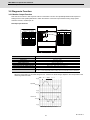
2.1 Servo Motor ........................................................................................................................................... 8
2.1.1 Specifications List .......................................................................................................................... 8
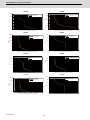
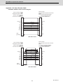
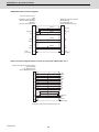
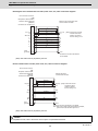
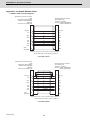
2.1.2 Torque Characteristics................................................................................................................. 10
2.2 Spindle Motor....................................................................................................................................... 12
2.2.1 Specifications............................................................................................................................... 12
2.2.2 Output Characteristics ................................................................................................................. 20
2.3 Drive Unit ............................................................................................................................................. 25
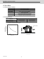
2.3.1 Installation Environment Conditions............................................................................................. 25
2.3.2 Multi Axis Integrated Drive Unit.................................................................................................... 26
2.3.3 Unit Outline Dimension Drawing .................................................................................................. 26
2.3.4 AC Reactor .................................................................................................................................. 27
2.3.5 Explanation of Each Part ............................................................................................................. 28
3 Function Specifications............................................................................................................................ 29
3.1 Function Specifications List ................................................................................................................. 30
3.1 Base Control Functions........................................................................................................................ 33
3.1.1 Full Closed Loop Control ............................................................................................................. 33
3.1.2 Position Command Synchronous Control .................................................................................... 34
3.1.3 Speed Command Synchronous Control ...................................................................................... 34
3.1.4 Distance-coded Reference Position Control ................................................................................ 35
3.1.5 Spindle's Continuous Position Loop Control................................................................................ 35
3.1.6 Coil Changeover Control.............................................................................................................. 35
3.1.7 Gear Changeover Control............................................................................................................ 35
3.1.8 Orientation Control....................................................................................................................... 35
3.1.9 Indexing Control........................................................................................................................... 35
3.1.10 Synchronous Tapping Control ................................................................................................... 36
3.1.11 Spindle Synchronous Control .................................................................................................... 36
3.1.12 Spindle/C Axis Control ............................................................................................................... 36
3.1.13 Proximity Switch Orientation Control ......................................................................................... 36
3.1.14 Power Regeneration Control...................................................................................................... 36
3.1.15 Resistor Regeneration Control................................................................................................... 36
3.2 Servo/Spindle Control Functions ......................................................................................................... 37
3.2.1 Torque Limit Function .................................................................................................................. 37
3.2.2 Variable Speed Loop Gain Control .............................................................................................. 37
3.2.3 Gain Changeover for Synchronous Tapping Control ................................................................... 37
3.2.4 Speed Loop PID Changeover Control ......................................................................................... 38
3.2.5 Disturbance Torque Observer...................................................................................................... 38
3.2.6 Smooth High Gain Control (SHG Control) ................................................................................... 38
3.2.7 High-speed Synchronous Tapping Control (OMR-DD Control) ................................................... 38
3.2.8 Dual Feedback Control ................................................................................................................ 39
3.2.9 HAS Control ................................................................................................................................. 39
3.2.10 OMR-FF Control ........................................................................................................................ 40
3.2.11 Control Loop Gain Changeover ................................................................................................. 40
3.2.12 Spindle Output Stabilizing Control ............................................................................................. 40
3.2.13 High-response Spindle Acceleration/Deceleration Function...................................................... 40
3.3 Compensation Control Function .......................................................................................................... 41
3.3.1 Jitter Compensation ..................................................................................................................... 41
3.3.2 Notch Filter................................................................................................................................... 41
3.3.3 Adaptive Tracking-type Notch Filter............................................................................................. 41
3.3.4 Overshooting Compensation ....................................................................................................... 42
3.3.5 Machine End Compensation Control ........................................................................................... 42
3.3.6 Lost Motion Compensation Type 2 .............................................................................................. 43
3.3.7 Lost Motion Compensation Type 3 .............................................................................................. 43
3.3.8 Lost Motion Compensation Type 4 .............................................................................................. 44
3.3.9 Spindle Motor Temperature Compensation Function .................................................................. 44
3.4 Protection Function .............................................................................................................................. 45
3.4.1 Deceleration Control at Emergency Stop..................................................................................... 45
3.4.2 Vertical Axis Drop Prevention/Pull-up Control ............................................................................. 45
3.4.3 Earth Fault Detection ................................................................................................................... 45
3.4.4 Collision Detection Function ........................................................................................................ 46
3.4.5 SLS (Safely Limited Speed) Function .......................................................................................... 46
3.4.6 Fan Stop Detection ...................................................................................................................... 46
3.4.7 Open-phase Detection ................................................................................................................. 46
3.4.8 Contactor Weld Detection ............................................................................................................ 46
3.4.9 STO (Safe Torque Off) Function.................................................................................................. 47
3.4.10 SBC (Safe Brake Control) Function ........................................................................................... 48
3.4.11 Deceleration and Stop Function at Power Failure ..................................................................... 49
3.4.12 Retraction Function at Power Failure......................................................................................... 49
3.5 Sequence Functions ............................................................................................................................ 50
3.5.1 Contactor Control Function .......................................................................................................... 50
3.5.2 Motor Brake Control Function ...................................................................................................... 50
3.5.3 External Emergency Stop Function ............................................................................................. 50
3.5.4 Specified Speed Output ............................................................................................................... 50
3.5.5 Quick READY ON Sequence....................................................................................................... 50
3.6 Diagnosis Function............................................................................................................................... 51
3.6.1 Monitor Output Function .............................................................................................................. 51
3.6.2 Machine Resonance Frequency Display Function....................................................................... 52
3.6.3 Machine Inertia Display Function................................................................................................. 52
3.6.4 Motor Temperature Display Function........................................................................................... 52
3.6.5 Load Monitor Output Function ..................................................................................................... 52
3.6.6 Open Loop Control Function........................................................................................................ 52
3.6.7 Power Supply Diagnosis Display Function .................................................................................. 52
4 Characteristics .......................................................................................................................................... 53
4.1 Servo Motor.......................................................................................................................................... 54
4.1.1 Environmental Conditions ........................................................................................................... 54
4.1.2 Quakeproof Level......................................................................................................................... 54
4.1.3 Shaft Characteristics.................................................................................................................... 55
4.1.4 Machine Accuracy........................................................................................................................ 55
4.1.5 Oil / Water Standards................................................................................................................... 56
4.1.6 Installation of Servo Motor ........................................................................................................... 57
4.1.7 Overload Protection Characteristics ............................................................................................ 57
4.1.8 Magnetic Brake ............................................................................................................................ 59
4.1.9 Dynamic Brake Characteristics ................................................................................................... 62
4.2 Spindle Motor ....................................................................................................................................... 64
4.2.1 Environmental Conditions ........................................................................................................... 64
4.2.2 Shaft Characteristics.................................................................................................................... 64
4.2.3 Machine Accuracy........................................................................................................................ 65
4.2.4 Installation of Spindle Motor......................................................................................................... 65
4.3 Drive Unit ............................................................................................................................................. 66
4.3.1 Environmental Conditions ........................................................................................................... 66
4.3.2 Heating Value .............................................................................................................................. 66
5 Dedicated Options .................................................................................................................................... 67
5.1 Servo Options ...................................................................................................................................... 68
5.1.1 Battery Option (MR-BAT6V1SET, MDSBTBOX-LR2060) ........................................................... 70
5.1.2 Ball Screw Side Encoder (OSA105ET2A) ................................................................................... 74
5.1.3 Machine Side Encoder................................................................................................................. 76
5.1.4 Twin-head Magnetic Encoder (MBA Series)................................................................................ 81
5.2 Spindle Options.................................................................................................................................... 85
5.2.1 Spindle Side ABZ Pulse Output Encoder (OSE-1024 Series) ..................................................... 86
5.2.2 Spindle Side PLG Serial Output Encoder (TS5690, MU1606 Series) ......................................... 88
5.2.3 Twin-head Magnetic Encoder (MBE Series)................................................................................ 92
5.2.4 Spindle Side Accuracy Serial Output Encoder (ERM280, MPCI Series)
(Other Manufacturer's Product) ................................................................................................... 96
5.2.5 Machine Side Encoder................................................................................................................. 96
5.3 Encoder Interface Unit ......................................................................................................................... 97
5.3.1 Serial Output Interface Unit for ABZ Analog Encoder MDS-B-HR............................................... 97
5.3.2 Serial Output Interface Unit for ABZ Analog Encoder EIB192M
(Other Manufacturer's Product) ................................................................................................. 100
5.3.3 Serial Output Interface Unit for ABZ Analog Encoder EIB392M
(Other Manufacturer's Product) ................................................................................................. 101
5.3.4 Serial Output Interface Unit for ABZ Analog Encoder ADB-20J Series
(Other Manufacturer's Product) ................................................................................................. 102
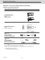
5.4 Cables and Connectors ..................................................................................................................... 103
5.4.1 Cable Connection Diagram........................................................................................................ 103
5.4.2 List of Cables and Connectors................................................................................................... 104
5.4.3 Optical Communication Cable Specifications ............................................................................ 110
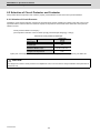
6 Specifications of Peripheral Devices .................................................................................................... 113
6.1 Selection of Wire................................................................................................................................ 114
6.1.1 Example of Wires by Unit........................................................................................................... 114
6.2 Selection of Circuit Protector and Contactor...................................................................................... 116
6.2.1 Selection of Circuit Protector ..................................................................................................... 116
6.2.2 Selection of Contactor................................................................................................................ 117
6.3 Selection of Earth Leakage Breaker .................................................................................................. 118
6.4 Noise Filter......................................................................................................................................... 119
6.5 Surge Absorber.................................................................................................................................. 120
6.6 Relay.................................................................................................................................................. 121
6.7 Selection of Link Bar .......................................................................................................................... 123
6.7.1 Wire Size for L11 and L21 Link Bar ........................................................................................... 123
6.7.2 Wire Size for L+ and L- Link Bar................................................................................................ 123
7 Selection .................................................................................................................................................. 125
7.1 Selection of the Servo Motor.............................................................................................................. 126
7.1.1 Outline ....................................................................................................................................... 126
7.1.2 Selection of Servo Motor Capacity............................................................................................. 127
7.1.3 Motor Shaft Conversion Load Torque........................................................................................ 134
7.1.4 Expressions for Load Inertia Calculation ................................................................................... 135
7.2 Selection of the Spindle Motor ........................................................................................................... 136
7.3 Selection of the Additional Axis Drive Unit......................................................................................... 137
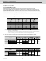
7.3.1 Calculation of Spindle Output .................................................................................................... 137
7.3.2 Calculation of Servo Motor Output............................................................................................. 139
7.3.3 Selection of the Additional Axis Drive Unit................................................................................. 140
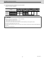
7.3.4 Required Capacity of Power Supply .......................................................................................... 141
7.3.5 Example for Additional Axis Drive Unit and Power Supply Facility Capacity ............................. 142
Appendix 1 Cable and Connector Specifications ................................................................................... 143
Appendix 1.1 Selection of Cable.............................................................................................................. 144
Appendix 1.1.1 Cable Wire and Assembly.......................................................................................... 144
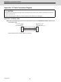
Appendix 1.2 Cable Connection Diagram................................................................................................ 146
Appendix 1.2.1 Battery Cable ............................................................................................................. 146
Appendix 1.2.2 Servo Encoder Cable................................................................................................. 147
Appendix 1.2.3 Spindle Encoder Cable .............................................................................................. 150
Appendix 1.2.4 Twin-head Magnetic Encoder Cable.......................................................................... 152
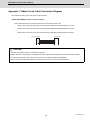
Appendix 1.3 Main Circuit Cable Connection Diagram ............................................................................ 153
Appendix 1.4 Connector Outline Dimension Drawings ............................................................................ 154
Appendix 1.4.1 Connector for Drive Unit ............................................................................................ 154
Appendix 1.4.2 Connector for Servo................................................................................................... 158
Appendix 1.4.3 Connector for Spindle ................................................................................................ 160
Appendix 2 Restrictions for Lithium Batteries ........................................................................................ 163
Appendix 2.1 Restriction for Packing ....................................................................................................... 164
Appendix 2.1.1 Target Products ......................................................................................................... 164
Appendix 2.1.2 Handling by User ....................................................................................................... 165
Appendix 2.1.3 Reference .................................................................................................................. 165
Appendix 2.2 Products Information Data Sheet (ER Battery) .................................................................. 166
Appendix 2.3 Forbiddance of Transporting Lithium Battery by Passenger Aircraft Provided in the
Code of Federal Regulation ............................................................................................... 168
Appendix 2.4 California Code of Regulation "Best Management Practices for Perchlorate Materials" ... 168
Appendix 2.5 Restriction Related to EU Battery Directive ....................................................................... 169
Appendix 2.5.1 Important Notes ......................................................................................................... 169
Appendix 2.5.2 Information for End-user ............................................................................................ 169
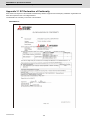
Appendix 3 EC Declaration of Conformity............................................................................................... 171
Appendix 3.1 EC Declaration of Conformity............................................................................................. 172
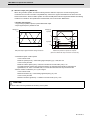
Outline for MDS-EM Series
Instruction Manual (IB-1501241-A)
2.8.3 Spindle Coil Changeover
2.8.4 Proximity Switch Orientation
3 Safety Function
1 Installation
3.1 Safety Function
1.1 Installation of Servo Motor
3.1.1 Harmonized Standard
1.1.1 Environmental Conditions
3.1.2 Outline of Safety Function
1.1.2 Quakeproof Level
3.2 STO (Safe Torque Off) Function
1.1.3 Cautions for Mounting Load (Prevention of Impact
3.3 SBC (Safe Brake Control) Function
on Shaft)
4 Setup
1.1.4 Installation Direction
4.1 Initial Setup
1.1.5 Shaft Characteristics
4.1.1 Setting the Rotary Switch
1.1.6 Machine Accuracy
4.1.2 Transition of LED Display After Power Is Turned
1.1.7 Coupling with the Load
ON
1.1.8 Oil / Water Standards
4.2 Setting the Initial Parameters for the Servo Drive Unit
1.1.9 Installation of Servo Motor
4.2.1 Setting of Servo Specification Parameters
1.1.10 Cable Stress
4.2.2 Setting of Machine Side Encoder
1.2 Installation of Spindle Motor
4.2.3 Setting of Distance-coded Reference Scale
1.2.1 Environmental Conditions
4.2.4 List of Standard Parameters for Each Servo Motor
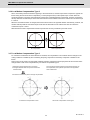
1.2.2 Balancing the Spindle Motor (Unit)
4.2.5 Servo Parameters
1.2.3 Shaft Characteristics
4.3 Setting the Initial Parameters for the Spindle Drive Unit
1.2.4 Machine Accuracy
4.3.1 Setting of Parameters Related to the Spindle
1.2.5 Coupling with the Fittings
4.3.2 List of Standard Parameters for Each Spindle Mo1.2.6 Ambient Environment
tor
1.2.7 Installation of Spindle Motor
4.3.3 Spindle Specification Parameters
1.2.8 Connection
4.3.4 Spindle Parameters
1.2.9 Cable Stress
5 Servo Adjustment
1.3 Installation of the Drive Unit
5.1 Servo Adjustment Procedure
1.3.1 Environmental Conditions
5.2 Gain Adjustment
1.3.2 Installation Direction and Clearance
5.2.1 Current Loop Gain
1.3.3 Prevention of Entering of Foreign Matter
5.2.2 Speed Loop Gain
1.3.4 Panel Installation Hole Work Drawings (Panel Cut
5.2.3 Position Loop Gain
Drawings)
5.2.4 OMR-FF Function
1.3.5 Heating Value
5.3
Characteristics Improvement
1.3.6 Heat Radiation Countermeasures
5.3.1 Optimal Adjustment of Cycle Time
1.4 Installation of the Machine End Encoder
5.3.2 Vibration Suppression Measures
1.4.1 Spindle Side ABZ Pulse Output Encoder (OSE5.3.3 Improving the Cutting Surface Precision
1024 Series)
5.3.4 Improvement of Characteristics during Accelera1.4.2 Spindle Side PLG Serial Output Encoder
tion/Deceleration
(TS5690, MU1606 Series)
5.3.5 Improvement of Protrusion at Quadrant Change1.4.3 Twin-head Magnetic Encoder (MBA405W,
over
MBE405W Series)
5.3.6 Improvement of Overshooting
1.5 Noise Measures
5.3.7 Improvement of the Interpolation Control Path
2 Wiring and Connection
5.4 Adjustment during Full Closed Loop Control
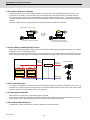
2.1 Part System Connection Diagram
5.4.1 Outline
2.2 Main Circuit Terminal Block/Control Circuit Connector
5.4.2 Speed Loop Delay Compensation
2.2.1 Names and Applications of Main Circuit Terminal
5.4.3 Dual Feedback Control
Block Signals and
5.5 Settings for Emergency Stop
Control Circuit Connectors
5.5.1 Deceleration Control
2.2.2 Connector Pin Assignment
5.5.2 Vertical Axis Drop Prevention Control
2.2.3 Main Circuit Connector (TE1) Wiring Method
5.5.3 Vertical Axis Pull-up Control
2.3 NC and Drive Unit Connection
5.6 Protective Functions
2.4 Motor and Encoder Connection
5.6.1 Overload Detection
2.4.1 Connection of the Servo Motor
5.6.2 Excessive Error Detection
2.4.2 Connection of the Full-closed Loop System
5.6.3 Collision Detection Function
2.4.3 Connection of the Spindle Motor
5.7 Servo Control Signal
2.5 Connection of Power Supply
5.7.1 Servo Control Input (NC to Servo)
2.5.1 Power Supply Input Connection
5.7.2 Servo Control Output (Servo to NC)
2.5.2 Connecting the Grounding Cable
6
Spindle
Adjustment
2.6 Wiring of the Motor Brake
6.1
Adjustment
Procedures for Each Control
2.6.1 Wiring of the Motor Magnetic Brake
6.1.1
Basic
Adjustments
2.7 Emergency Stop Observation
6.1.2 Gain Adjustment
2.8 Peripheral Control Wiring
6.1.3 Adjusting the Acceleration/Deceleration Opera2.8.1 Input/output Circuit Wiring
tion
2.8.2 Specified Speed Output
6.1.4 Orientation Adjustment
Appendix 4.4.1 Measures for Control Panel Unit
6.1.5 Synchronous Tapping Adjustment
Appendix 4.4.2 Measures for Door
6.1.6 High-speed Synchronous Tapping
Appendix 4.4.3 Measures for Operation Board Panel
6.1.7 Spindle C Axis Adjustment (For Lathe System)
Appendix 4.4.4 Shielding of the Power Supply Input
6.1.8 Spindle Synchronization Adjustment (For Lathe
Section
System)
Appendix 4.5 Measures for Various Cables
6.1.9 Deceleration Coil Changeover Valid Function by
Appendix 4.5.1 Measures for Wiring in Panel
Emergency Stop
Appendix 4.5.2 Measures for Shield Treatment
6.1.10 High-response Acceleration/Deceleration FuncAppendix 4.5.3 Servo/Spindle Motor Power Cable
tion
Appendix 4.5.4 Servo/Spindle Motor Feedback Cable
6.1.11 Spindle Cutting Withstand Level Improvement
Appendix 4.6 EMC Countermeasure Parts
6.1.12 Spindle Motor Temperature Compensation
Appendix 4.6.1 Shield Clamp Fitting
Function
Appendix 4.6.2 Ferrite Core
6.2 Settings for Emergency Stop
Appendix 4.6.3 Power Line Filter
6.2.1 Deceleration Control
Appendix 4.6.4 Surge Absorber
6.3 Spindle Control Signal
Appendix 5 Higher Harmonic Suppression Measure
6.3.1 Spindle Control Input (NC to Spindle)
Guidelines
6.3.2 Spindle Control Output (Spindle to NC)
Appendix 5.1 Higher Harmonic Suppression Measure
7 Troubleshooting
Guidelines
7.1 Points of Caution and Confirmation
Appendix 5.1.1 Calculating the Equivalent Capacity of
7.1.1 LED Display When Alarm or Warning Occurs
the Higher Harmonic Generator
7.2 Protective Functions List of Units
7.2.1 List of Alarms
7.2.2 List of Warnings
7.3 Troubleshooting
7.3.1 Troubleshooting at Power ON
7.3.2 Troubleshooting for Each Alarm No.
7.3.3 Troubleshooting for Each Warning No.
7.3.4 Parameter Numbers during Initial Parameter Error
7.3.5 Troubleshooting the Spindle System When There
Is No Alarm or Warning
8 Maintenance
8.1 Periodic Inspections
8.1.1 Inspections
8.1.2 Cleaning of Spindle Motor
8.2 Service Parts
8.3 Adding and Replacing Units and Parts
8.3.1 Replacing the Drive Unit
8.3.2 Replacing the Battery
Appendix 1 Cable and Connector Assembly
Appendix 1.1 CMV1-xPxxS-xx Plug Connector
Appendix 1.2 1747464-1 Plug Connector
Appendix 1.2.1 Applicable Products
Appendix 1.2.2 Applicable Cable
Appendix 1.2.3 Related Documents
Appendix 1.2.4 Assembly Procedure
Appendix 2 D/A Output Specifications for Drive Unit
Appendix 2.1 D/A Output Specifications
Appendix 2.2 Output Data Settings
Appendix 2.2.1 Servo Drive Unit Settings
Appendix 2.2.2 Spindle Drive Unit Settings
Appendix 2.3 Setting the Output Magnification
Appendix 2.3.1 Servo Drive Unit Settings
Appendix 2.3.2 Spindle Drive Unit Settings
Appendix 3 Compliance to EC Directives
Appendix 3.1 Compliance to EC Directives
Appendix 3.1.1 European EC Directives
Appendix 3.1.2 Cautions for EC Directive Compliance
Appendix 4 EMC Installation Guidelines
Appendix 4.1 Introduction
Appendix 4.2 EMC Instructions
Appendix 4.3 EMC Measures
Appendix 4.4 Measures for Panel Structure
1
Introduction
1
IB-1501238-A
MDS-EM Series Specifications Manual
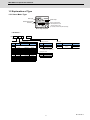
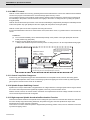
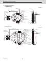
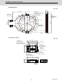
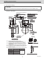
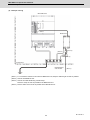
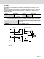
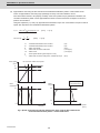
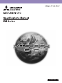
1 Introduction
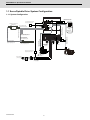
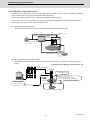
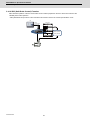
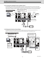
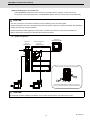
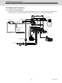
1.1 Servo/Spindle Drive System Configuration
1.1.1 System Configuration
CN9B
RA circuit for motor brake
(Note) Prepared by user.
CN9A
DOCOM
DO(ALM)
LG
+5V
LG
BT(3.6V)
CH1
CN2L
CN2M
CN2S
Optical communication cable
Power
connector
Brake cable
Linear scale
(for full closed loop control)
(Note) Prepared by user.
䠄*Only connector is supplied䠅
Linear scale cable for M/S-axis
(Note) Prepared by user.
Servo encoder cable
< Linear scale cable >
(Note) Prepared by user.
Power cable
䠄*Only connector
is supplied䠅
BTO1
BTO2
BTO3
CH2
Battery box
(MDS-BTBOX-LR2060)
CN3L
CN3M
CN3S
Servo encoder cable
<Motor side encoder cable>
Mitsubishi serial signal output
ABZ SIN wave signal output
Servo encoder cable
< Linear scale cable for MDS-B-HR >
(Note) Prepared by user.
OPT1A
CN2SP
CN3SP
Spindle encoder cable
< Spindle side encoder cable >
From NC
Servo encoder cable
<MDS-B-HR unit cable >
<Battery option>
BTI
BTO
CN22
To servo for
M-axis
To servo for
S-axis
Spindle side
encoder
<Built in cell battery>
Cell battery built in
drive unit
(MDS-BAT6V1SET)
Spindle encoder cable
< Motor side PLG cable >
24V stabilized power supply
(Note) Prepared by user.
Encoder conversion unit
(MDS-B-HR)
RA circuit for contactor drive
(Note) Prepared by user.
Servomotor
Power connector
Brake connector
3-phase 200VAC
power supply
Circuit protector
(Note) Prepared
by user.
IB-1501238-A
AC reactor
Contactor
(Note) Prepared
by user.
2
Spindle motor
MDS-EM Series Specifications Manual
1 Introduction
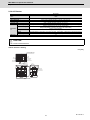
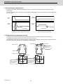
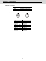
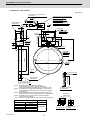
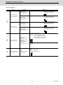
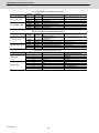
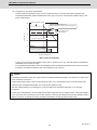
1.2 Explanation of Type
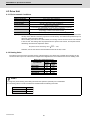
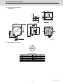
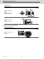
1.2.1 Servo Motor Type
Motor type
Rated output
Rated rotation speed
Serial No.
Date of manufacture
•109:September, 2010
•13Y:November, 2013
(X:October,Y:November,Z:December)
Motor rating nameplate
< HG Series >
HG
(1)
(2)
(3)
-
(4)
(1) Rated output · Maximum rotation speed
Maximum rotation
Symbol Rated output
Flange size (mm)
speed
75
under development
105
54
0.5 kW
4000 r/min
130 SQ.
104
1.0 kW
4000 r/min
130 SQ.
154
1.5 kW
4000 r/min
130 SQ.
224
2.2 kW
4000 r/min
130 SQ.
204
2.0 kW
4000 r/min
176 SQ.
354
3.5 kW
4000 r/min
176 SQ.
123
1.2 kW
3000 r/min
130 SQ.
223
2.2 kW
3000 r/min
130 SQ.
303
3.0 kW
3000 r/min
176 SQ.
453
4.5 kW
3500 r/min
176 SQ.
142
1.4 kW
2000 r/min
130 SQ.
302
3.0 kW
2000 r/min
176 SQ.
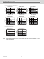
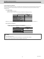
(3) Shaft end structure
Symbol
(4) Encoder
Shaft end structure
S
Straight
T
Taper
(Note) "Taper" is available for the
motor whose flange size is
90 SQ. mm or 130 SQ. mm.
(2) Magnetic brake
Symbol
Magnetic brake
None
None
B
With magnetic brakes
3
Symbol
Resolution
Detection method
Absolute
position
D48
D51
1,048,576 p/rev
4,194,304 p/rev
IB-1501238-A
MDS-EM Series Specifications Manual
1 Introduction
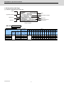
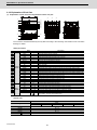
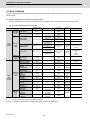
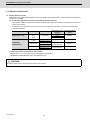
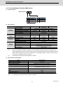
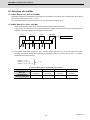
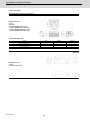
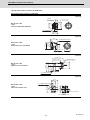
1.2.2 Servo Drive Unit Type
(1) Multi axis integrated servo drive unit
Output
Type
Applicable standard
Input/output conditions
Software No.
Manual No.
Date of manufacture
(Year-Month)
Serial No.
Rating nameplate
(1)
MDS-EM(1) Unit Type
MDS-EMUnit
width
SPV3-10040
SPV3-10080
SPV3-16080
SPV3-20080
SPV3-200120
Unit
nominal
maximum
current
40+40+40A
80+80+80A
260mm 80+80+80A
80+80+80A
120+120+120
75
105
54
104
154
224
HG □
204 354
123
223
(N ・ m) 2.0
3.0
2.9
5.9
9.0
12.0 13.7 22.5
7.0
12.0 22.5 37.2 11.0 20.0
●
●
●
●
●
●
●
●
●
●
●
●
●
●
●
●
●
●
●
●
●
●
●
●
●
●
●
●
Compatible
motor type
Stall torque
453
142
302
Axis
LMS
LM
LM
LMS
LM
under
development
● Indicates the compatible motor for each servo drive unit.
IB-1501238-A
303
4
●
●
●
●
●
●
●
MDS-EM Series Specifications Manual
1 Introduction
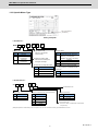
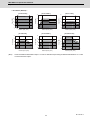
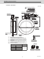
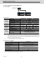
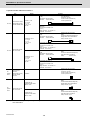
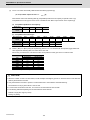
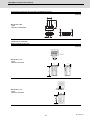
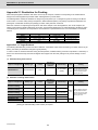
1.2.3 Spindle Motor Type
QR
code
Date of manufacture
(Year-Month)
Rating nameplate
< SJ-D Series >
(2) / (3) - (4)
SJ-D (1)
(1) Motor series
(6)
(4) Specification code
Symbol
Motor Series
None
Standard
J
Compact & lightweight
(6) Option (Note)
Symbol
Indicates a specification
code (01 to 99).
specifications
L
(5) -
None
unavailable, air-cooling, solid shaft)
(3) Maximum rotation speed
Low-inertia
specifications
Option
Standard (flange type, without oil
l
without
key, coil changeover
Indicates the hundreds place
C
and higher order digits.
J
Oil seal
X
Reversed cooling air
(2) Short time (or %ED) rated output
Symbol
Short-time rated output
With key
(Note) If more than one option is included,
the symbols are in alphabetical order.
5.5
5.5kW
(5) Encoder
7.5
7.5kW
Symbol
Type
11
11kW
None
Type 1
15
15kW
T
Type 2
< SJ-V/VL Series >
SJ- (1)
(2)
-
(3)
(4)
T
For MDS-E/EM motor
(1) Motor series
(2) Short time rated output (For normal specification)
(4) Special specification
Symbol
Motor series
Symbol Short time rated output
Symbol Special specifications
V
Medium-inertia series
5.5
5.5 kW
None
None
VL
Low-inertia series
7.5
7.5 kW
Z
High-speed
11
11 kW
15
15 kW
18.5
18.5 kW
(3) Specification code
The SJ-V/VL Series is indicated with a specification
code (01 to 99).
(Note) This explains the model name system of a spindle motor, and all combinations of motor types listed above do not exist.
5
IB-1501238-A
MDS-EM Series Specifications Manual
1 Introduction
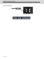
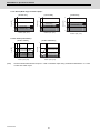
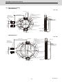
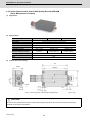
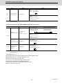
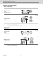
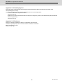
1.2.4 AC Reactor Type
Type
D-AL-18.5K
Nameplate
Top surface of AC reactor
IB-1501238-A
Type
Capacity
Compatible power supply unit
D-AL-18.5K
18.5kW
MDS-EM-SPV3 Series
6
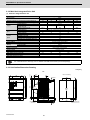
2
Specifications
7
IB-1501238-A
MDS-EM Series Specifications Manual
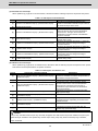
2 Specifications
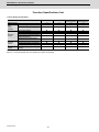
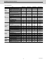
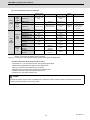
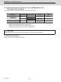
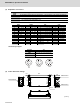
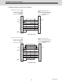
2.1 Servo Motor
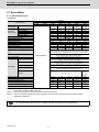
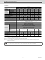
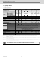
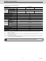
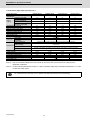
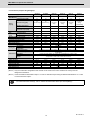
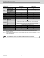
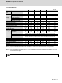
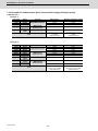
2.1.1 Specifications List
< HG Series >
HG Series
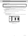
ABS specifications: HG □ -D51 / -D48
HG54
HG104
HG154
xxx80
xxx80
xxx80
200120
0.5
1.0
1.5
1.8
3.6
5.8
1.6
3.2
4.8
3.2
6.6
11.0
2.9
5.9
9.0
1.1
2.0
2.8
3000
4000
16.8
29.0
52.0
13.0
23.3
42.0
4.1
8.4
12.7
Servo motor type
HG75
Compatible
drive unit type
HG105
MDS-EM-SPV3-
Rated output [kW]
Rated current [A]
Continuous
Rated torque [N•m]
characteristics
Stall current [A]
Stall torque [N•m]
Power facility capacity [kVA]
Rated rotation speed [r/min]
Maximum rotation speed [r/min]
Maximum current [A]
Maximum torque [N•m]
Power rate at continuous rated torque [kW/s]
HG224
xxx80
200120
2.2
8.5
7.0
14.5
12.0
4.1
HG204
xxx80
200120
2.0
6.8
6.4
14.6
13.7
3.7
57.0
46.5
20.7
57.0
47.0
10.6
Motor inertia [kg•cm2]
6.1
11.9
17.8
23.7
38.3
Motor inertia with brake [kg•cm2]
8.3
14.1
20.0
25.9
48.0
High-speed, high-accuracy machine: 3 times or less of motor inertia
General machine tool (interpolation axis): 5 times or less of motor inertia
General machine (non-interpolation axis): 7 times or less of motor inertia
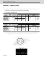
Resolution per motor revolution
D51:4,194,304 pulse/rev, D48:1,048,576 pulse/rev
IP67 (The shaft-through portion is excluded.)
Operation: 0 to 40°C (with no freezing),
Storage: -15°C to 70°C (with no freezing)
Operation: 80%RH or less (with no dew condensation),
Storage: 90%RH or less (with no dew condensation)
Indoors (no direct sunlight); no corrosive gas, inflammable gas, oil mist, or
dust
Operation: 1000 meters or less above sea level,
Storage: 10000 meters or less above sea level
Maximum motor shaft conversion load inertia
ratio
Motor side encoder
under development
Degree of protection
Ambient temperature
Ambient humidity
Atmosphere
Environment
Altitude
X:24.5m/s2
(2.5G)
X,Y:24.5m/s2 (2.5G)
Vibration
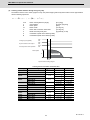
Flange size [mm]
Total length (excluding shaft) [mm] (Note 3)
Flange fitting diameter [mm]
Shaft diameter [mm]
130 SQ.
118.5
Φ110
Φ24
4.8/
6.8
155 (F)
Mass Without / with brake [kg]
Heat-resistant class
130 SQ.
140.5
Φ110
Φ24
6.5/
8.5
130 SQ.
162.5
Φ110
Φ24
8.3/
10.3
130 SQ.
184.5
Φ110
Φ24
10.0/
12.0
Y:29.4m/s2
(3G)
176 SQ.
143.5
Φ114.3
Φ35
12.0/
18.0
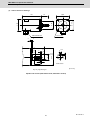
(Note 1) The above characteristics values are representative values. The maximum current and maximum torque are the
values when combined with the drive unit.
(Note 2) The total length will be 3.5mm longer when using an D51 encoder.
(Note 3) Only the combination designated in this manual can be used for the motor and drive unit. Always use the
designated combination.
For outline dimension drawings, refer to "DRIVE SYSTEM DATA BOOK (IB-1501252(ENG))".
IB-1501238-A
8
MDS-EM Series Specifications Manual
2 Specifications
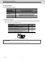
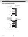
< HG Series >
HG Series
ABS specifications: HG □ -D51 / -D48
HG223
HG303
HG453
xxx80
xxx80
200120
200120
2.2
3.0
4.5
9.0
10.7
13.4
10.5
14.3
14.3
10.2
15.8
34.0
12.0
22.5
37.2
4.1
5.5
8.1
2000
3000
3000
3500
29.0
48.0
79.6
32.0
64.0
90.0
46.5
27.3
18.3
Servo motor type
Compatible
drive unit type
MDS-EM-SPV3-
Rated output [kW]
Rated current [A]
Continuous
Rated torque [N•m]
characteristics
Stall current [A]
Stall torque [N•m]
Power facility capacity [kVA]
Rated rotation speed [r/min]
Maximum rotation speed [r/min]
Maximum current [A]
Maximum torque [N•m]
Power rate at continuous rated torque [kW/s]
HG354
HG123
200120
10040
3.5
13.8
11.1
28.0
22.5
6.4
3000
4000
79.6
75.0
16.5
1.2
5.2
5.7
6.4
7.0
2.3
15.5
17.0
27.3
HG142
HG302
10040
xxx80
1.4
3.9
6.7
6.4
11.0
2.7
3.0
10.9
14.3
10.9
20.0
5.5
2000
2000
15.5
26.5
25.2
29.0
50.0
27.3
Motor inertia [kg•cm2]
75.0
11.9
23.7
75.0
112.0
17.8
75.0
Motor inertia with brake [kg•cm2]
84.7
14.1
25.9
84.7
121.7
20.0
84.7
High-speed, high-accuracy machine: 3 times or less of motor inertia
General machine tool (interpolation axis): 5 times or less of motor inertia
General machine (non-interpolation axis): 7 times or less of motor inertia
Resolution per motor revolution
D51:4,194,304 pulse/rev, D48:1,048,576 pulse/rev
IP67 (The shaft-through portion is excluded.)
Operation: 0 to 40°C (with no freezing),
Storage: -15°C to 70°C (with no freezing)
Operation: 80%RH or less (with no dew condensation),
Storage: 90%RH or less (with no dew condensation)
Indoors (no direct sunlight); no corrosive gas, inflammable gas, oil mist, or dust
Operation: 1000 meters or less above sea level,
Storage: 10000 meters or less above sea level
Maximum motor shaft conversion load inertia
ratio
Motor side encoder
Degree of protection
Ambient temperature
Ambient humidity
Atmosphere
Environment
Altitude
Vibration
Flange size [mm]
Total length (excluding shaft) [mm] (Note 3)
Flange fitting diameter [mm]
Shaft diameter [mm]
Mass Without / with brake [kg]
X:24.5m/s2
(2.5G)
Y:29.4m/s2
(3G)
176 SQ.
183.5
Φ114.3
Φ35
19.0/
25.0
2
X,Y:24.5m/s (2.5G)
130 SQ.
140.5
Φ110
Φ24
130 SQ.
184.5
Φ110
Φ24
10.0/
12.0
6.5/8.5
Heat-resistant class
X:24.5m/s2 (2.5G)
Y:29.4m/s2 (3G)
176 SQ.
183.5
Φ114.3
Φ35
19.0/
25.0
155 (F)
176 SQ.
223.5
Φ114.3
Φ35
26.0/
32.0
X, Y:24.5m/s2
(2.5G)
130 SQ.
162.5
Φ110
Φ24
8.3/10.3
X:24.5m/s2
(2.5G)
Y:29.4m/s2
(3G)
176 SQ.
183.5
Φ114.3
Φ35
19.0/
25.0
(Note 1) The above characteristics values are representative values. The maximum current and maximum torque are the
values when combined with the drive unit.
(Note 2) The total length will be 3.5mm longer when using an D51 encoder.
(Note 3) Only the combination designated in this manual can be used for the motor and drive unit. Always use the
designated combination.
For outline dimension drawings, refer to "DRIVE SYSTEM DATA BOOK (IB-1501252(ENG))" .
9
IB-1501238-A
MDS-EM Series Specifications Manual
2 Specifications
2.1.2 Torque Characteristics
< HG Series >
[ HG75 ]
[ HG105 ]
under development
under development
[ HG54 ]
[ HG104 ]
[ HG154 ]
12
20
40
9
Short time operation range
6
15
Short time operation range
10
3
5
2000
0
4000
0
Rotation speed [r/min]
40
40
30
Short time operation range
20
10
80
30
Short time operation range
20
0
Rotation speed [r/min]
2000
40
80
30
60
Short time operation range
20
3000
0
4000
[ HG303 ]
Short time operation range
40
20
Continuous
operation range
2000
0
Rotation speed [r/min]
10
Continuous
operation range
1000
Continuous operation range
0
4000
Torque [N㨯O?
Short time operation range
Rotation speed [r/min]
IB-1501238-A
Torque [N㨯m]
Torque [N㨯m]
15
0
2000
[ HG223 ]
20
5
Short time operation range
40
Rotation speed [r/min]
[ HG123 ]
10
60
20
0
4000
4000
[ HG354 ]
Continuous operation range
2000
2000
Rotation speed [r/min]
10
0
0
100
Continuous
operation range
(Note1)
Continuous operation range
0
4000
[ HG204 ]
50
Torque [N㨯m]
Torque [N㨯m]
[ HG224 ]
0
2000
Rotation speed [r/min]
50
0
Short time operation range
20
Continuous operation range
Torque [N㨯m]
0
30
10
Continuous operation range
0
Torque [N㨯m]
50
Torque [N㨯m]
25
Torque [N㨯m]
15
Continuous
operation range
0
0
1000
2000
Rotation speed [r/min]
3000
0
1000
2000
3000
Rotation speed [r/min]
The above graphs show the data when applied the input voltage of 200VAC. When the input voltage is
200VAC or less, the short time operation range is limited.
10
MDS-EM Series Specifications Manual
2 Specifications
< HG Series >
[ HG453 ]
[ HG142]
[ HG302 ]
30
60
125
75
Short time operation range
50
Torque [N㨯m]
Torque [N㨯m]
100
Torque =0㨯O?
24
18
Short time operation range
12
40
Short time operation range
20
6
25
Continuous operation range
0
Continuous operation range
0
0
1000
2000
3000 3500
Rotation speed [r/min]
(Note1)
0
Continuous operation range
1000
Rotation speed [r/min]
2000
0
0
1000
Rotation speed [r/min]
2000
The above graphs show the data when applied the input voltage of 200VAC. When the input voltage is
200VAC or less, the short time operation range is limited.
11
IB-1501238-A
MDS-EM Series Specifications Manual
2 Specifications
2.2 Spindle Motor
2.2.1 Specifications
< SJ-D Series (Normal) >
Spindle motor type[
Compatible drive unit
MDS-EM-SPV3Continuous rating [kW]
Short time rating [kW]
Output
capacity
SJ-D5.5/
100-01
SJ-D5.5/
120-01
SJ-D5.5/
120-02
100xx
100xx
3.7
5.5
(30-minute
rating)
3.7
5.5
(30-minute
rating)
5.5
5.5
7.5
9.2
9
11.04
100xx
16080
SJ-D7.5/
100-01
SJ-D7.5/
120-01
SJ-D11/
100-01
100xx
100xx
16080
5.5
7.5
(30-minute
rating)
5.5
7.5
(30-minute
rating)
7.5
11
(30-minute
rating)
10.4
7.5
7.5
11
12.48
9
9
13.2
13.4
1500
10000
A112
35.0
13.4
1500
12000
A112
35.0
19.6
1500
10000
B112
47.7
200xx
3.7
5.5
(25%ED rating)
Standard output during
acceleration/deceleration [kW]
Actual acceleration/
deceleration output [kW]
Power facility capacity [kVA]
Base rotation speed [r/min]
Maximum rotation speed [r/min]
Frame No.
Continuous rated torque [N•m]
6.6
6.6
9.9
1500
10000
D90
23.6
9.9
1500
12000
D90
23.6
GD2[kg•m2]
0.053
0.053
0.030
0.094
0.094
0.122
Motor inertia [kg•m2]
Tolerable radial load [N]
Input voltage
Cooling fan
Maximum power
consumption
Ambient temperature
0.013
0.013
0.0074
0.023
0.023
0.031
1470
1470
980
3-phase 200V
1960
1960
1960
38W
38W
38W
50W
50W
50W
Ambient humidity
Environment
Atmosphere
Altitude
Degree of protection
Flange size [mm]
Total length (excluding shaft) [mm]
Flange fitting diameter [mm]
Shaft diameter [mm]
Mass [kg]
Heat-resistant class
9.9
2800
12000
B90
12.6
Operation: 0 to 40°C (with no freezing), Storage: -20°C to 65°C (with no freezing)
Operation: 90%RH or less (with no dew condensation), Storage: 90%RH or less (with no dew
condensation)
Indoors (no direct sunlight); no corrosive gas, inflammable gas, oil mist, or dust
Operation: 1000 meters or less above sea level, Storage: 1000 meters or less above sea level,
Transportation: 10000 meters or less above sea level
IP54 (The shaft-through portion is excluded.)
174 SQ.
174 SQ.
174 SQ.
204 SQ.
180 SQ.
180 SQ.
417
417
327
439
439
489
Φ150
Φ150
Φ150
Φ180
Φ180
Φ180
Φ28
Φ28
Φ28
Φ32
Φ32
Φ48
39
39
26
53
53
64
155 (F)
(Note 1) The tolerable radial load is the value calculated at the center of output shaft.
(Note 2) Only the combination designated in this manual can be used for the motor and drive unit. Always use the
designated combination.
(Note 3) Actual acceleration/deceleration output is 1.2-fold of "Standard output during acceleration/deceleration" or 1.2-fold
of "Short time rated output".
(Note 4) For SJ-D5.5/120-02, output characteristics at acceleration/deceleration vary depending on the connected drive unit.
Refer to "output characteristics" for details.
For outline dimension drawings, refer to "DRIVE SYSTEM DATA BOOK (IB-1501252(ENG))".
IB-1501238-A
12
MDS-EM Series Specifications Manual
2 Specifications
< SJ-D Series (Hollow shaft specifications) >
Spindle motor type[
Compatible drive unit
MDS-EM-SPV3Continuous rating [kW]
Short time rating [kW]
Output
Standard output during
capacity
acceleration/deceleration [kW]
Actual acceleration/
deceleration output [kW]
Power facility capacity [kVA]
Base rotation speed [r/min]
Maximum rotation speed [r/min]
Frame No.
Continuous rated torque [N•m]
SJ-D5.5/120-02T-S
100xx
16080
7.5
9.2
10.4
9
11.04
12.48
9.9
9.9
2800
12000
B90
12.6
9.9
GD2[kg•m2]
0.030
2
Motor inertia [kg•m ]
Tolerable radial load [N]
Input voltage
Cooling fan
Maximum power
consumption
Ambient temperature
Ambient humidity
Environment
200xx
3.7
5.5 (25%ED rating)
Atmosphere
Altitude
Degree of protection
Flange size [mm]
Total length (excluding shaft) [mm]
Flange fitting diameter [mm]
Shaft diameter [mm]
Mass [kg]
Heat-resistant class
0.0075
3-phase 200V
38W
Operation: 0 to 40°C (with no freezing), Storage: -20°C to 65°C (with no freezing)
Operation: 90%RH or less (with no dew condensation), Storage: 90%RH or less (with no dew
condensation)
Indoors (no direct sunlight); no corrosive gas, inflammable gas, oil mist, or dust
Operation: 1000 meters or less above sea level, Storage: 1000 meters or less above sea level,
Transportation: 10000 meters or less above sea level
IP54 (The shaft-through portion is excluded.)
174 SQ.
327
Φ150
Φ28
24
155 (F)
(Note 1) The tolerable radial load is the value calculated at the center of output shaft.
(Note 2) Only the combination designated in this manual can be used for the motor and drive unit. Always use the
designated combination.
(Note 3) Actual acceleration/deceleration output is 1.2-fold of "Standard output during acceleration/deceleration" or 1.2-fold
of "Short time rated output".
(Note 4) For SJ-D5.5/120-02T-S, output characteristics at acceleration/deceleration vary depending on the connected drive
unit. Refer to "output characteristics" for details.
For outline dimension drawings, refer to "DRIVE SYSTEM DATA BOOK (IB-1501252(ENG))".
13
IB-1501238-A
MDS-EM Series Specifications Manual
2 Specifications
< SJ-DG Series (High-output specifications) >
Spindle motor type[
Compatible drive unit
MDS-EM-SPV3Continuous rating [kW]
Short time rating [kW]
Output
Standard output during
capacity
acceleration/deceleration [kW]
Actual acceleration/
deceleration output [kW]
Power facility capacity [kVA]
Base rotation speed [r/min]
Maximum rotation speed [r/min]
Frame No.
Continuous rated torque [N•m]
GD2[kg•m2]
2
Motor inertia [kg•m ]
Tolerable radial load [N]
Input voltage
Cooling fan
Maximum power
consumption
Ambient temperature
Ambient humidity
Environment
Atmosphere
Altitude
Degree of protection
Flange size [mm]
Total length (excluding shaft) [mm]
Flange fitting diameter [mm]
Shaft diameter [mm]
Mass [kg]
Heat-resistant class
SJ-DG3.7/120-03T
SJ-DG5.5/120-04T
SJ-DG7.5/120-05T
SJ-DG11/100-03T
160xx
160xx
160xx
200xxx
2.2
5.5 (25%ED rating)
3.7
7.5 (25%ED rating)
5.5
11.0 (25%ED rating)
7.5
15.0 (25%ED rating)
5.5
7.5
11.0
15.0
6.6
9.0
13.2
18.0
6.7
1500
12000
B90
14.0
9.9
1500
12000
D90
23.6
13.4
1500
12000
A112
35.0
19.6
1500
10000
B112
47.7
0.026
0.049
0.088
0.12
0.0066
0.012
0.022
0.029
980
1470
1960
1960
50W
50W
3-phase 200V
32W
32W
Operation: 0 to 40°C (with no freezing), Storage: -20°C to 65°C (with no freezing)
Operation: 90%RH or less (with no dew condensation), Storage: 90%RH or less (with no dew
condensation)
Indoors (no direct sunlight); no corrosive gas, inflammable gas, oil mist, or dust
Operation: 1000 meters or less above sea level, Storage: 1000 meters or less above sea level,
Transportation: 10000 meters or less above sea level
IP54 (The shaft-through portion is excluded.)
174 SQ.
174 SQ.
204 SQ.
204 SQ.
327
417
439
489
Φ150
Φ150
Φ180
Φ180
Φ28
Φ28
Φ32
Φ48
31
49
66
82
155 (F)
(Note 1) The tolerable radial load is the value calculated at the center of output shaft.
(Note 2) Only the combination designated in this manual can be used for the motor and drive unit. Always use the
designated combination.
(Note 3) Actual acceleration/deceleration output is 1.2-fold of "Standard output during acceleration/deceleration" or 1.2-fold
of "Short time rated output".
For outline dimension drawings, refer to "DRIVE SYSTEM DATA BOOK (IB-1501252(ENG))".
IB-1501238-A
14
MDS-EM Series Specifications Manual
2 Specifications
< SJ-DJ Series (Compact & lightweight) >
Spindle motor type[
Compatible drive unit type
MDS-EM-SPV3Continuous rating [kW]
Short time rating [kW]
Output
capacity
Standard output during
acceleration/deceleration [kW]
Actual acceleration/
deceleration output [kW]
Power facility capacity [kVA]
Continuous rating
Base
[r/min]
rotation
speed
Short time rating[r/min]
Maximum rotation speed [r/min]
Frame No.
Continuous rated torque [N•m]
SJ-DJ5.5/
100-01
SJ-DJ5.5/
120-01
SJ-DJ7.5/
100-01
SJ-DJ7.5/
120-01
SJ-DJ11/
100-01
SJ-DJ15/
80-01
100xx
100xx
100xx
100xx
16080
200xx
3.7
3.7
5.5
5.5
7.5
5.5
(25%ED rating)
5.5
(25%ED rating)
7.5
(15-minute
rating)
7.5
(15-minute
rating)
11
(15-minute
rating)
11
15
(15-minute
rating)
(15%ED rating)
5.5
5.5
7.5
7.5
11
15
6.6
6.6
9
9
13.2
18
9.9
9.9
13.4
13.4
19.6
26.7
2000
2000
2000
2000
2000
2000
1500
10000
B90
17.7
1500
12000
B90
17.7
1500
10000
D90
26.3
1500
12000
D90
26.3
1500
10000
A112
35.8
1500
8000
B112
52.5
GD2[kg•m2]
0.030
0.030
0.053
0.053
0.094
0.122
Motor inertia [kg•m2]
Tolerable radial load [N]
Input voltage
Cooling fan
Maximum power
consumption
Ambient temperature
0.0074
0.0074
0.013
0.013
0.023
0.031
980
980
1470
1470
3-phase 200V
1960
1960
38W
38W
38W
38W
50W
50W
Ambient humidity
Environment
Atmosphere
Altitude
Degree of protection
Flange size [mm]
Total length (excluding shaft) [mm]
Flange fitting diameter [mm]
Shaft diameter [mm]
Mass [kg]
Heat-resistant class
Operation: 0 to 40°C (with no freezing), Storage: -20°C to 65°C (with no freezing)
Operation: 90%RH or less (with no dew condensation), Storage: 90%RH or less (with no dew
condensation)
Indoors (no direct sunlight); no corrosive gas, inflammable gas, oil mist, or dust
Operation: 1000 meters or less above sea level, Storage: 1000 meters or less above sea level,
Transportation: 10000 meters or less above sea level
IP54 (The shaft-through portion is excluded.)
174 SQ.
174 SQ.
174 SQ.
174 SQ.
204 SQ.
204 SQ.
327
327
417
417
439
489
Φ150
Φ150
Φ150
Φ150
Φ180
Φ180
Φ28
Φ28
Φ28
Φ28
Φ32
Φ48
26
26
39
39
53
64
155 (F)
(Note 1) The tolerable radial load is the value calculated at the center of output shaft.
(Note 2) Only the combination designated in this manual can be used for the motor and drive unit. Always use the
designated combination.
(Note 3) Actual acceleration/deceleration output is 1.2-fold of "Standard output during acceleration/deceleration" or 1.2-fold
of "Short time rated output".
For outline dimension drawings, refer to "DRIVE SYSTEM DATA BOOK (IB-1501252(ENG))".
15
IB-1501238-A
MDS-EM Series Specifications Manual
2 Specifications
< SJ-DL Series (Low-inertia) >
Spindle motor type
Compatible drive unit type
MDS-EM-SPV3Continuous rating [kW]
Short time rating [kW]
Output
capacity
Standard output during
acceleration/deceleration [kW]
Actual acceleration/
deceleration output [kW]
Power facility capacity [kVA]
Base rotation speed [r/min]
Maximum rotation speed [r/min]
Frame No.
Continuous rated torque [N•m]
GD2[kg•m2]
Inertia [kg•m2]
Tolerable radial load [N]
Input voltage
Cooling fan
Maximum power
consumption
Ambient temperature
Ambient humidity
Environment
Atmosphere
Altitude
Degree of protection
Flange size [mm]
Total length (excluding shaft) [mm]
Flange fitting diameter [mm]
Shaft diameter [mm]
Mass [kg]
Heat-resistant class
SJ-DL5.5/150-01T
SJ-DL7.5/150-01T
16080
16080
3.7
5.5
(15-minute rating)
5.5
7.5
(30-minute rating)
11
11
13.2
13.2
9.9
2500
15000
C90
14.1
13.4
1500
15000
B112
35.0
0.018
0.063
0.0046
0.016
980
245
3-phase 200V
38
50
Operation: 0 to 40°C (with no freezing), Storage: -20°C to 65°C (with no freezing)
Operation: 90%RH or less (with no dew condensation), Storage: 90%RH or less (with no dew
condensation)
Indoors (no direct sunlight); no corrosive gas, inflammable gas, oil mist, or dust
Operation: 1000 meters or less above sea level, Storage: 1000 meters or less above sea level
Transportation: 10000 meters or less above sea level
IP54 (The shaft-through portion is excluded.)
174 SQ.
204 SQ.
377
489
Φ150
Φ180
Φ28
Φ32
30
56
155 (F)
(Note 1) The tolerable radial load is the value calculated at the center of output shaft.
(Note 2) Only the combination designated in this manual can be used for the motor and drive unit. Always use the
designated combination.
(Note 3) Actual acceleration/deceleration output is 1.2-fold of "Standard output during acceleration/deceleration" or 1.2-fold
of "Short time rated output".
For outline dimension drawings, refer to "DRIVE SYSTEM DATA BOOK (IB-1501252(ENG))".
IB-1501238-A
16
MDS-EM Series Specifications Manual
2 Specifications
< SJ-V Series (Normal) >
Spindle motor type
Compatible
drive unit
type
MDS-EM-SPV3Continuous rating [kW]
Short time rating [kW]
Output
capacity
Standard output during
acceleration/deceleration [kW]
Actual acceleration/
deceleration output [kW]
Power facility capacity [kVA]
Base rotation speed [r/min]
Maximum rotation speed [r/min]
Frame No.
Continuous rated torque [N•m]
GD2[kg•m2]
2
Inertia [kg•m ]
Tolerable radial load [N]
Input voltage
Cooling fan
Maximum power
consumption
Ambient temperature
Ambient humidity
Environment
Atmosphere
Altitude
Degree of protection
Flange size [mm]
Total length (excluding shaft) [mm]
Flange fitting diameter [mm]
Shaft diameter [mm]
Mass [kg]
Heat-resistant class
SJ-V7.5-03ZT
SJ-V11-08ZT
SJ-V11-13ZT
SJ-V15-01ZT
SJ-V15-09ZT
SJ-V18.501ZT
16080
200xx
200xx
200xx
200xx
200xx
5.5
7.5
(30-minute
rating)
7.5
11
(30-minute
rating)
7.5
11
(30-minute
rating)
11
15
(30-minute
rating)
11
15
(30-minute
rating)
15
18.5
(30-minute
rating)
7.5
11
11
15
15
18.5
9
13.2
13.2
18
18
22.2
13.4
1500
12000
A112
35
19.6
1500
8000
B112
47.7
19.6
1500
8000
B112
47.7
26.7
1500
8000
A160
70
26.7
1500
8000
A160
70
32.8
1500
8000
A160
95.5
0.098
0.12
0.12
0.23
0.23
0.23
0.0245
0.03
0.03
0.0575
0.0575
0.0575
980
3-phase 200V
1960
3-phase 200V
1960
3-phase 200
2940
3-phase 200V
2940
3-phase 200V
2940
3-phase 200V
40W
70W
40W
63W
63W
80W
Operation: 0 to 40°C (with no freezing), Storage: -20°C to 65°C (with no freezing)
Operation: 90%RH or less (with no dew condensation), Storage: 90%RH or less (with no dew
condensation)
Indoors (no direct sunlight); no corrosive gas, inflammable gas, oil mist, or dust
Operation: 1000 meters or less above sea level, Storage: 1000 meters or less above sea level,
Transportation: 10000 meters or less above sea level
IP44
204 SQ.
204SQ
204 SQ.
250 SQ.
250 SQ.
250SQ
440
490
490
469.5
469.5
469.5
Φ180
Φ180
Φ180
Φ230
Φ230
Φ230
Φ32
Φ48
Φ48
Φ48
Φ48
Φ48
60
70
70
110
110
110
155 (F)
(Note 1) The tolerable radial load is the value calculated at the center of output shaft.
(Note 2) Only the combination designated in this manual can be used for the motor and drive unit. Always use the
designated combination.
(Note 3) Actual acceleration/deceleration output is 1.2-fold of "Standard output during acceleration/deceleration" or 1.2-fold
of "Short time rated output".
For outline dimension drawings, refer to "DRIVE SYSTEM DATA BOOK (IB-1501252(ENG))".
17
IB-1501238-A
MDS-EM Series Specifications Manual
2 Specifications
< SJ-V Series (Wide range constant output) >
Spindle motor type
Compatible
drive unit
MDS-EM-SPV3type
Continuous rating [kW]
Short time rating [kW]
Output
capacity
Standard output during
acceleration/deceleration [kW]
Actual acceleration/
deceleration output [kW]
Power facility capacity [kVA]
Base rotation speed [r/min]
Maximum rotation speed [r/min]
Frame No.
Continuous rated torque [N•m]
SJ-V11-01T
SJ-V11-09T
SJ-V15-03T
16080
16080
200xx
3.7
5.5
(30-minute rating)
5.5
7.5
(30-minute rating)
7.5
9
(30-minute rating)
5.5
7.5
9
6.6
9
10.8
9.9
750
6000
B112
47.1
13.4
750
6000
A160
70.0
16.1
750
6000
A160
95.5
GD2 [kg•m2]
0.12
0.23
0.23
Inertia [kg•m2]
Tolerable radial load [N]
Input voltage
Cooling fan
Maximum power
consumption
Ambient temperature
0.03
0.06
0.06
1960
3-phase 200V
2940
3-phase 200V
2940
3-phase200V
40W
63W
63W
Ambient humidity
Environment
Atmosphere
Altitude
Degree of protection
Flange size [mm]
Total length (excluding shaft) [mm]
Flange fitting diameter [mm]
Shaft diameter [mm]
Mass [kg]
Heat-resistant class
Operation: 0 to 40°C (with no freezing), Storage: -20°C to 65°C (with no freezing)
Operation: 90%RH or less (with no dew condensation), Storage: 90%RH or less (with no dew
condensation)
Indoors (no direct sunlight); no corrosive gas, inflammable gas, oil mist, or dust
Operation: 1000 meters or less above sea level, Storage: 1000 meters or less above sea level
Transportation: 10000 meters or less above sea level
IP44
204 SQ.
250 SQ.
250 SQ.
490
469.5
469.5
Φ180
Φ230
Φ230
Φ48
Φ48
Φ48
70
110
110
155 (F)
(Note 1) The tolerable radial load is the value calculated at the center of output shaft.
(Note 2) Only the combination designated in this manual can be used for the motor and drive unit. Always use the
designated combination.
(Note 3) Actual acceleration/deceleration output is 1.2-fold of "Standard output during acceleration/deceleration" or 1.2-fold
of "Short time rated output".
For outline dimension drawings, refer to "DRIVE SYSTEM DATA BOOK (IB-1501252(ENG))".
IB-1501238-A
18
MDS-EM Series Specifications Manual
2 Specifications
< SJ-VL Series (Low-inertia) >
Spindle motor type
Compatible drive unit type
MDS-EM-SPV3Continuous rating [kW]
Short time rating [kW]
Output
capacity
Standard output during
acceleration/deceleration [kW]
Actual acceleration/
deceleration output [kW]
Power facility capacity [kVA]
Base rotation speed [r/min]
Maximum rotation speed [r/min]
Frame No.
Continuous rated torque [N•m]
SJ-VL11-02FZT
SJ-VL11-05FZT-S01
16080
16080
2.2
3.7
(15-minute rating)
1.5
3
(10-minute rating)
11
11
13.2
13.2
6.7
1500
15000
D90
14.0
5.5
5000
15000
B71
2.8
GD2 [kg•m2]
0.012
0.0096
Inertia [kg•m2]
Tolerable radial load [N]
Input voltage
Cooling fan
Maximum power
consumption
Ambient temperature
0.003
0.0024
Ambient humidity
Environment
Atmosphere
Altitude
Degree of protection
Flange size [mm]
Total length (excluding shaft) [mm]
Flange fitting diameter [mm]
Shaft diameter [mm]
Mass [kg]
Heat-resistant class
245
980
Single-phase 200V
41W
14W
Operation: 0 to 40°C (with no freezing), Storage: -20°C to 65°C (with no freezing)
Operation: 90%RH or less (with no dew condensation), Storage: 90%RH or less (with no dew
condensation)
Indoors (no direct sunlight); no corrosive gas, inflammable gas, oil mist, or dust
Operation: 1000 meters or less above sea level, Storage: 1000 meters or less above sea level
Transportation: 10000 meters or less above sea level
IP44
174 SQ.
130 SQ.
441
335
Φ150
Φ110
Φ28
Φ22
40
20
155 (F)
(Note 1) The tolerable radial load is the value calculated at the center of output shaft.
(Note 2) Only the combination designated in this manual can be used for the motor and drive unit. Always use the
designated combination.
(Note 3) Actual acceleration/deceleration output is 1.2-fold of "Standard output during acceleration/deceleration" or 1.2-fold
of "Short time rated output".
For outline dimension drawings, refer to "DRIVE SYSTEM DATA BOOK (IB-1501252(ENG))".
19
IB-1501238-A
MDS-EM Series Specifications Manual
2 Specifications
2.2.2 Output Characteristics
<SJ-D Series (Normal) >
[SJ-D5.5/100-01 ]
6.0
5.5
30-minute rating
Output [kW]
Output [kW]
15
5.5
30-minute rating
4.0
[ SJ-D5.5/120-02 ] (EM-SPV3-10080)
3.7
Continuous rating
2.0
Output [kW]
6.0
[ SJ-D5.5/120-01 ]
3.7
4.0
Continuous rating
2.0
10
Standard output during
acceleration/deceleration
7.5
5.5
5
3.7 25%ED rating
Continuous rating
0
0
0
1500
6000
10000
0
1500
Rotation speed [r/min]
0
10000
[ SJ-D5.5/120-02 ]
(EM-SPV3-200xx)
9.2
5.5
5
3.7 25%ED rating
8.0
10.4
5.5
3.7 25%ED rating
6000
8000
0
12000
1700 2800 4500
8000
0
12000
0
Rotation speed [r/min]
Rotation speed [r/min]
[ SJ-D7.5/120-01 ]
8.0
Continuous rating
4.0
2.0
0
0
2000 2800
5.5
Continuous rating
Continuous rating
0
7.5
6.0
10
5
12000
30-minute rating
Standard output during
acceleration/deceleration
Output [kW]
10
Output [kW]
Standard output during
acceleration/deceleration
8000
[ SJ-D7.5/100-01 ]
15
15
2000 2800
Rotation speed [r/min]
Rotation speed [r/min]
[ SJ-D5.5/120-02 ]
(EM-SPV3-16080)
Output [kW]
6000
1500
6000
10000
Rotation speed [r/min]
[ SJ-D11/100-01 ]
16
7.5
30-minute rating
12
5.5
Output [kW]
Output [kW]
6.0
Continuous rating
4.0
2.0
11
30-minute rating
7.5
8
Continuous rating
4
0
0
0
1500
6000
12000
0
1500
Rotation speed [r/min]
4500
10000
Rotation speed [r/min]
< SJ-D Series (Hollow shaft specifications) >
[ SJ-D5.5/120-02T-S ]
(EM-SP3-100xx)
8
[ SJ-D5.5/120-02T-S ]
(EM-SPV3-16080)
[ SJ-D5.5/120-02T-S ]
(EM-SPV3-200xx)
15
7.5
15
5.5
Output [kW]
Output [kW]
6
15-minute rating
4
3.7
Continuous rating
2
Standard output during
acceleration/deceleration
10
9.2
5.5
5
3.7 25%ED rating
Output [kW]
25%ED rating
10
5.5
5
3.7 25%ED rating
Continuous rating
0
2000 2800
8000
Rotation speed [r/min]
(Note)
Continuous rating
0
0
12000
Standard output during
acceleration/deceleration
10.4
0
0
2000 2800
6000
8000
Rotation speed [r/min]
12000
0
1700 2800 4500
8000
12000
Rotation speed [r/min]
Actual acceleration/deceleration output is 1.2-fold of "Standard output during acceleration/deceleration" or 1.2-fold
of "Short time rated output".
IB-1501238-A
20
MDS-EM Series Specifications Manual
2 Specifications
< SJ-DG Series (High-output specifications)>
[ SJ-DG3.7/120-03T ]
[ SJ-DG5.5/120-04T ]
8
6
25%ED rating
Output [kW]
6
3.7
15-minute rating
2.2
2
Continuous rating
11
5.5
Output [kW]
25%ED rating
4
15
7.5
5.5
Output [kW]
[ SJ-DG7.5/120-05T ]
30-minute rating
3.7
4
Continuous rating
2
0
0
0
1500
7000
10000
12000
0
1500
5500 7000
Rotation speed [r/min]
Rotation speed [r/min]
12000
10
7.5
25%ED rating
5.5 30-minute rating
5
Continuous rating
0
0
1500
5500
8000
12000
Rotation speed [r/min]
[ SJ-DG11/100-03T ]
18
15
Output [kW]
25%ED rating
12
11
30-minute rating
7.5
6
Continuous rating
0
0
1500
4500 6000
10000
Rotation speed [r/min]
(Note)
Actual acceleration/deceleration output is 1.2-fold of "Standard output during acceleration/deceleration" or 1.2-fold
of "Short time rated output".
21
IB-1501238-A
MDS-EM Series Specifications Manual
2 Specifications
<SJ-DJ Series (Compact & lightweight ) >
[SJ-DJ5.5/100-01 ]
[ SJ-DJ5.5/120-01 ]
8.0
6.0
5.5
Output [kW]
25%ED rating
4.0
3.7
Continuous rating
25%ED rating
3.7
4.0
2.0
2.0
0
1500 2000
4500
Rotation speed [r/min]
4500
0
12000
1500 2000
Output [kW]
4.0
15%ED
rating
Continuous rating
12
11
15-minute rating
7.5
8
Continuous rating
0
12000
11
8
Continuous rating
0
0
0
15
15-minute
rating
4
4
2.0
10000
[SJ-DJ15/80-01 ]
16
12
5.5
4500
Rotation speed [r/min]
16
7.5
0 1500 2000 4500
Continuous rating
[ SJ-DJ11/100-01 ]
15-minute
rating
6.0
4.0
Rotation speed [r/min]
[ SJ-DJ7.5/120-01 ]
8.0
5.5
0
0 1500 2000
10000
15-minute rating
2.0
Continuous rating
0
0
7.5
6.0
5.5
Output [kW]
Output [kW]
6.0
Output [kW]
8.0
Output [kW]
[ SJ-DJ7.5/100-01 ]
8.0
1500 2000
4500
10000
0
1500 2000
4000
8000
Rotation speed [r/min]
Rotation speed [r/min]
Rotation speed [r/min]
<SJ-DL Series (Low-inertia) >
[SJ-DL5.5/150-01T ]
[SJ-DL7.5/150-01T ]
15
15
11
15-minute
rating
Standard output during
acceleration/deceleration
5.5
5
3.7
30-minute rating
Output [kW]
Output [kW]
11
10
10
7.5
Standard output during
acceleration/deceleration
5.5 30-minute rating
5
Continuous rating
Continuous rating
0
0
0
2500 3000 4200
Rotation speed [r/min]
(Note)
15000
0 1500 1800
8000
15000
Rotation speed [r/min]
Actual acceleration/deceleration output is 1.2-fold of "Standard output during acceleration/deceleration" or 1.2-fold
of "Short time rated output".
IB-1501238-A
22
MDS-EM Series Specifications Manual
2 Specifications
< SJ-V Series (Normal) >
[ SJ-V7.5-03ZT ]
8.0
[ SJ-V11-08ZT ]
[ SJ-V11-13ZT ]
15
7.5
20
30-minute rating
11
Continuous rating
4.0
15
10
7.5
Output [kW]
5.5
Output [kW]
Output [kW]
6.0
30-minute rating
Continuous rating
5
2.0
0
0
1500
10000 12000
Continuous rating
0
0
Rotation speed [r/min]
1500
0
8000
Rotation speed [r/min]
[ SJ-V15-01ZT ]
[ SJ-V15-09ZT ]
20
30-minute rating
11
10
Continuous rating
5
0
1500
4500
Rotation speed [r/min]
8000
18.5
15
15
30-minute rating
11
10
Continuous rating
5
0
8000
30-minute rating
15
15
Output [kW]
15
6000
[ SJ-V18.5-01ZT ]
Output [kW]
15
1500
Rotation speed [r/min]
20
20
Output [kW]
7.5 30-minute rating
5
0
(Note)
11
10
Continuous rating
10
5
0
0
1500
6000
Rotation speed [r/min]
8000
0
0
1500
4500
8000
Rotation speed [r/min]
Actual acceleration/deceleration output is 1.2-fold of "Standard output during acceleration/deceleration" or 1.2-fold
of "Short time rated output".
23
IB-1501238-A
MDS-EM Series Specifications Manual
2 Specifications
< SJ-V Series (Wide range constant output) >
[ SJ-V11-01T ]
[ SJ-V11-09T ]
[ SJ-V15-03T ]
15
10
5.5
5
3.7
30-minute rating
Output [kW]
15
Output [kW]
Output [kW]
15
10
7.5
5.5
5
30-minute rating
Continuous rating
10
9
7.5 30-minute rating
Continuous rating
5
Continuous rating
0
0
750
0
6000
0
0
Rotation speed [r/min]
750
6000
Rotation speed [r/min]
0
750
6000
Rotation speed [r/min]
< SJ-VL Series (Low-inertia) >
[ SJ-VL11-02FZT ]
[ SJ-VL11-05FZT-S01 ]
15
15
11
Output [kW]
Output [kW]
11
10
Standard output during
acceleration/deceleration
5
3.7
2.2
10
Standard output during
acceleration/deceleration
5
3
15-minute rating
1.5 10-minute rating
Continuous rating
0 1500 4000
10000
Rotation speed [r/min]
(Note)
Continuous rating
0
0
15000
0
5000 6000
18000 20000
Rotation speed [r/min]
Actual acceleration/deceleration output is 1.2-fold of "Standard output during acceleration/deceleration" or 1.2-fold
of "Short time rated output".
IB-1501238-A
24
MDS-EM Series Specifications Manual
2 Specifications
2.3 Drive Unit
2.3.1 Installation Environment Conditions
Common installation environment conditions for servo and spindle are shown below.
Ambient temperature
Ambient humidity
Environ
ment
Atmosphere
Altitude
Operation: 0 to 55°C (with no freezing), Storage / Transportation: -15°C to 70°C (with no freezing)
Operation: 90%RH or less (with no dew condensation)
Storage / Transportation: 90%RH or less (with no dew condensation)
Indoors (no direct sunlight)
With no corrosive gas, inflammable gas, oil mist, dust or conductive fine particles
Operation/Storage: 1000 meters or less above sea level, Transportation: 13000 meters or less above sea level
4.9m/s2 (0.5G) / 49m/s2 (5G)
Vibration/impact
25
IB-1501238-A
MDS-EM Series Specifications Manual
2 Specifications
2.3.2 Multi Axis Integrated Drive Unit
(1) Multi axis integrated drive unit
Multi axis integrated drive unit MDS-EM-SPV Series
SPV3-
Drive unit type
MDS-EM-
10040
10080
16080
20080
Nominal maximum current (at peak of spindle section) [A]
100
100
160
200
Nominal maximum current (at peak of servo section) [A]
40×3
Rated voltage [V]
Rated current
(spindle axis) [A]
Output
26
26
120×3
37
10.9×3
Rated voltage [V]
48
48
16×3
28×3
AC200 to 240 Tolerable fluctuation between +10% and -15%
Frequency [Hz]
50/60 Tolerable fluctuation between +5% and -5%
Rated current [A]
36
38
48
Voltage [V]
60
65
DC24±10%
Maximum current [A]
Control
power
200
80×3
AC170
Rated current (servo) [A]
Input
200120
4.0
Maximum rush current [A]
10
Maximum rush conductivity time [ms]
100
Earth leakage current [mA]
9/ Max.21 (Details: Spindle 6/Max.15, Servo per one axis 1/Max.2)
Control method
Sine wave PWM control method
Regenerative braking and dynamic brakes (only regenerative braking for spindle)
Braking
Dynamic brakes
Built-in
External analog output
0 to +5V,2ch (data for various adjustments)
Degree of protection
IP20 (Exluding terminal block)
Cooling method
Forced air cooling
Mass [kg]
15
Heat radiated at rated output [W]
690
730
800
Noise
990
1260
Less than 55dB
Unit outline dimension drawing
F0
For outline dimension drawings, refer to "DRIVE SYSTEM DATA BOOK (IB-1501252(ENG))".
2.3.3 Unit Outline Dimension Drawing
Unit:[mm]
80
(Wiring
allowance)
Panel cut drawing
exhaust
140
8
40
60
13.5
140
2-ȭ6 hole
IB-1501238-A
20
178.6
180
100
248
300
4-M5 screw hole
inlet
26
342
360
351.5
78
(Cover opening
allowance)
10
6
260
Square
hole
40
6
Terminal
cover
15
360
380
196.5
60
10
)
MDS-EM Series Specifications Manual
2 Specifications
2.3.4 AC Reactor
AC reactor
AC reactor model
D-AL-
18.5K
Rated capacity [kW]
18.5
Rated voltage [V]
200 to 240AC Tolerable fluctuation : between +10% and -15%
Rated current [A]
66
Frequency [Hz]
50/60 Tolerable fluctuation between +3% and -3%
Ambient temperature
Operation: -10°C to 60°C (with no freezing), Storage/Transportation: -10°C to 60°C (with no freezing)
Operation: 80%RH or less (with no dew condensation),
Storage/Transportation: 80%RH or less (with no dew condensation)
Ambient humidity
Environme
nt
Indoors (no direct sunlight)
With no corrosive gas, inflammable gas, oil mist or dust
Atmosphere
Altitude
Operation/Storage: 1000 meters or less above sea level, Transportation: 10000 meters or less above sea level
9.8m/s2 (1G) / 98m/s2 (10G)
Vibration / impact
Mass [kg]
5.3
CAUTION
D-AL is used for MDS-EM-SPV3.
Outline dimension drawing
Unit:[mm]
Terminal screw 6-M6 16
(Tightening torque: 4.0Nm)
L11
L21
L31
L12
L22
L32
FG
2-M4
M512
Terminal plate
(with cover)
Nameplate
Grounding 4-M6 hole
position
Terminal
assignment seal
Cover
175
130
Serial number
of manufacture
155
20
Bar code
N.P
55r1.5
165
105r1.5
D-AL-18.5K
27
IB-1501238-A
MDS-EM Series Specifications Manual
2 Specifications
2.3.5 Explanation of Each Part
(1) Explanation of each multi axis integrated servo drive unit part
(24)
(25)
(26)
(1)
(8)
(9)
(10)
(2)
(3)
(11)
(12)
(13)
(14)
(15)
(16)
(17)
(18)
(4)
(5)
(6)
(7)
(21)
(19)
(20)
(23)
(22)
(27)
MDS-EM-SPV3
The connector and terminal block layout may differ according to the unit being used. Refer to each unit outline
drawing for details.
<Each part name>
(1)
(2)
(3)
(4)
(5)
(6)
(7)
(8)
(9)
(10)
(11)
(12)
(13)
(14)
(15)
(16)
(17)
(18)
(19)
(20)
(21)
(22)
(23)
(24)
(25)
(26)
Name
SP1,SV1
--CN9A
--CN9B
--CN22
--OPT1A
--OPT1B
--CHARGE LAMP
--SW
--BTI
--BTO
--CN2SP
--CN3SP
--CN2L
--CN2M
--CN2S
--CN3L
--CN3M
--CN3S
--CN5A
--CN5B
--TE2
L+,LTE3
L1, L2, L3
TE1
U, V, W
CN31L
U, V, W
CN31M
U, V, W
CN31S
U, V, W
Control
circuit
Main
circuit
(27)
PE
Description
Unit status indication LED
DIO/analog output connector (spindle)
DIO/analog output connector (servo)
Control power input terminal (24VDC) input connector
NC optical communication connector
Slave axis optical communication connector
Converter voltage output charge-discharge status indication LED
Axis No. setting switch
Battery input side
Battery output side
Spindle motor side encoder connection connector 5V power supply capacity:0.35A
Spindle side encoder connection connector 5V power supply capacity:0.35A
Servo motor side encoder connection connector (L-axis) 5V power supply capacity:0.35A
Servo motor side encoder connection connector (M-axis) 5V power supply capacity:0.35A
Servo motor side encoder connection connector (S-axis) 5V power supply capacity:0.35A
Machine side encoder connection connector (L-axis)
Machine side encoder connection connector (M-axis)
Machine side encoder connection connector (S-axis)
USB maintenance connector (spindle) usually not used
USB maintenance connector (servo) usually not used
Converter voltage input terminal (DC input)
Power supply input terminal (3-phase AC input)
Motor power supply output terminal (Spindle, 3-phase AC output)
Motor power supply output connector (L-axis, 3-phase AC output)
Motor power supply output connector (M-axis, 3-phase AC output)
Motor power supply output connector (S-axis, 3-phase AC output)
Grounding terminal
(also including grounding of the spindle motor)
<Screw size>
Multi axis integrated drive unit MDS-EMType
IB-1501238-A
SPV310040
10080
16080
Unit width (mm)
260
(21)TE2
M6 × 18
(22)TE3
M5 × 12
(23)TE1
M5 × 12
(27)
M5 × 8
28
20080
200120
3
Function Specifications
29
IB-1501238-A
MDS-EM Series Specifications Manual
3 Function Specifications
Function Specifications List
< Power Supply specification >
Item
Software version
1
Base
control
functions
4
Protection
function
5
Sequence
function
6
Diagnosis
function
1.14 Power regeneration control
1.15 Resistor regeneration control
4.6 Fan stop detection
4.7 Open-phase detection
4.8 Contactor weld detection
4.11 Deceleration and stop function at
power failure (Note 1)
4.12 Retraction function at power
failure (Note 2)
5.1 Contactor control function
5.3 External emergency stop function
5.5 High-speed READY ON sequence
6.7 Power supply diagnosis display
function
MDS-E-CV
MDS-EH-CV
A1
A1
MDS-EM-SPV3
built-in converter
A1
●
●
●
MDS-EJ/EJH-V1
built-in converter
A1
-
-
-
-
●
●
●
●
●
●
●
●
●
●
●
-
●
●
-
-
●
●
-
-
●
●
●
●
●
●
●
●
●
●
●
-
●
●
●
-
(Note 1) The power backup unit and resistor unit option are required.
(Note 2) The power backup unit and capacitor unit option are required.
IB-1501238-A
30
●
MDS-EM Series Specifications Manual
3 Function Specifications
< Servo specification >
Item
Software version
1
Base
control
functions
2
Servo
control function
1.1 Full closed loop control
1.2 Position command synchronous
control
1.3 Speed command synchronous control
1.4 Distance-coded reference position
control
2.1 Torque limit function (stopper
function)
2.2 Variable speed loop gain control
2.3 Gain changeover for synchronous
tapping control
2.4 Speed loop PID changeover control
2.5 Disturbance torque observer
2.6 Smooth High Gain control (SHG
control)
2.7 High-speed synchronous tapping
control (OMR-DD control)
2.8 Dual feedback control
2.9 HAS control
2.10 OMR-FF control
3.1 Jitter compensation
3.2 Notch filter
3
Compensation
control
function
4
Protection
function
5
Sequence
function
6
Diagnosis
function
3.3 Adaptive tracking-type notch filter
3.4 Overshooting compensation
3.5 Machine end compensation control
3.6 Lost motion compensation type 2
3.7 Lost motion compensation type 3
3.8 Lost motion compensation type 4
4.1 Deceleration control at emergency
stop
4.2 Vertical axis drop prevention/pull-up
control (Note 1)
4.3 Earth fault detection
4.4 Collision detection function
4.5 SLS (Safely Limited Speed) function
4.6 Fan stop detection
4.9 STO (Safe Torque Off) function
4.10 SBC (Safe Brake Control) function
5.2 Motor brake control function
5.4 Specified speed output
5.5 Quick READY ON sequence
6.1 Monitor output function
6.2 Machine resonance frequency display
function
6.3 Machine inertia display function
MDS-E-V1/V2
A2
MDS-EH-V1/V2
A2
MDS-EM-SPV3
A2
MDS-EJ/EJH-V1
A2
●
●
●
●
●
●
●
●
●
●
-
-
●
●
●
●
●
●
●
●
●
●
●
●
●
●
●
●
●
●
●
●
●
●
●
●
●
●
●
●
●
●
●
●
●
●
●
●
Variable
frequency: 4
Fixed
frequency: 1
●
●
●
●
Variable
frequency: 4
Fixed
frequency: 1
●
●
●
●
Variable
frequency: 4
Fixed
frequency: 1
●
●
●
●
Variable
frequency: 4
Fixed
frequency: 1
●
●
●
●
●
●
●
●
●
●
●
●
●
●
●
●
●
●
●
●
●
●
●
●
●
●
●
●
●
●
●
●
●
●
●
●
●
●
●
●
●
●
●
●
●
●
●
●
●
●
●
●
●
●
●
●
●
●
●
●
●
●
●
●
●
●
●
●
●
-
●
●
●
●
●
●
●
●
●
(Note 1) 4.5 SLS (Safely Limited Speed) function is set on NC side.
31
IB-1501238-A
MDS-EM Series Specifications Manual
3 Function Specifications
< Spindle specifications >
Item
Software version
1
Base
control
functions
1.1 Full closed loop control
1.5 Spindle's continuous position loop
control
1.6 Coil changeover control
1.7 Gear changeover control
1.8 Orientation control
1.9 Indexing control
1.10 Synchronous tapping control
1.11 Spindle synchronous control
1.12 Spindle/C axis control
3
Compensation
control
function
4
Protection
function
5
Sequence
functions
6
Diagnosis
functions
MDS-EH-SP
A2
MDS-EM-SPV3
A2
MDS-E-SP2
A2
●
●
●
●
●
●
●
●
●
●
●
●
●
●
●
●
●
●
●
●
●
●
●
●
●
●
●
●
●
●
●
●
●
●
●
●
●
●
● (Note 1)
●
●
●
●
●
●
●
●
●
●
●
●
●
●
●
●
●
●
●
●
●
●
●
●
●
●
●
●
●
●
●
●
●
●
●
●
●
Variable
frequency: 4
Fixed
frequency: 1
●
Variable
frequency: 4
Fixed
frequency: 1
●
Variable
frequency: 4
Fixed
frequency: 1
●
Variable
frequency: 4
Fixed
frequency: 1
3.3 Adaptive tracking-type notch filter
3.4 Overshooting compensation
3.6 Lost motion compensation type 2
3.9 Spindle motor temperature
compensation function
4.1 Deceleration control at emergency stop
4.3 Earth fault detection
4.5 SLS (Safely Limited Speed) function
(Note 2)
4.6 Fan stop detection
4.9 STO (Safe Torque Off) function
5.4 Specified speed output
●
●
●
●
●
●
●
●
●
●
●
●
●
●
●
●
●
●
●
●
●
●
●
●
●
●
●
●
●
●
●
●
●
●
●
●
●
●
●
●
5.5 Quick READY ON sequence
●
●
●
●
6.1 Monitor output function
6.2 Machine resonance frequency display
function
6.3 Machine inertia display function
6.4 Motor temperature display function
6.5 Load monitor output function
6.6 Open loop control function
●
●
●
●
●
●
●
●
●
●
●
●
●
●
●
●
●
●
●
●
●
●
●
●
1.13 Proximity switch orientation control
2
Spindle
control
functions
MDS-E-SP
A2
2.1 Torque limit function
2.2 Variable speed loop gain control
2.5 Disturbance torque observer
2.6 Smooth High Gain control (SHG
control)
2.7 High-speed synchronous tapping
control (OMR-DD control)
2.8 Dual feedback control
2.11 Control loop gain changeover
2.12 Spindle output stabilizing control
2.13 High-response spindle acceleration/
deceleration function
3.1 Jitter compensation
3.2 Notch filter
(Note 1) As for 2-axis spindle drive unit, setting is available only for one of the axes.
(Note 2) 4.5 SLS (Safely Limited Speed) function is set on NC side.
IB-1501238-A
32
-
MDS-EM Series Specifications Manual
3 Function Specifications
3.1 Base Control Functions
3.1.1 Full Closed Loop Control
The servo control is all closed loop control using the encoder's feedback. "Full closed loop control" is the system that
directly detects the machine position using a linear scale, whereas the general "semi-closed loop" is the one that detects
the motor position.
In a machine that drives a table with a ball screw, the following factors exist between the motor and table end:
(1) Coupling or ball screw table bracket's backlash
(2) Ball screw pitch error
These can adversely affect the accuracy. If the table position of the machine side is directly detected with a linear scale,
high-accuracy position control which is not affected by backlash or pitch error is possible.
Position
command
NC
+
Position
command
PGN
-
+
Current
command
VGN
-
+
-
Voltage
command
Servo
motor
IG
Table
Current FB
Speed FB
ENC
Position FB
Linear scale
The ball screw side
encoder is also applied.
Full closed loop control (servo)
Position
command
NC
+
Position
command
PGN
-
+
Current
command
VGN
-
+
-
Voltage
command
IG
Current FB
Speed FB
Motor encoder
Position FB
V-belt
Spindle
Spindle encoder
Full closed loop control (spindle)
33
IB-1501238-A
MDS-EM Series Specifications Manual
3 Function Specifications
3.1.2 Position Command Synchronous Control
This is one of the controls which enable two servo motors to drive the same axis. This is also called "Position tandem
control".
The same position command is issued to the 2-axis servo control, and the control is carried out according to each axis'
position and speed feedbacks.
<Features>
(1) The position commands in which machine's mechanical errors (pitch error, backlash, etc.) have been
compensated, can be output to each axis.
(2) Each axis conducts independent position control, therefore the machine posture can be kept constant.
(3) Deviation between the two axes is always monitored, and if excessive, the alarm is detected.
CNC
Primary axis
Compen
-sation
Program
Compen
-sation
+
Position
control
-
+
-
Speed
control
Current
control
M
Encoder
S
Same position command
+
Position
control
-
Secondary axis
+
-
Speed
control
Current
control
M
Encoder
S
3.1.3 Speed Command Synchronous Control
This is one of the controls which enable two servo motors to drive the same axis. This is also called "Speed tandem
control".
The same position command is issued to the 2-axis servo control, and the control is carried out according to each axis'
position and speed feedbacks.
This function is usually used when the control is performed with one linear scale during the full closed loop control.
<Features>
(1) When a linear scale is used, two axes can share the position feedback signal from one linear scale.
(2) Feed rates of each axis are controlled with each axis' speed feedback signals, which allows stable control.
(3) Mechanical errors (pitch error, backlash, etc.) are compensated using the common values.
Primary axis
CNC
+
Program
Compen
-sation
Position
control
-
+
Speed
control
-
Current
control
Encoder
S
Same position command
Same position FB
M
Same speed command
+
-
Position
control
Secondary axis
+
Speed
control
S
Current
control
M
Encoder
CAUTION
1. The speed command synchronous control cannot be used for a primary or secondary axis on which load unbalance is
generated (Example: an axis carrying an operating axis).
2. Disturbance observer cannot be used during the speed command synchronous control.
POINT
When using a motor with brake for rigid synchronization control axes, the brake circuits of the two motors can be connected
to CN20 connector.
IB-1501238-A
34
MDS-EM Series Specifications Manual
3 Function Specifications
3.1.4 Distance-coded Reference Position Control
This is the function to establish the reference point from axis movements of the reference points using a scale with
distance-coded reference mark.
Since it is not necessary to move the axis to the reference point, the axis movement amount to establish the reference
point can be reduced.
No dog is used as the position is calculated using reference marks.
If the distance-coded reference check function is used to verify the motor end encoder data, select a battery option
before setting the parameter.
3.1.5 Spindle's Continuous Position Loop Control
Under this control, position loop control is always applied to spindle, including when speed command is issued (in
cutting). There is no need for control changeover nor zero point return during orientation and C axis control changeover.
Therefore, the operation can be completed in a shorter time than the previous.
In acceleration/deceleration with S command, the acceleration/deceleration and orientation are always controlled with
the spindle motor's maximum torque.
Speed
Speed
Reduced by 20%
Time
1
<Our conventional series>
Time
0.8
<MDS-E/EH Series>
Orientation
Speed
Speed
Time reduced
Zero point
return
C-axis
positioning
C-axis
positioning
Time
Time
<Our conventional series>
<MDS-E/EH Series>
C-axis changeover
3.1.6 Coil Changeover Control
A signal output from the spindle drive unit controls the changeover of the low-speed and high-speed specification coils in
a spindle motor.
The drive unit automatically outputs the coil changeover sequence in accordance with the motor speed.
3.1.7 Gear Changeover Control
This function enables a spindle motor to perform both high-speed light cutting and low-speed heavy cutting by changing
the gear ratio between the motor and spindle.
The gear change is carried out while the spindle is not running.
3.1.8 Orientation Control
This control enables a spindle motor to stop at a designated angle when the motor is rotating at a high-speed with a
speed command. This control is used for exchanging the tools in machining centers and performing index positioning in
lathes, etc.
3.1.9 Indexing Control
This control enables positioning of a spindle motor at an arbitrary angle (in increments of 0.01 degrees) from the
orientation stop position. This control is used for positioning in lathes for hole drilling, etc.
35
IB-1501238-A
MDS-EM Series Specifications Manual
3 Function Specifications
3.1.10 Synchronous Tapping Control
Under synchronous tapping control, spindle control is completely synchronized with Z axis servo control, and Z axis is
accurately fed by one screw pitch in accordance with one tap revolution. The tap is completely fixed to the spindle head.
As a result, feed pitch error is less likely to occur, which allows high-speed, high-accuracy and high-durable tapping.
3.1.11 Spindle Synchronous Control
This control enables two spindles to run at the same speed. A spindle being driven with a speed command is
synchronized with another spindle at a constant rate or acceleration/deceleration rate.
This control is applied such as when a workpiece is transferred between two rotating chucks in lathe or a workpiece is
held with two chucks.
3.1.12 Spindle/C Axis Control
An axis rotating about Z axis is called C axis, whose rotation direction is normally the same as of spindle. This function
enables high-accuracy spindle control including interpolation control, like servo axis, when a high-resolution position
encoder is attached to the spindle motor.
3.1.13 Proximity Switch Orientation Control
Orientation control is carried out based on the leading edge position of the proximity switch output signal (ON/OFF)
after the spindle is stopped.
3.1.14 Power Regeneration Control
This control enables the regeneration energy generated when the motor decelerates to return to the power supply.
This is an energy saving method because regeneration energy is hardly converted to heat.
3.1.15 Resistor Regeneration Control
This control enables the regeneration energy generated when the motor decelerates to convert to heat with regenerative
resistance.
The drive system can be downsized because the regeneration capacity is also small in the motor of relatively small
capacity.
Select a suitable regenerative resistance according to the load inertia, motor operation speed, etc.
IB-1501238-A
36
MDS-EM Series Specifications Manual
3 Function Specifications
3.2 Servo/Spindle Control Functions
3.2.1 Torque Limit Function
This control suppresses the motor output torque with the parameter values (SV013, SV014).
This function is used for stopper positioning control and stopper reference position establishment, by switching the two
setting values.
3.2.2 Variable Speed Loop Gain Control
< Servo >
If disturbing noise occurs when the motor is rotating at a high speed, such as during rapid traverse, the high speed loop
gain during high-speed rotation can be lowered with this function.
VGN1
VGN1:SV005
VGN2:SV006
VCS :SV029
VLMT:Servo motor maximum speed×1.15
VGN2
0
VCS
VLMT
(VLMT=Max. speed x 1.15)
< Spindle >
For a high-speed spindle of machining center etc., adequate response can be ensured with this function by suppressing
noise and vibration at low speeds and increasing the speed loop gain at high-speeds.
VGN1
(VGN2)
VGVN
VGVN
VGN1
(VGN2)
0
VGVS
VLMT
(VLMT=Max. speed x 1.15)
0
VGVS
VLMT
VGN1:SP005
VGN2:SP008
VGVN:SP005×SP073/100
VGVS:SP074
VLMT:SP026×1.15
(VLMT=Max. speed x 1.15)
3.2.3 Gain Changeover for Synchronous Tapping Control
SV003, SV004 and SV057 are used as the position loop gain for normal control. Under synchronous tapping control,
SV049, SV050 and SV058 are used instead to meet the spindle characteristics.
Spindle
Servo axis
Material
37
IB-1501238-A
MDS-EM Series Specifications Manual
3 Function Specifications
3.2.4 Speed Loop PID Changeover Control
This function is used under full-closed loop control. Normally, machine-end position tracking delays compared with the
motor-end position.
Under full-closed position loop control, machine-end position is used for position feedback. Therefore, the motor-end
position tends to advance too much, which may cause overshooting of the machine-end position.
This function can suppress the generation of overshoot by adding the D (delay) control to the speed control, which is
normally controlled with PI (proportional integral), in order to weaken the PI control after the position droop becomes 0.
3.2.5 Disturbance Torque Observer
The effect caused by disturbance, frictional resistance or torsion vibration during cutting can be reduced by estimating
the disturbance torque and compensating it.
3.2.6 Smooth High Gain Control (SHG Control)
A high-response control and smooth control (reduced impact on machine) were conventionally conflicting elements;
however, SHG control enables the two elements to function simultaneously by controlling the motor torque (current FB)
with an ideal waveform during acceleration/deceleration.
SHG control
Speed
Conventional control
Time
Position loop step response
3.2.7 High-speed Synchronous Tapping Control (OMR-DD Control)
Servo drive unit detects the spindle position, and compensates the synchronization errors. This control enables more
accurate tapping than the previous.
(Note)
A spindle drive unit that controls the high-speed synchronous tapping (OMR-DD control) has to be connected
on the farther side from the NC than the servo drive unit that is subject to the synchronous tapping control.
Spindle speed
(r/min)
Spindle speed
(r/min)
4000
3000
2000
1000
0
−1000
4000
3000
2000
1000
0
−1000
Spindle speed
Servo/Spindle
Servo/Spindle
−2000
synchronous error
−3000
−4000
0
0.5
1
1.5
−2000
−3000 synchronous error
−4000
2
2.5
3
3.5
0
〈Without OMR-DD control〉 (sec)
IB-1501238-A
Spindle speed
0.5
1
1.5
2
2.5
〈With OMR-DD control〉
38
3
3.5
(sec)
MDS-EM Series Specifications Manual
3 Function Specifications
3.2.8 Dual Feedback Control
This function is used under full-closed loop control.
When a linear scale is used, the machine-end position, such as a table, is directly detected, which may render the
position loop control unstable.
With this control, however, high-frequency components are eliminated from the machine-end feedback signals, which
will lead to stable control.
Speed
command
Position droop
Position
command
Low
frequency FB
element
Position control
+
-
-
Servo
motor
Linear scale
High frequency
FB element
+
Table
Position FB
ENC
+
Primary
delay filter
-
Position FB
SV051
Dual feedback control
3.2.9 HAS Control
If the torque output during acceleration/deceleration is close to the servo motor's maximum torque, the motor cannot
accelerate with the commanded time constant when the torque is saturated due to input voltage fluctuation, etc. As a
result, speed overshoot occurs when a constant speed command is issued, because the position droop for the delay is
canceled.
With HAS control, however, this overshoot is smoothened so that the machine operation can be stable.
During current limit
During current limit 1% or less than
maximum speed
Speed command
Speed command
HAS control will catch up
the delay of position.
Overshoot will occur to
catch up the delay of position.
0[r/min]
0[r/min]
Speed feedback
0[r/min]
0[r/min]
Speed feedback
HAS control is enabled.
HAS control is disabled.
39
IB-1501238-A
MDS-EM Series Specifications Manual
3 Function Specifications
3.2.10 OMR-FF Control
OMR-FF control enables fine control by generating feed forward inside the drive unit and can realize the strict feedback
control to the program command than the conventional high-speed accuracy control.
The conventional position control method causes machine vibration when increasing the gain because it ensures both
the trackability to the position command and the servo rigidity to the friction or cutting load, etc. by setting the position
loop gain (PGN).
OMR-FF function allows the improvement of the command trackability by independently deciding the trackability with the
scale model position loop gain (PGM) and the servo rigidity with the position control gain (PGN).
OMR-FF control option for NC side is required when using this function.
It is recommended that this function is used for linear motors, direct-drive motors, or general motors in semi-closed loop
control.
< Features >
(1) The command trackability can be decided independently of the position control gain (PGN) with the scale
model position loop gain (PGM).
(2) Position loop gain (PGN) can be set for each axis.
-> Delay in the machine's response caused by friction or cutting load, etc. can be compensated with high gain.
<OMR-FF control> CNC
Drive unit
The optimal feed forward control
ensures both the high stability
and trackability.
"OMR-FF control"
Position
command
Model
position
(1)
Scale
model
(2)
Feed forward
generation part
Position FF
Speed FF
Machine system
Current FF
Position, speed, and current control
Motor
"Feedback control"
• Compensates the mechanical response delay caused by friction or other disturbances
(Position loop gain can be set independently for each axis.)
3.2.11 Control Loop Gain Changeover
Position loop gain and speed loop gain are switched between non-interpolation mode, which is used during speed
command, and interpolation mode, which is used during synchronous tapping and C axis control. By switching these
gains, optimum control for each mode can be realized.
3.2.12 Spindle Output Stabilizing Control
Spindle motor's torque characteristic is suppressed due to voltage saturation in the high-speed rotation range, therefore
the current control responsiveness significantly degrades, which may cause excessive current.
With this control, however, the current and flux commands are compensated to avoid the voltage saturation so that the
current control responsiveness will not degrade.
3.2.13 High-response Spindle Acceleration/Deceleration Function
This function enables reduction of the spindle motor's setting time (from when the command value becomes 0 until when
the motor actually stops) without being affected by the position loop gain, when the spindle motor stops under
deceleration stop control using the S command.
This function is not active when the spindle is stopped while performing position control, such as orientation control and
synchronous tapping control.
IB-1501238-A
40
MDS-EM Series Specifications Manual
3 Function Specifications
3.3 Compensation Control Function
3.3.1 Jitter Compensation
The load inertia becomes much smaller than usual if the motor position enters the machine backlash when the motor is
stopped.
Because this means that an extremely large VGN1 is set for the load inertia, vibration may occur.
Jitter compensation can suppress the vibration that occurs at the motor stop by ignoring the backlash amount of speed
feedback pulses when the speed feedback polarity changes.
3.3.2 Notch Filter
This filter can damp vibrations of servo torque commands at a specified frequency.
Machine vibrations can be suppressed by adjusting the notch filter frequency to the machine's resonance frequency.
Filter depth adjustment is also available that allows stable control even when the filter is set to an extremely low
frequency.
<Specifications>
Notch filter
Notch filter 1
Notch filter 2
Notch filter 3
Notch filter 4
Notch filter 5
Frequency
50Hz to 2250Hz
50Hz to 2250Hz
Fixed at 1125Hz
50Hz to 2250Hz
50Hz to 2250Hz
Depth compensation
Enabled
Enabled
Disabled
Enabled
Enabled
+20
Gain
[dB]
0
-20
-40
10
30
50 70 100
300 500 700 1k
Frequency
[Hz]
Example of filter characteristic set to 300Hz
+20
Gain
[dB]
0
-20
-40
10
30
50 70 100
300 500 700 1k
Frequency
[Hz]
For shallow setting by additionally using the depth compensation at 300Hz
3.3.3 Adaptive Tracking-type Notch Filter
Machine's specific resonance frequency tends to change due to aged deterioration or according to machine's operation
conditions. Therefore, the frequency may be deviated from the filter frequency set at the initial adjustment. With adaptive
tracking-type notch filter, resonance point fluctuation due to the machine's condition change is estimated using the
vibration components of the current commands, and effective notch filter frequency, which has been deviated from the
setting value, is automatically corrected to suppress the resonance.
41
IB-1501238-A
MDS-EM Series Specifications Manual
3 Function Specifications
3.3.4 Overshooting Compensation
The phenomenon when the machine position goes past or exceeds the command during feed stopping is called
overshooting.
In OVS compensation, the overshooting is suppressed by subtracting the torque command set in the parameters when
the motor stops.
Position
command
Speed
FB
0
0
Position
droop
Position
droop
0
0
Overshoot
Overshoot
Time
Time
[1] Overshooting during rapid traverse settling
[2] Overshooting during pulse feed
3.3.5 Machine End Compensation Control
The shape of the machine end during high-speed and high-speed acceleration operation is compensated by
compensating the spring effect from the machine end to the motor end.
The shape may be fine during low-speed operation. However, at high speeds, the section from the machine end to the
outer sides could swell. This function compensates that phenomenon.
Compensation
Program path
Electric end FB
Command is issued
in the inner side
during high-speed
feed.
Spindle head
Machine end FB
Machine end FB
Machine end FB
During high-speed
feed, the machine end
swells outward due to
the spring effect.
Electric end FB
Since a command is
issued in the inner side
by the amount of spring
effect, the shape keeps
fine even during the
high-speed feed.
Machine end compensation
Normal control
IB-1501238-A
Electric end FB
42
MDS-EM Series Specifications Manual
3 Function Specifications
3.3.6 Lost Motion Compensation Type 2
Servo motor always drives the machine opposing to the frictional force, and the torque which is required to oppose the
friction during the axis movement is outputted by I control (Integral control) of the speed loop PI control. When the
movement direction is changed, the frictional force works in the opposite direction momentarily, however, the machine
will stop while the command torque is less than the frictional force as it takes some time to reverse the command torque
in I control.
When the movement direction is changed, the frictional force works in the opposite direction momentarily, however, the
machine will stop while the command torque is less than the frictional force as it takes some time to reverse the
command torque in I control.
With the this lost motion compensation function improves the accuracy worsened by the stick motion.
No compensation
With compensation
3.3.7 Lost Motion Compensation Type 3
For a machine model where the travel direction is reversed, the compensation in accordance with the changes in the
cutting conditions is enabled by also considering the spring component and viscosity component in addition to the
friction.
This function can be used to accommodate quadrant projection changes that accompany feed rate and circular radius
changes which could not be compensated by Lost motion compensation type 2.
1.Mechanical spring elements can't be ignored.
2.Changes between static and dynamic frictions are
wide and steep.
Not only frictions but spring element and viscosity element can
be compensated, thus quadrant protrusions are suppressed
within a wide band.
Conventional control can't perform enough compensation.
+Y
+Y
+X
+X
3μm
Conventional compensation control
Lost motion compensation control type 3
43
IB-1501238-A
MDS-EM Series Specifications Manual
3 Function Specifications
3.3.8 Lost Motion Compensation Type 4
When the difference between static and dynamic friction is large, the friction torque changes sharply at the inversion of
the travel direction. When the lost motion type 4 is used together with the type 2 or type 3, the acute change of the
friction torque is compensated so that the path accuracy at the travel direction inversion can be enhanced.
3.3.9 Spindle Motor Temperature Compensation Function
S12000 Acceleration/deceleration time[s]
As for the low-temperature state of the IM spindle motor, the output characteristic may deteriorate in comparison with the
warm-up state and the acceleration/deceleration time may become long, or the load display during cutting may become
high immediately after operation. This function performs the control compensation depending on the motor temperature
with the thermistor built into the spindle motor and suppresses the output characteristic deterioration when the
temperature is low. Temperature compensation function is not required for IPM spindle motor in principle.
Without compensation
[Acceleration]
Without compensation
[Deceleration]
2.50
2.40
With compensation
[Acceleration]
With compensation
[Deceleration]
Effect of suppressing
acceleration/deceleration
time fluctuation
2.30
2.20
2.10
2.00
1.90
1.80
1.70
1.60
1.50
IB-1501238-A
20
100
40
60
80
Stator (thermistor) temperature[℃]
44
MDS-EM Series Specifications Manual
3 Function Specifications
3.4 Protection Function
3.4.1 Deceleration Control at Emergency Stop
When an emergency stop (including NC failure, servo alarm) occurs, the motor will decelerate following the set time
constant while maintaining the READY ON state.
READY will turn OFF and the dynamic brakes will function after stopping. The deceleration stop can be executed at a
shorter distance than the dynamic brakes.
3.4.2 Vertical Axis Drop Prevention/Pull-up Control
If the READY OFF and brake operation are commanded at same time when an emergency stop occurs, the axis drops
due to a delay in the brake operation.
The no-control time until the brakes activate can be eliminated by delaying the servo READY OFF sequence by the time
set in the parameters.
Always use this function together with deceleration control.
When an emergency stop occurs in a vertical machining center, the Z axis is slightly pulled upwards before braking to
compensate the drop of even a few μm caused by the brake backlash.
During
an emergency stop
Pull up
Motor brake of
gravity axis
Spindle
3.4.3 Earth Fault Detection
When an emergency stop is canceled, the earth fault current is measured using the power module's special switching
circuit before Servo ready ON.
Specifying the faulty axis is possible in this detection, as the detection is carried out for each axis.
45
IB-1501238-A
MDS-EM Series Specifications Manual
3 Function Specifications
3.4.4 Collision Detection Function
Collision detection function quickly detects a collision of the motor shaft, and decelerates and stops the motor. This
suppresses the generation of an excessive torque in the machine tool, and helps to prevent an abnormal state from
occurring.Impact at a collision will not be prevented by using this collision detection function, so this function does not
necessarily guarantee that the machine tool will not be damaged or that the machine accuracy will be maintained after a
collision.
The same caution as during regular operation is required to prevent the machine from colliding.
Collision detection function outline
(a) A collision of machine is detected.
(b) A retracting torque is generated.
The collision of machine is reduced.
3.4.5 SLS (Safely Limited Speed) Function
This function is aimed at allowing a safety access to the machine's working part by opening the safety door, etc. without
shutting the power for saving the setup time.
Both the NC control system and drive system (servo and spindle drive units) doubly observe the axis feed rate so that it
will not exceed the safety speed. If it exceeds the set safety speed, emergency stop occurs and the power is shut OFF.
NC CPU
Drive CPU
Position
speed
command
Servo control
Speed
observation
Speed
observation
Command speed
observation
Command speed
observation
FB speed
observation
Current
command
Motor encoder
FB speed
observation
FB速度監視
速度監視
Speed F/B
3.4.6 Fan Stop Detection
The rotation of the radiation fin cooling fan is observed and when the fan stops rotating for a breakdown of the fan or an
external factor, warning is detected.(The system will not be stopped.) Before sudden system down by the power module
overheat, inspection and replacement of the fan are prompted.
3.4.7 Open-phase Detection
Disconnection of a phase of the 3-phase input power is detected.
The occurrence of abnormal operation will be avoided by open-phase detection because open-phase does not cause a
power failure, however, abnormal operation will occur when the motor load becomes large.
3.4.8 Contactor Weld Detection
It detects that a contact of the external contactor is welding and cannot be opened.
IB-1501238-A
46
MDS-EM Series Specifications Manual
3 Function Specifications
3.4.9 STO (Safe Torque Off) Function
STO (Safe Torque Off) function is a shutoff function which stops the supply of energy to the motor capable of generating
torque. It shuts off an energy supply electronically inside the drive unit.
It is an uncontrolled stop function in accordance with "IEC60204-1 Stop Category 0".
STO function can be used in the following two ways ([1] and [2] below), which directly input the STO signal from the
external device by using a network cable and CN8 connector.
[1] When using network STO function
STO function shuts off the motor power by inputting the STO signal with a network cable.
Emergency stop
input 2
Optical
communication
Emergency stop
input 1
STO shutoff via optical
communication
Normal MC control
Shutoff
[2] When using dedicated wiring STO function
This method is used to shut off the motor power with STO function only for the specific axis while operating the
system.
(Note) Supported by MDS-E/EH and EJ/EJH Series only.
Optical communication
MDS-E/EH
Series
CNC
(2) STO signal is input
from the CN8 connector
CN8
Shutoff
command
(1) External door open (Dual signal input)
(3) The STO function shuts off the
power for only the magazine rack axis.
Drive unit: Warning A4 (sub-number 0001)
STO shutoff
via CN8
[Magazine rack axis]
Door
STO1, STO2 signal
47
IB-1501238-A
MDS-EM Series Specifications Manual
3 Function Specifications
3.4.10 SBC (Safe Brake Control) Function
SBC observes operation of the two motor brake control contacts prepared on the servo drive unit to enhance the
reliability of the brake operation.
* SBT (Safe Brake Test) function is also included in this function. Refer to the function specifications of NC.
NC
Optical
communication
Drive unit
CN9B
㻿㻮㻯㻌㼐㼕㼍㼓㼚㼛㼟㼕㼟㻌㼢㼕㼍
㼛㼜㼠㼕㼏㼍㼘㻌㼏㼛㼙㼙㼡㼚㼕㼏㼍㼠㼕㼛㼚
IB-1501238-A
48
Brake control
relay circuit
MDS-EM Series Specifications Manual
3 Function Specifications
3.4.11 Deceleration and Stop Function at Power Failure
The deceleration and stop function at power failure is a function to safely decelerate the servo axes and the spindle
when a power failure occurs. This function prevents a damage on the machine due to an overrun of the servo axes, and
at the same time, realizes a protection against overvoltage for high-speed IPM spindle motors and high-speed DDMs.
Outlined configuration of deceleration and
stop function at power failure
NC
Drive unit is protected against overvoltage when
an alarm of coasting to a stop occurs during
driving high-speed IPM spindle motor
Drive unit
MDS-E/EH-Vx
Power supply unit
MDS-E/EH-CV
Drive unit
MDS-E/EH-SP
Optical
communication
CN1A
(Note) Supported by MDS-E/EH Series only.
Regeneration
energy
consumed
CN41
CN1A
CN1B
OPT1
Resistor unit
R-UNIT6,7
Power backup unit
MDS-D/DH-PFU
CN41
CN4
CN4
R1
R2
Serial
communication
Power failure
detected
L+
L+
L-
LL11
L11
L21
L21
Control power is supplied
from power backup unit
L1
L1
L2
L3
L2
L3
MC
AC power
supply
3.4.12 Retraction Function at Power Failure
The retraction function at power failure is a function to backup the power of the main circuit from the capacitor unit and
perform a tool escape by the retraction operation with the NC command when a power failure occurs.
Outlined configuration of retraction function at power failure
[Power backup unit(PFU) settings]
Select whether to connect a
capacitor unit with a dip switch.
* "Connect" for the retraction
system.
[Servo or spindle settings]
Select the stop method
(deceleration and stop/retraction)
with a parameter.
*Set only for PS connection axis.
NC
Drive unit
MDS-E/EH-Vx
Drive unit
MDS-E/EH-SP
Power supply unit
MDS-E/EH-CV
Optical
communication
CN1A
Capacitor unit
MDS-D/DH-CU
CN41
CN1A
CN1B
OPT1
Resistor unit
R-UNIT6,7
Power backup unit
MDS-D/DH-PFU
CN4
CN4
CN41
R1
R2
Serial
communication
C+
C-
Power failure
detection
Uninterruptible
power supply
(UPS)
L+
L+
LL11
L11
L21
L-
L21
L1
L1
L2
L3
L2
Essential for
retraction system
L3
The resistor unit is
required if the spindle
motor is decelerated
to a stop after
retraction has been
performed
Essential for
retraction system
AC power
supply
AC reactor
49
IB-1501238-A
MDS-EM Series Specifications Manual
3 Function Specifications
3.5 Sequence Functions
3.5.1 Contactor Control Function
With this function, the contactor ON/OFF command is output from the power supply unit (or servo/spindle drive unit for
integrated type) based on the judgement as to whether it is in emergency stop, emergency stop cancel, spindle
deceleration and stop or vertical axis drop prevention control, etc.
3.5.2 Motor Brake Control Function
With this function, the brake ON/OFF command is output from the servo drive unit based on the judgement as to whether
it is in emergency stop, emergency stop cancel or vertical axis drop prevention/pull-up control, etc.
3.5.3 External Emergency Stop Function
Besides the emergency stop input from the NC, double-protection when an emergency stop occurs can be provided by
directly inputting an external emergency stop, which is a second emergency stop input, to the power supply unit (servo/
spindle drive unit for integrated type).
Even if the emergency stop is not input from NC for some reason, the contactors will be activated by the external
emergency stop input, and the power can be shut off.
MDS-EM-SPV3 Series
Emergency
stop
Mitsubishi NC
24V
Alarm
OPT1A
OPT1
Optical
communication
G380 cable
EMG
CN9A
16
MC
Contactor shutoff
command
10 DOCOM
CN9B
External emergency stop input
3
24G
EMG
(24VDC)
20 DICOM
External emergency
stop switch
3.5.4 Specified Speed Output
This function is to output a signal that indicates whether the machine-end speed has exceeded the speed specified with
the parameter.
With this function, the safety door, etc. can be locked to secure the machine operator when the machine-end speed has
exceeded the specified speed. This function can also be used for judging whether the current machine-end speed is
higher than the specified speed.
3.5.5 Quick READY ON Sequence
With this function, the charging time during READY ON is shortened according to the remaining charge capacity of the
power supply unit. When returning to READY ON status immediately after the emergency stop input, the charging time
can be shortened according to the remaining charge capacity and the time to READY ON is shortened.
IB-1501238-A
50
MDS-EM Series Specifications Manual
3 Function Specifications
3.6 Diagnosis Function
3.6.1 Monitor Output Function
Drive unit has a function to D/A output the various control data. The servo and spindle adjustment data required for
setting the servo and spindle parameters to match the machine can be D/A output. Measure using a high-speed
waveform recorder, oscilloscope, etc.
D/A output specifications
CN9A connector
(spindle side D/A output)
Pin
1
2
3
4
5
6
7
8
9
10
Name
LG
MO1
CN9B connector
(servo side D/A output)
Name
LG
Pin
11
12
13
14
15
16
17
18
19
20
Pin
1
2
3
4
5
6
7
8
9
10
MO2
Name
LG
MO1
Pin
11
12
13
14
15
16
17
18
19
20
Name
LG
MO2
MDS-EM-SPV Series
Item
Explanation
No. of channels
2ch
Output cycle
0.8ms (min. value)
Output precision
12bit
Output voltage range
0V to 2.5V (zero) to +5V
Output magnification setting
-32768 to 32767 (1/100-fold)
Output pin (servo side: CN9B connector)
MO1 = Pin 9, MO2 = Pin 19, LG = Pin 1,11
Output pin (spindle side: CN9A connector)
MO1 = Pin 9, MO2 = Pin 19, LG = Pin 1,11
Others
The D/A output for the 2nd axis or the 3rd axis is also 2ch. When using the 2nd axis or the 3rd
axis, set "-1" for the output data (SV061, SV062) of the servo axis that is not to be measured.
When the output data is 0, the offset voltage is 2.5V. If there is an offset voltage, adjust the zero level position in the
measuring instrument side.
+5 [V]
Speed FB
+2.5 [V]
0 [V]
+5 [V]
Current FB
+2.5 [V]
0 [V]
Example of D/A output waveform
51
IB-1501238-A
MDS-EM Series Specifications Manual
3 Function Specifications
3.6.2 Machine Resonance Frequency Display Function
If resonance is generated and it causes vibrations of the current commands, this function estimates the vibration
frequency and displays it on the NC monitor screen (AFLT frequency).
This is useful in setting the notch filter frequencies during servo adjustment. This function constantly operates with no
need of parameter setting.
3.6.3 Machine Inertia Display Function
With this function, the load current and acceleration rate during motor acceleration are measured to estimate the load
inertia.
According to the parameter setting, the estimated load inertia is displayed on the NC monitor screen, expressed as its
percentage to the motor inertia.
3.6.4 Motor Temperature Display Function
The temperature sensed by the thermal sensor attached to the motor coil is displayed on the NC screen.
(Note) This function is only compatible with Spindle motor.
3.6.5 Load Monitor Output Function
A spindle motor's load is output as an analog voltage of 0 to 3V (0 to 120%). To use this function, connect a load meter
that meets the specifications.
3.6.6 Open Loop Control Function
This function is to run a spindle motor for operation check before or during the adjustment of the spindle motor's encoder.
This allows the operation in which no encoder feedback signals are used.
3.6.7 Power Supply Diagnosis Display Function
The diagnosis information of the power supply(bus voltage, current, cooling fan rotation and battery voltage) is displayed
on the NC monitor screen.
IB-1501238-A
52
4
Characteristics
53
IB-1501238-A
MDS-EM Series Specifications Manual
4 Characteristics
4.1 Servo Motor
4.1.1 Environmental Conditions
Environment
Ambient temperature
Ambient humidity
Storage temperature
Storage humidity
Conditions
0°C to +40°C (with no freezing)
80% RH or less (with no dew condensation)
-15°C to +70°C (with no freezing)
90% RH or less (with no dew condensation)
Atmosphere
Indoors (no direct sunlight)
No corrosive gas, inflammable gas, oil mist or dust
Altitude
Operation / storage: 1000m or less above sea level
Transportation: 10000m or less above sea level
4.1.2 Quakeproof Level
Motor type
Acceleration direction
Axis direction (X)
Direction at right angle to axis (Y)
HG54, 104, 154, 224, 123, 223, 142
24.5m/s2 (2.5G) or less
24.5m/s2 (2.5G) or less
HG204, 354, 303, 453, 302
24.5m/s2 (2.5G) or less
29.4m/s2 (3G) or less
The vibration conditions are as shown below.
Vibration amplitude
(double-sway width) (μm)
200
Servo motor
100
80
60
50
40
Y
X
30
20
0
IB-1501238-A
Acceleration
3000
2000
1000
Speed (r/min)
54
MDS-EM Series Specifications Manual
4 Characteristics
4.1.3 Shaft Characteristics
There is a limit to the load that can be applied on the motor shaft. Make sure that the load applied on the radial direction
and thrust direction, when mounted on the machine, is below the tolerable values given below. These loads may affect
the motor output torque, so consider them when designing the machine.
Tolerable radial load
Tolerable thrust load
HG54T, 104T, 154T, 224T, 123T, 223T, 142T (Taper shaft)
Servo motor
392N(L=58)
490N
HG54S, 104S, 154S, 224S, 123S, 223S, 142S (Straight shaft)
980N(L=55)
490N
HG204S, 354S, 303S, 453S, 302S (Straight shaft)
2058N(L=79)
980N
(Note 1) The tolerable radial load and thrust load in the above table are values applied when each motor is used
independently.
(Note 2) The symbol L in the table refers to the value of L below.
L
Radial load
Thrust load
L: Length from flange installation surface to center of load mass [mm]
CAUTION
1. Use a flexible coupling when connecting with a ball screw, etc., and keep the shaft core deviation to below the tolerable
radial load of the shaft.
2. When directly installing the gear on the motor shaft, the radial load increases as the diameter of the gear decreases. This
should be carefully considered when designing the machine.
3. When directly installing the pulley on the motor shaft, carefully consider so that the radial load (double the tension)
generated from the timing belt tension is less than the values shown in the table above.
4. In machines where thrust loads such as a worm gear are applied, carefully consider providing separate bearings, etc., on
the machine side so that loads exceeding the tolerable thrust loads are not applied to the motor.
4.1.4 Machine Accuracy
Machine accuracy of the servo motor's output shaft and around the installation part is as below.
(Excluding special products)
Accuracy
Run-out of the flange surface to
the output shaft
Run-out of the flange surface's
fitting outer diameter
Run-out of the output shaft end
Measurement
point
Less than 100 SQ.
Flange size [mm]
100 SQ., 130 SQ. 176 SQ. - 250 SQ.
280 SQ. or over
a
0.05mm
0.06mm
0.08mm
0.08mm
b
0.04mm
0.04mm
0.06mm
0.08mm
c
0.02mm
0.02mm
0.03mm
0.03mm
c
a
b
55
IB-1501238-A
MDS-EM Series Specifications Manual
4 Characteristics
4.1.5 Oil / Water Standards
(1) The motor protective format uses the IP type, which complies with IEC Standard. (Refer to the section "Specifications
List".)
However, these Standards are short-term performance specifications. They do not guarantee continuous environmental
protection characteristics. Measures such as covers, etc., must be taken if there is any possibility that oil or water will fall
on the motor, and the motor will be constantly wet and permeated by water. Note that the motor's IP-type is not indicated
as corrosion-resistant.
Oil or water
Servo motor
(2) When a gear box is installed on the servo motor, make sure that the oil level height from the center of the shaft is higher
than the values given below. Open a breathing hole on the gear box so that the inner pressure does not rise.
Servo motor
HG54, 104, 154, 224, 123, 223, 142
Oil level (mm)
22.5
HG204, 354, 303, 453, 302
30
Gear
Servo motor
Oil level
Lip
Oil seal
(3) When installing the servo motor horizontally, set the power cable and encoder cable to face downward. When installing
vertically or on an inclination, provide a cable trap.
Cable trap
CAUTION
1. The servo motors, including those having IP67 specifications, do not have a completely waterproof (oil-proof) structure.
Do not allow oil or water to constantly contact the motor, enter the motor, or accumulate on the motor. Oil can also enter
the motor through cutting chip accumulation, so be careful of this also.
2. When the motor is installed facing upwards, take measures on the machine side so that gear oil, etc., does not flow onto
the motor shaft.
IB-1501238-A
56
MDS-EM Series Specifications Manual
4 Characteristics
4.1.6 Installation of Servo Motor
Mount the servo motor on a flange which has the following size or produces an equivalent or higher heat dissipation
effect:
Flange size (mm)
150×150×6
Servo motor capacity
100W
250×250×6
200 to 400W
250×250×12
0.5 to 1.5kW
300×300×20
2.0 to 7.0kW
800×800×35
9.0 to 11.0kW
4.1.7 Overload Protection Characteristics
The servo drive unit has an electronic thermal relay to protect the servo motor and servo drive unit from overloads. The
operation characteristics of the electronic thermal relay are shown below when standard parameters (SV021=60,
SV022=150) are set. If overload operation over the electronic thermal relay protection curve shown below is carried out,
overload 1 (alarm 50) will occur. If the maximum torque is commanded continuously for one second or more due to a
machine collision, etc., overload 2 (alarm 51) will occur.
< HG Series>
HG75
HG105
under development
under development
HG54
HG104
10000.0
10000.0
When stopped
When stopped
When rotating
When rotating
100.0
100.0
Time 䠄s䠅
1000.0
Time 䠄s䠅
1000.0
10.0
1.0
10.0
1.0
0.1
0.1
0
100
200
300
400
500
600
Motor current value (stall rated current value ratio %)
700
0
HG154
200
300
400
500
600
Motor current value (stall rated current value ratio %)
700
HG224
10000.0
10000.0
When stopped
When stopped
When rotating
When rotating
1000.0
1000.0
100.0
100.0
Time 䠄s䠅
Time 䠄s䠅
100
10.0
1.0
10.0
1.0
0.1
0
100
200
300
400
500
Motor current value (stall rated current value ratio %)
600
0.1
700
0
57
100
200
300
400
Motor current value (stall rated current value ratio %)
500
IB-1501238-A
MDS-EM Series Specifications Manual
4 Characteristics
HG204
HG354
㪈㪇㪇㪇㪇㪅㪇
10000.0
When stopped
When stopped
When rotating
When rotating
㪈㪇㪇㪇㪅㪇
1000.0
㪈㪇㪇㪅㪇
Time 䋨s䋩
Time 䋨s䋩
100.0
㪈㪇㪅㪇
10.0
㪈㪅㪇
㪇㪅㪈
1.0
0.1
0
100
200
300
400
Motor current value (stall rated current value ratio %)
㪇
500
㪈㪇㪇
㪉㪇㪇
㪊㪇㪇
HG123
㪌㪇㪇
HG223
10000.0
10000.0
When stopped
When stopped
When rotating
When rotating
1000.0
1000.0
100.0
100.0
Time 䠄s䠅
Time s
㪋㪇㪇
Motor current value (stall rated current value ratio %)
10.0
10.0
1.0
1.0
0.1
0
100
200
300
400
0.1
500
0
Motor current value (stall rated current value ratio %)
100
200
300
400
Motor current value (stall rated current value ratio %)
HG303
500
HG453
10000.0
10000.0
When stopped
When stopped
When rotating
When rotating
1000.0
Time 䋨s䋩
1000.0
Time 䠄s䠅
100.0
100.0
10.0
1.0
10.0
0.1
1.0
0.1
0
100
200
300
400
Motor current value (stall rated current value ratio %)
0
500
100
200
300
400
500
Motor current value (stall rated current value ratio %)
HG142
HG302
10000.0
10000.0
When stopped
When stopped
When rotating
When rotating
1000.0
100.0
100.0
Time 䠄s䠅
Time s
1000.0
10.0
1.0
10.0
1.0
0.1
0
100
200
300
400
500
Motor current value (stall rated current value ratio %)
IB-1501238-A
58
0.1
0
100
200
300
400
Motor current value (stall rated current value ratio %)
500
MDS-EM Series Specifications Manual
4 Characteristics
4.1.8 Magnetic Brake
CAUTION
1. The axis will not be mechanically held even when the dynamic brakes are used. If the machine could drop when the
power fails, use a servo motor with magnetic brakes or provide an external brake mechanism as holding means to
prevent dropping.
2. The magnetic brakes are used for holding, and must not be used for normal braking. There may be cases when holding
is not possible due to the life or machine structure (when ball screw and servo motor are coupled with a timing belt, etc.).
Provide a stop device on the machine side to ensure safety.
3. When operating the brakes, always turn the servo OFF (or ready OFF). When releasing the brakes, always confirm that
the servo is ON first. Sequence control considering this condition is possible by using the brake contact connection
terminal on the servo drive unit.
4. When the vertical axis drop prevention function is used, the drop of the vertical axis during an emergency stop can be
suppressed to the minimum.
Motor with magnetic brake
(a) Types
The motor with a magnetic brake is set for each motor. The "B" following the standard motor model stands for the
motor with a brake.
(b) Applications
When this type of motor is used for the vertical feed axis in a machining center, etc., slipping and dropping of the
spindle head can be prevented even when the hydraulic balancer's hydraulic pressure reaches zero when the
power turns OFF. When used with a robot, deviation of the posture when the power is turned OFF can be
prevented.
When used for the feed axis of a grinding machine, a double safety measures is formed with the deceleration stop
(dynamic brake stop) during emergency stop, and the risks of colliding with the grinding stone and scattering can be
prevented.
This motor cannot be used for the purposes other than holding and braking during a power failure (emergency
stop). (This cannot be used for normal deceleration, etc.)
(c) Features
[1] The magnetic brakes use a DC excitation method, thus:
• The brake mechanism is simple and the reliability is high.
• There is no need to change the brake tap between 50Hz and 60Hz.
• There is no rush current when the excitation occurs, and shock does not occur.
• The brake section is not larger than the motor section.
[2] The magnetic brake is built into the motor, and the installation dimensions are the same as the motor without
brake.
(d) Cautions for using a timing belt
Connecting the motor with magnetic brakes and the load (ball screw, etc.) with a timing belt as shown on the
left below could pose a hazard if the belt snaps. Even if the belt's safety coefficient is increased, the belt could
snap if the tension is too high or if cutting chips get imbedded. Safety can be maintained by using the method
shown on the right below.
Top
Motor
Brake
Load
Top
Load
(1)
Bottom
Bottom
Motor
(No brakes)
Ball screw
Timing belt
Timing belt
59
Ball screw
Brake
IB-1501238-A
MDS-EM Series Specifications Manual
4 Characteristics
(2) Magnetic brake characteristics
< HG Series >
Item
Type (Note 1)
Motor type
HG54B, HG104B, HG154B, HG224B HG204B, HG354B HG303B, HG453B
HG123B, HG223B, HG142B
HG302B
Spring closed non-exciting operation magnetic brakes
(for maintenance and emergency braking)
Rated voltage
Rated current at 20°C (A)
Capacity (W)
Static friction torque (N•m)
24VDC
Inertia (Note 2) (kg•cm2)
Release delay time (Note 3) (s)
Braking delay time (DC OFF) (Note 3) (s)
Per braking (J)
Tolerable braking work
amount
Per hour (J)
Brake play at motor axis (degree)
No. of braking
operations (times)
Brake life (Note 4)
Work amount
per braking (J)
0.8
19
8.3
2.2
0.04
0.03
400
4,000
0.2 to 0.6
1.4
34
43.1
9.7
0.1
0.03
4,500
45,000
0.2 to 0.6
20,000
20,000
200
1,000
(Note 1) There is no manual release mechanism. If handling is required such as during the machine core alignment work,
prepare a separate 24VDC power supply, and electrically release a brake.
(Note 2) These are the values added to the servo motor without a brake.
(Note 3) This is the representative value for the initial attraction gap at 20°C.
(Note 4) The brake gap will widen through brake lining wear caused by braking. However, the gap cannot be adjusted. Thus,
the brake life is considered to be reached when adjustments are required.
(Note 5) A leakage flux will be generated at the shaft end of the servo motor with a magnetic brake.
(Note 6) When operating in low speed regions, the sound of loose brake lining may be heard. However, this is not a problem
in terms of function.
IB-1501238-A
60
MDS-EM Series Specifications Manual
4 Characteristics
(3)
Magnetic brake power supply
CAUTION
1. Always install a surge absorber on the brake terminal when using DC OFF.
2. Do not pull out the cannon plug while the brake power is ON. The cannon plug pins could be damaged by sparks.
(a)
Brake excitation power supply
[1] Prepare a brake excitation power supply that can accurately ensure the attraction current in consideration of
the voltage fluctuation and excitation coil temperature.
[2] The brake terminal polarity is random. Make sure not to mistake the terminals with other circuits.
(b) Bake excitation circuit
When turning OFF the brake excitation power supply (to apply the brake), DC OFF is used to shorten the braking
delay time.
A surge absorber will be required. Pay attention to the relay cut off capacity.
<Cautions>
• Provide sufficient DC cut off capacity at the contact.
• Always use a surge absorber.
• When using the cannon plug type, the surge absorber will be further away, so use shielded wires between the
motor and surge absorber.
100VAC or
200VAC
PS
ZD2
VAR1
SW2
VAR2
Magnetic brake 2
SW1
ZD1
Magnetic brake 1
24VDC
(b) Example of DC OFF
: 24VDC stabilized power supply
PS
: Zener diode for power supply protection (1W, 24V)
ZD1,ZD2
VAR1,VAR2 : Surge absorber
Magnetic brake circuits
61
IB-1501238-A
MDS-EM Series Specifications Manual
4 Characteristics
4.1.9 Dynamic Brake Characteristics
If a servo alarm that cannot control the motor occurs, the dynamic brakes will function to stop the servo motor regardless of
the parameter settings.
(1) Deceleration torque
The dynamic brake uses the motor as a generator, and obtains the deceleration torque by consuming that energy with
the dynamic brake resistance. The characteristics of this deceleration torque have a maximum deceleration torque (Tdp)
regarding the motor speed as shown in the following drawing. The torque for each motor is shown in the following table.
Tdp
Deceleration
torque
0
Ndp
Motor speed Deceleration torque characteristics of a dynamic brake
Max. deceleration torque of a dynamic brake
Motor type
HG54
HG104
HG154
HG224
HG204
HG354
HG123
HG223
HG303
HG453
HG142
HG302
IB-1501238-A
Drive unit type
SPV3-10040/xxx80
SPV3-10040/xxx80
SPV3-xxx80
SPV3-200120
SPV3-xxx80
SPV3-200120
SPV3-xxx80
SPV3-200120
SPV3-200120
SPV3-10040
SPV3-10040/xxx80
SPV3-xxx80
SPV3-200120
SPV3-200120
SPV3-10040
SPV3-10040/xxx80
Stall torque
(N•m)
2.9
5.9
Tdp
(N•m)
3.97
10.02
9.0
15.64
12.0
20.07
13.7
15.95
22.5
7.0
12.0
35.25
9.80
19.93
22.5
30.40
37.2
11.0
20.0
52.94
14.43
29.42
62
Ndp
(r/min)
758
1060
1356
850
1765
1042
1029
617
908
750
1059
955
550
1080
547
635
MDS-EM Series Specifications Manual
4 Characteristics
(2)
Coasting rotation distance during emergency stop
The distance that the motor coasts (angle for rotary axis) when stopping with the dynamic brakes can be approximated
with the following expression.
. /#:㧩
(
,.
㧕㨯㧔#㨯0㧗$㧕_
㨯] VG㧔㧗
,/
LMAX
F
N
JM
: Motor coasting distance (angle)
: Axis feedrate
: Motor speed
: Motor inertia
[mm, (deg)]
[mm/min, (deg/min)]
[r/min]
JL
: Motor shaft conversion load inertia
te
: Brake drive relay delay time
: Coefficient A (Refer to the following table)
: Coefficient B (Refer to the following table)
[×10-4kg•m2]
[s] (Normally, 0.03s)
A
B
Emergency stop (EMG)
Dynamic brake control output
[×10-4kg•m2]
OFF
ON
OFF
ON
Actual dynamic brake operation
OFF
ON
Motor speed
N
Coasting amount
Time
te
Dynamic brake braking diagram
Coasting amount calculation coefficients table
Motor type
JM (kg•cm2)
A
B
HG54
SPV3-10040/xxx80
6.1
3.54×10⁻⁹
6.10×10⁻³
HG104
SPV3-10040/xxx80
11.9
1.95×10⁻⁹
6.59×10⁻³
1.47×10⁻⁹
8.08×10⁻³
-9
2.34×10
5.06×10⁻³
1.17×10⁻⁹
10.91×10⁻³
HG154
HG224
HG204
HG354
HG123
HG223
HG303
Drive unit type
SPV3-xxx80
17.8
SPV3-200120
SPV3-xxx80
23.7
SPV3-200120
SPV3-xxx80
38.3
SPV3-200120
SPV3-200120
SPV3-10040
SPV3-10040/xxx80
SPV3-xxx80
1.98×10
6.44×10⁻³
4.07×10⁻⁹
12.94×10⁻³
6.79×10⁻⁹
7.76×10⁻³
75.0
4.09×10⁻⁹
10.12×10⁻³
11.9
2.82×10⁻⁹
4.77×10⁻³
23.7
1.96×10⁻⁹
6.60×10⁻³
4.51×10⁻⁹
12.33×10⁻³
75.0
SPV3-200120
-9
-9
7.11×10⁻³
-9
7.82×10
HG453
SPV3-200120
112
3.42×10
11.96×10⁻³
HG142
SPV3-10040
17.8
3.94×10⁻⁹
3.53×10⁻³
HG302
SPV3-xxx80
75.0
-9
8.48×10⁻³
63
7.01×10
IB-1501238-A
MDS-EM Series Specifications Manual
4 Characteristics
4.2 Spindle Motor
4.2.1 Environmental Conditions
Environment
Ambient temperature
Ambient humidity
Storage temperature
Storage humidity
Atmosphere
Altitude
Conditions
0°C to +40°C (with no freezing)
90%RH or less (with no dew condensation)
-20°C to +65°C (with no freezing)
90%RH or less (with no dew condensation)
Indoors (Where unit is not subject to direct sunlight)
No corrosive gases, flammable gases, oil mist or dust
Operation/storage: 1000m or less above sea level
Transportation: 10000m or less above sea level
X:29.4m/s2 (3G) Y:29.4m/s2 (3G)
Vibration
(Note) Refer to each spindle motor specifications for details on the spindle motor vibration class.
4.2.2 Shaft Characteristics
There is a limit to the load that can be applied on the motor shaft. Make sure that the load applied on the radial direction,
when mounted on the machine, is below the tolerable values given below. These loads may affect the motor output
torque, so consider them when designing the machine.
Spindle motor
Tolerable radial load
98N
SJ-VL11-05FZT-S01
SJ-DL5.5/150-01T, SJ-VL11-02FZT
SJ-D5.5/120-02, SJ-DJ5.5/100-01, SJ-DJ5.5/120-01,
SJ-DL7.5/150-01T, SJ-V7.5-03ZT, SJ-DG3.7/120-03T
SJ-D5.5/100-01, SJ-D5.5/120-01, SJ-DJ7.5/100-01,
SJ-DJ7.5/120-01, SJ-DG5.5/120-04T
SJ-D7.5/100-01, SJ-D7.5/120-01, SJ-D11/100-01
SJ-DJ11/100-01, SJ-DJ15/80-01, SJ-V11-08ZT, SJ-V11-13ZT,
SJ-V11-01T, SJ-DG7.5/120-05T, SJ-DG11/100-03T
SJ-V15-01ZT, SJ-V15-09ZT, SJ-V18.5-01ZT, SJ-V11-09T, SJ-V15-03T
Radial load
(Note) The load point is at the one-half of the shaft length.
CAUTION
Consider on the machine side so that the thrust loads are not applied to the spindle motor.
IB-1501238-A
64
245N
980N
1470N
1960N
2940N
MDS-EM Series Specifications Manual
4 Characteristics
4.2.3 Machine Accuracy
Machine accuracy of the spindle motor's output shaft and around the installation part is as below.
(Excluding special products)
Measurement
point
Accuracy
Frame No.
B71, B90, C90, D90,
A112, B112
0.03mm
A160
Run-out of the flange surface to the output shaft
a
Run-out of the flange surface's fitting outer diameter
b
0.02mm
0.05mm
0.04mm
Run-out of the output shaft end
c
0.01mm
0.02mm
(Note) Refer to Specifications Manual for the frame number of each spindle motor.
c
a
b
4.2.4 Installation of Spindle Motor
Make sure that the spindle motor is installed so that the motor shaft points from downward to 90° as shown below. When
installing upward more than 90°, contact your Mitsubishi Electric dealer.
Up
Down
Standard installation direction
for connector connection type
The spindle motor whose motor power line and detection lead wires are connected with connectors, as a standard,
should be installed with the connectors facing down. Installation in the standard direction is effective against dripping.
Measure to prevent oil and water must be taken when not installing in the standard direction.
CAUTION
1. Rubber packing for waterproof is attached on the inner surface of the top cover of terminal block.
After checking that the packing is installed, install the top cover.
2. When installing a motor on a flange, chamfer(C1) the part of flange that touches inside low part of the motor.
Cooling fan
To yield good cooling performance, provide a space of at least 30mm
between the cooling fan and wall. If the motor is covered by a structure and
the air is not exchanged, its cooling performance degrades and the motor is
unable to fully exercise its performance, which may cause the spindle
motor overheat alarm. Do not use the spindle motor in an enclosed space
with little ventilation.
wall
30mm or more
65
IB-1501238-A
MDS-EM Series Specifications Manual
4 Characteristics
4.3 Drive Unit
4.3.1 Environmental Conditions
Environment
Ambient temperature
Conditions
0°C to +55°C (with no freezing)
Ambient humidity
90% RH or less (with no dew condensation)
Storage temperature
-15°C to +70°C (with no freezing)
Storage humidity
90% RH or less (with no dew condensation)
Indoors (no direct sunlight);
no corrosive gas, inflammable gas, oil mist, dust or conductive fine particles
Atmosphere
Operation/storage: 1000m or less above sea level
Transportation: 13000m or less above sea level
Altitude
Operation/storage: 4.9m/s2 (0.5G) or less Transportation: 49m/s2(5G) or less
Vibration
(Note)
When installing the machine at 1,000m or more above sea level, the heat dissipation characteristics
will drop as the altitude increases in proportion to the air density. The ambient temperature drops 1%
with every 100m increase in altitude.
When installing the machine at 1,800m altitude, the heating value of the drive unit must be reduced
to 92% or less. The heating value is proportional to the square of the current, and required current
decreasing rate follows the expression below.
Required current decreasing rate = 0.92 = 0.95
Therefore, use the unit with the reduced effective load rate to 95% or less.
4.3.2 Heating Value
The values for the servo drive unit apply at 50% of the stall output. The values for the spindle drive unit apply for the
continuous rated output. The values for the multiple axes integrated drive unit include the AC reactor's heating value.
Multiple axes integrated drive unit
Heating value [W]
Type MDS-EMInside
Outside
panel
panel
SPV3-10040
130
560
SPV3-10080
140
590
SPV3-16080
150
650
SPV3-20080
175
815
SPV3-200120
235
1025
POINT
1. Design the panel's heating value taking the actual axis operation (load rate) into consideration.
2. The heating values in the above tables are calculated with the following load rates.
Unit
Load rate
Servo drive unit
50%
Spindle drive unit
100%
IB-1501238-A
66
5
Dedicated Options
67
IB-1501238-A
MDS-EM Series Specifications Manual
5 Dedicated Options
5.1 Servo Options
The option units are required depending on the servo system configuration. Check the option units to be required referring the
following items.
(1) System establishment in the full closed loop control
Refer to the table below to confirm the interface unit (I/F) and battery option required for the full closed loop control.
(a) Full closed loop control for linear axis
Machine side encoder to be used
Rectangular
wave signal
output
SR74, SR84
(Magnescale)
Various scale
LS187, LS487
(HEIDENHAIN)
Incremental
encoder
SIN wave
signal
output
Mitsubishi
serial signal
output
Absolute
position
encoder
Mitsubishi
serial signal
output
SIN wave
signal
output
LS187C, LS487C
(HEIDENHAIN)
Encoder signal
output
Rectangular wave
signal
Rectangular wave
signal
SIN wave signal
SIN wave signal
Various scale
SIN wave signal
SR75, SR85
(Magnescale)
Mitsubishi serial
signal
OSA105ET2A
(Mitsubishi Electric)
SR77, SR87, SR67A
(Magnescale)
LC195M, LC495M,
LC291M
(HEIDENHAIN)
LC193M, LC493M
(HEIDENHAIN)
AT343, AT543, AT545,
ST748
(Mitutoyo)
SAM Series
(FAGOR)
SVAM Series
(FAGOR)
GAM Series
(FAGOR)
LAM Series
(FAGOR)
RL40N Series
(Renishaw)
MPS Series
(Mitsubishi Heavy
Industries)
MPI Series
(Mitsubishi Heavy
Industries)
Mitsubishi serial
signal
Mitsubishi serial
signal
Interface unit
IBV series
(HEIDENHAIN)
EIB series
(HEIDENHAIN)
APE series
(HEIDENHAIN)
MDS-B-HR-11(P)
(Mitsubishi Electric)
EIB series
(HEIDENHAIN)
MDS-B-HR-11(P)
(Mitsubishi Electric)
EIB series
(HEIDENHAIN)
-
Drive unit
input signal
Rectangular wave
signal
Rectangular wave
signal
Rectangular wave
signal
Mitsubishi serial
signal
Mitsubishi serial
signal
Battery
option
Mitsubishi serial
signal
(Required)
(Note 1)
Distance-coded
reference scale
(Note 2)
Mitsubishi serial
signal
(Required)
(Note 1)
Distance-coded
reference scale is
also
available
(Note 2)
Mitsubishi serial
signal
-
Mitsubishi serial
signal
Mitsubishi serial
signal
-
Required
-
Mitsubishi serial
signal
Not
required
Mitsubishi serial
signal
-
Mitsubishi serial
signal
Not
required
Mitsubishi serial
signal
-
Mitsubishi serial
signal
Not
required
Mitsubishi serial
signal
Mitsubishi serial
signal
Mitsubishi serial
signal
Mitsubishi serial
signal
Mitsubishi serial
signal
Not
required
Not
required
Not
required
Not
required
Not
required
SIN wave signal
SIN wave signal
ADB-20J60
(Mitsubishi Heavy
Industries)
ADS-20J60
(Mitsubishi Heavy
Industries)
Ball screw side
encoder
Not
required
Mitsubishi serial
signal
Mitsubishi serial
signal
Mitsubishi serial
signal
Mitsubishi serial
signal
Mitsubishi serial
signal
Mitsubishi serial
signal
Remarks
Mitsubishi serial
signal
Required
Mitsubishi serial
signal
(Note 1) When using the distance-coded reference scale, it is recommended to use with distance-coded reference check
function. In this case, the battery option is required.
(Note 2) The distance-coded reference scale is the supported option for M800 Series.
IB-1501238-A
68
MDS-EM Series Specifications Manual
5 Dedicated Options
(b) Full closed loop control for rotary axis
Encoder signal
output
Interface unit
Output signal
Battery
option
Rectangular wave
signal
-
Rectangular wave
signal
-
ERM280 Series
(HEIDENHAIN)
SIN wave signal
EIB series
(HEIDENHAIN)
Mitsubishi serial
signal
-
Various scale
SIN wave signal
MDS-B-HR-11(P)
(Mitsubishi Electric)
Mitsubishi serial
signal
(Required)
(Note 1)
MBA405W Series
(Mitsubishi Electric)
RU77
(Magnescale)
RCN223M, RCN227M
(HEIDENHAIN)
RCN727M, RCN827M
(HEIDENHAIN)
RA Series
(Renishaw)
HAM Series
(FAGOR)
MPRZ Series
(Mitsubishi Heavy
Industries)
MPI Series
(Mitsubishi Heavy
Industries)
Mitsubishi serial
signal
Mitsubishi serial
signal
Mitsubishi serial
signal
Mitsubishi serial
signal
Mitsubishi serial
signal
Mitsubishi serial
signal
Machine side encoder to be used
Incremental
encoder
Absolute
position
encoder
ectangular
wave
signal
output
SIN wave
signal
output
Mitsubishi
serial
signal
output
SIN wave
signal
output
Various scale
SIN wave signal
SIN wave signal
(Provided)
ADB-20J71
(Mitsubishi Heavy
Industries)
ADB-20J60
(Mitsubishi Heavy
Industries)
Mitsubishi serial
signal
Mitsubishi serial
signal
Mitsubishi serial
signal
Mitsubishi serial
signal
Mitsubishi serial
signal
Mitsubishi serial
signal
Remarks
Distance-coded
reference scale is
also available
(Note 2)
Not required
Not required
Not required
Not required
Not required
Not required
Mitsubishi serial
signal
Not required
Mitsubishi serial
signal
Required
(Note 1) When using the distance-coded reference scale, it is recommended to use with distance-coded reference check
function. In this case, the battery option is required.
(Note 2) The distance-coded reference scale is the supported option for M800 Series.
<Contact information about machine side encoder>
- Magnescale Co., Ltd: http://www.mgscale.com/mgs/language/english/
- HEIDENHAIN CORPORATION: http://www.heidenhain.com/
- Mitutoyo Corporation: http://www.mitutoyo.co.jp/eng/
- Mitsubishi Heavy Industries: http://www.mhi.co.jp/en/index.html
- FAGOR Automation: http://www.fagorautomation.com/
- Renishaw plc.: http://www.renishaw.com/
POINT
The absolute position system cannot be established in combination with the relative position (incremental) machine side
encoder and absolute position motor side encoder.
69
IB-1501238-A
MDS-EM Series Specifications Manual
5 Dedicated Options
5.1.1 Battery Option (MR-BAT6V1SET, MDSBTBOX-LR2060)
This battery option may be required to establish absolute position system. Select a battery option from the table below
depending on the servo system.
Type
Installation
type
Hazard class
Number of
connectable
axes
Battery
change
MR-BAT6V1SET
MDSBTBOX-LR2060
Drive unit with battery holder type
Unit and battery integration type
Not applicable
Not applicable
Up to 3 axes
Up to 8 axes
Possible
Possible
(2)
(1)
䠍䠅 㟁ụ䛿䚸䜰䝹䜹䝸㟁ụ㻔༢㻝㻕䜢⏝䛧䛶䛟䛰䛥䛔䚹㻌
䠎䠅᪂ᪧ䞉␗㖭㟁ụ䛾ΰᅾ䛿䛧䛺䛔䛷䛟䛰䛥䛔䚹㻌
䠏䠅㟁ụ䜢ᤄධ䛩䜛䛿䚸㟁ᴟ䛾ྥ䛝䛻ὀព䛧䛶䛟䛰䛥䛔䚹
䠐䠅ไᚚ㟁※䜢㻻㻲㻲䛫䛪䚸㟁ụ䜢⾜䛳䛶䛟䛰䛥䛔䚹
Appearance
䠍䠅 㼁㼟㼑㻌㼠㼔㼑㻌㻸㻾㻞㻜㻌㼟㼕㼦㼑㻌㻰㻌㼍㼘㼗㼍㼘㼕㼚㼑㻌㼎㼍㼠㼠㼑㼞㼕㼑㼟㻚
䠎䠅㼁㼟㼑㻌㼠㼔㼑㻌㼟㼍㼙㼑㻌㼎㼞㼍㼚㼐㻌㼎㼍㼠㼠㼑㼞㼕㼑㼟㻚㻌㻰㼛㻌㼚㼛㼠㻌㼡㼟㼑㻌㼠㼔㼑㻌㼚㼑㼣㻌㼎㼍㼠㼠㼑㼞㼕㼑㼟㻌㼣㼕㼠㼔㻌㼠㼔㼑㻌㼡㼟㼑㼐㻌㼛㼚㼑㼟㻚㻌
㻾㼑㼜㼘㼍㼏㼑㻌㼍㼘㼘㻌㼠㼔㼑㻌㼡㼟㼑㼐㻌㼎㼍㼠㼠㼑㼞㼕㼑㼟㻌㼣㼕㼠㼔㻌㼠㼔㼑㻌㼚㼑㼣㻌㼛㼚㼑㼟㻚
䠏䠅㻮㼑㻌㼟㼡㼞㼑㻌㼠㼛㻌㼜㼘㼍㼏㼑㻌㼠㼔㼑㻌㼏㼑㼘㼘㻌㼎㼍㼠㼠㼑㼞㼕㼑㼟㻌㼕㼚㻌㼏㼛㼞㼞㼑㼏㼠㻌㼐㼕㼞㼑㼏㼠㼕㼛㼚㻌㻔㼏㼔㼑㼏㼗㻌㼠㼔㼑㻌㼑㼘㼑㼏㼠㼞㼛㼐㼑㼟㻕㻌㼣㼔㼑㼚㻌㼙㼛㼡㼚㼠㼕㼚㼓㻌㼠㼔㼑㼙㻚
䠐䠅㻾㼑㼜㼘㼍㼏㼑㻌㼠㼔㼑㻌㼎㼍㼠㼠㼑㼞㼕㼑㼟㻌㼣㼕㼠㼔㼛㼡㼠㻌㼠㼡㼞㼚㼕㼚㼓㻌㻻㻲㻲㻌㼠㼔㼑㻌㼏㼛㼚㼠㼞㼛㼘㻌㼜㼛㼣㼑㼞㻌㼟㼡㼜㼜㼘㼥㻚
䠍䠅 㻹㼑㼞㼏㼕㻌㼐㻓㼡㼠㼕㼘㼕㼟㼑㼞㻌㼐㼑㼟㻌㼜㼕㼘㼑㼟㻌㻭㼘㼏㼍㼘㼕㼚㼑㻌㻸㻾㻞㻜㻌㼐㼑㻌㼠㼍㼕㼘㼘㼑㻌㻰㻚
䠎䠅㻹㼑㼞㼏㼕㻌㼐㻓㼡㼠㼕㼘㼕㼟㼑㼞㻌㼘㼍㻌㼙㽵㼙㼑㻌㼙㼍㼞㼝㼡㼑㻌㼐㼑㻌㼜㼕㼘㼑㻚㻌㻺㼑㻌㼜㼍㼟㻌㼙㽴㼘㼍㼚㼓㼑㼞㻌㼐㼑㼟㻌㼜㼕㼘㼑㼟㻌㼚㼛㼡㼢㼑㼘㼘㼑㼟㻌
㼍㼢㼑㼏㻌㼐㼑㼟㻌㼜㼕㼘㼑㼟㻌㼡㼟㼍㼓㽴㼑㼟㻚㻌㻯㼔㼍㼚㼓㼑㼦㻌㼠㼛㼡㼠㼑㼟㻌㼘㼑㼟㻌㼜㼕㼘㼑㼟㻌㼑㼚㻌㼙㽵㼙㼑㻌㼠㼑㼙㼜㼟㻌㼍㼢㼑㼏㻌㼐㼑㼟㻌㼜㼕㼘㼑㼟㻌㼚㼑㼡㼢㼑㼟㻚
䠏䠅 㼂㽴㼞㼕㼒㼕㼑㼦㻌㼝㼡㼑㻌㼘㼑㼟㻌㼜㼕㼘㼑㼟㻌㼟㼛㼕㼑㼚㼠㻌㼜㼛㼟㼕㼠㼕㼛㼚㼚㽴㼑㼟㻌㼐㼍㼚㼟㻌㼘㼍㻌㼎㼛㼚㼚㼑㻌㼐㼕㼞㼑㼏㼠㼕㼛㼚㻌
㻔㼢㽴㼞㼕㼒㼕㼑㼞㻌㼘㼑㻌㼟㼑㼚㼟㻌㼐㼑㼟㻌㼜㽿㼘㼑㼟㻌㼘㼛㼞㼟㻌㼐㼡㻌㼙㼛㼚㼠㼍㼓㼑㻕㻚㻌㻌
䠐䠅㻺㼑㻌㼜㼍㼟㻌㽴㼠㼑㼕㼚㼐㼞㼑㻌㼘䇻㼍㼘㼕㼙㼑㼚㼠㼍㼠㼕㼛㼚㻌㽴㼘㼑㼏㼠㼞㼕㼝㼡㼑㻌㼘㼛㼞㼟㻌㼐㼡㻌㼞㼑㼙㼜㼘㼍㼏㼑㼙㼑㼚㼠㻌㼐㼑㼟㻌㼜㼕㼘㼑㼟㻌
㻔㼘㼍㼕㼟㼟㼑㼦㻌㼘䇻㼍㼜㼜㼍㼞㼑㼕㼘㻌㼟㼛㼡㼟㻌㼠㼑㼚㼟㼕㼛㼚㻕㻚
Built-in battery MR-BAT6V1
䠍䠅⭫ᣤ䈭᐀ỗ/5'ፁ⻧ဩ⭫ᣤл
䠎䠅䈭ᱺỡ፵ỗᙪჳ⭫ᣤмΈᱺᐋᨇ⭫ᣤл
䠏䠅▄ᬌ⭫ᣤᰬм䈭ᤨฺ⭫ᣤᨇᜉ䍕ᶷл
䠐䠅䈭Ꮂᱺީ䰣ጀᛸ⭫ቤᨇᘙ⃓༉ዄᦘ⭫ᣤл
DOCOM
DO(ALM)
LG
+5V
LG
BT(3.6V)
CH1
BTO1
BTO2
BTO3
CH2
Name plate
Date of
manufacture
CAUTION
1. When transporting lithium batteries with means such as by air transport, measures corresponding to the United Nations
Dangerous Goods Regulations must be taken. (Refer to "Appendix 2 Restrictions for Lithium Batteries".)
2. The lithium battery must be transported according to the rules set forth by the International Civil Aviation Organization
(ICAO), International Air Transportation Association (IATA), International Maritime Organization (IMO), and United
States Department of Transportation (DOT), etc. The packaging methods, correct transportation methods, and special
regulations are specified according to the quantity of lithium alloys. The battery unit exported from Mitsubishi is packaged
in a container (UN approved part) satisfying the standards set forth in this UN Advisory.
3. To protect the absolute value, do not shut off the servo drive unit control power supply if the battery voltage becomes low
(warning 9F).
4. Contact the Service Center when replacing the battery.
5. The battery life (backup time) is greatly affected by the working ambient temperature. Generally, if the ambient
temperature increases, the backup time and useful life will both decrease.
IB-1501238-A
70
MDS-EM Series Specifications Manual
5 Dedicated Options
(1)
Cell battery ( MR-BAT6V1SET )
(a) Specifications
Cell battery
MR-BAT6V1SET(Note 1)
2CR17335A
6V
1650mAh
Class9 Not applicable
Set battery
2
1.2g
Less than 1ppm
Up to 3 axes
Up to 2 axes: Approx. 10000 hours
3 axes connected: Approx. 6600 hours
Battery option type
Battery model name
Nominal voltage
Nominal capacity
Hazard class
Battery shape
Battery
Number of batteries used
safety
Lithium alloy content
Mercury content
Number of connectable axes (Note 3)
Battery continuous backup time
Battery useful life
(From date of unit manufacture)
Data save time in battery replacement
Back up time from battery warning to
alarm occurrence
(Note 2)
Mass
5 years
Approx. 20 hours at time of delivery, approx. 10 hours after 5 years
Up to 2 axes: Approx. 100 hours
3 axes connected: Approx. 60 hours
34g
(Note 1) MR-BAT6V1SET is a battery built in a servo drive unit. Install this battery only in the servo drive unit that
executes absolute position control.
(Note 2) This time is a guideline, so does not guarantee the back up time. Replace the battery with a new battery
as soon as a battery alarm occurs.
(Note 3) When using ball screw side encoder OSA105ET2A, both ball screw side encoder and motor side encoder
need to be backed up by a battery, so the number of load shaft should be two.
(b) Installing the cell battery
Connect the connector for the cell battery and install the battery case body to the upper front part of the servo drive
unit.
Battery connector connection part magnified figure
MR-BAT6V1SET
BTI
2
1
2
1
Connect the battery box with BTI.
71
IB-1501238-A
MDS-EM Series Specifications Manual
5 Dedicated Options
(2) Battery box (MDSBTBOX-LR2060)
(a) Specifications
Battery option type
Battery model name
Nominal voltage
Number of connectable axes
Battery continuous backup time
Back up time from battery
warning to alarm occurrence
Battery box
MDSBTBOX-LR2060
size-D alkaline batteries LR20 × 4 pieces (Note 1)
6.0V (Unit output: BTO1/2/3)
3.6V (Unit output: BT(3.6V))
1.5V (Isolated battery)
Up to 8 axes
Approx. 10000 hours (when 8 axes are connected, cumulative time in non-energized state) (Note 2)
Approx. 336 hours (when 8 axes are connected) (Note 2)
(Note 1) Install commercially-available alkaline dry batteries into MDSBTBOX-LR2060. The batteries should be
procured by customers. Make sure to use new batteries that have not passed the expiration date. We
recommend you to replace the batteries in the one-year cycle.
(Note 2) This time is a guideline, so does not guarantee the back up time. Replace the battery with a new battery as
soon as a battery warning (9F) occurs.
(b) Explanation of connectors (BTO1/2/3)
(1) Power supply output for absolute position encoder
(2) backup
Name
BT
Description
6V output for absolute position encoder backup
LG
Ground
(c) Outline dimension drawings
[Unit: mm]
80
40
103
93
80
Packing
Square hole
4-M4 Flat head screw
(Tightening torque: 1.0Nm)
95.8
82.8
(80.8)
Panel cut drawing
Connection terminal block (3.6V)
1)
電池は、アルカリ乾電池(単1)を使用してください。
2)
新旧・異銘柄電池の混在はしないでください。
3)
電池を挿入する時は、電極の向きに注意してください。
4)
制御電源をOFFせず、電池交換を行ってください。
Merci d'utiliser des piles Alcaline LR20 de taille D.
1)
Merci d'utiliser la même marque de pile. Ne pas mélanger des piles nouvelles
2)
avec des piles usagées. Changez toutes les piles en même temps avec des piles neuves.
Vérifiez que les piles soient positionnées dans la bonne direction
3)
(vérifier le sens des pôles lors du montage).
Ne pas éteindre l’alimentation électrique lors du remplacement des piles
4)
(laissez l’appareil sous tension).
79
103
Use the LR20 size D alkaline batteries.
1)
Use the same brand batteries. Do not use the new batteries with the used ones.
2)
Replace all the used batteries with the new ones.
Be sure to place the cell batteries in correct direction (check the electrodes) when mounting them.
3)
Replace the batteries without turning OFF the control power supply.
4)
1)
⭫ᣤ䈭᐀ỗLR20-D崋⻧ဩ⭫ᣤ丅
2)
䈭晄ỡ፵ỗᙪ媽⭫ᣤмΈ晄攙ᐋ揑⭫ᣤ丅
3)
▄ᬌ⭫ᣤᰬм䈭ᤨฺ⭫ᣤ揑惓䍕ᶷ丅
4)
䈭Ꮂ晄ީ䰣ጀᛸ⭫ቤ揑ᘙ檝壓ዄᦘ⭫ᣤ丅
DOCOM
DO(ALM)
LG
+5V
LG
BT(3.6V)
CH1
BTO1
BTO2
BTO3
CH2
Connection connector (6.0V)
POINT
As soon as the battery warning (9F) has occurred, replace the batteries with new ones.
Make sure to use new batteries that have not passed the expiration date. We recommend you to replace the batteries in the
one-year cycle.
CAUTION
When installing the battery box on the panel, it may be damaged if the screw is tightened too much. Make sure the
tightening torque of the screw.
IB-1501238-A
72
MDS-EM Series Specifications Manual
5 Dedicated Options
(d) When backing up for more than 8 axes
Add a MDSBTBOX-LR2060 so that the number of connectable axes for a battery unit is 8 axes or less.
For all of servo drive units supported by one MDSBTBOX-LR2060, start the control powers ON simultaneously.
CAUTION
1. The drive unit which is connected to the battery box and cell battery cannot be used together.
2. Replace the batteries with new ones without turning the control power of the drive unit OFF immediately after the battery
voltage drop alarm (9F) has been detected.
3. Replace the batteries while applying the control power of all drive units which are connected to the battery box.
4. Battery voltage drop warning (9F) is released after replacing the battery.
(e) System configuration
Battery box
MDSBTBOX-LR2060
2-axis servo
drive unit
(MDS-E/EH-V2)
Multi axis integrated
drive unit
(MDS-EM-SPV3)
DOCOM
DO(ALM)
LG
+5V
LG
BT(3.6V)
BTI
CH1
NC
communication
BTO
BTO1
BTO2
BTO3
CH2
BTI
Battery connector connection part magnified figure
BTI
2
1
2
1
BTO
Connect the BT1/BT2/BT3 of the battery box to the BTI.
In the case of series connection, connect from BTO to BTI.
CAUTION
The total length of battery cable(from the battery unit to the last connected drive unit) must be 30m or less.
73
IB-1501238-A
MDS-EM Series Specifications Manual
5 Dedicated Options
5.1.2 Ball Screw Side Encoder (OSA105ET2A)
(1) Specifications
Encoder type
Encoder resolution
OSA105ET2A
1,000,000 pulse/rev
Absolute position method
(battery backup method)
Detection method
Electrical
characteristics
Tolerable rotation speed at power off
(Note)
Encoder output data
Power consumption
500r/min
Serial data
0.3A
0.5 x 10⁻⁴kgm2 or less
0.1Nm or less
Inertia
Mechanical
characteristics for
rotation
Mechanical
configuration
Working
environment
Shaft friction torque
4 x 10⁴rad/s2 or less
4000r/min
Shaft angle acceleration
Tolerable continuous rotation speed
Shaft run-out
(position 15mm from end)
Tolerable load
(thrust direction/radial direction)
Mass
Degree of protection
Recommended coupling
Ambient temperature
Storage temperature
Humidity
Vibration resistance
0.02mm or less
9.8N/19.6N
0.6kg
IP67 (The shaft-through portion is excluded.)
bellows coupling
0°C to +55°C
-20°C to +85°C
95%Ph
5 to 50Hz, total vibration width 1.5mm, each shaft for 30min
490m/s2 (50G)
Impact resistance
CAUTION
If the tolerable rotation speed at power off is exceeded, the absolute position cannot be repaired.
IB-1501238-A
74
MDS-EM Series Specifications Manual
5 Dedicated Options
(2)
Outline dimension drawings
OSA105ET2A
75
0
-0.020
DIA.
70 DIA.
2
(9.52 DIA.)
2.7
8.72
1.5
8.72
A-A
56
85 SQ.
30
4-5.5 DIA.
B-B
A
51.8
60.2
80 D
10
A
IA.
14
0
-0.020
A.
75
DI
45°
0
10
DIA.
2
B
CM10-R10P
[UnitOO]
24
(3)
B
Explanation of connectors
3
7
2
6
10
1
5
9
4
8
Connector pin layout
Pin
1
2
3
4
5
Function
RQ
RQ*
BAT
LG(GND)
Pin
6
7
8
9
10
75
Function
SD
SD*
P5(+5V)
SHD
IB-1501238-A
MDS-EM Series Specifications Manual
5 Dedicated Options
5.1.3 Machine Side Encoder
(1) Relative position encoder
Depending on the output signal specifications, select a machine side relative position encoder with which the following
(a), (b) or (c) is applied.
(a) Serial signal type (serial conversion unit made by each manufacture)
The following serial conversion unit converts the encoder output signal and transmits the signal to the drive unit in
serial communication.
For details on the specifications of each conversion unit scale and for purchase, contact each corresponding
manufacture directly.
Manufacturer
Magnescale Co., Ltd
Encoder type
Interface unit type
SR67A
SR75
SR85
Not required
LS187
LS487
HEIDENHAIN
CORPORATION
ERM280 1200
ERM280 2048
Minimum detection
resolution
0.1μm
Tolerable maximum
speed
0.05μm
200m/min
0.01μm
EIB192M A4 20μm
0.0012μm
120m/min
0.0000183°
(19,660,800p/rev)
20000r/min
0.0000107°
(33,554,432p/rev)
11718r/min
EIB392M A4 20μm
EIB192M C4 1200
EIB392M C4 1200
EIB192M C6 2048
EIB392M C6 2048
< Contact information about machine side encoder >
- Magnescale Co., Ltd.: http://www.mgscale.com/mgs/language/english/
- HEIDENHAIN CORPORATION: http://www.heidenhain.com/
CAUTION
The above value does not guarantee the accuracy of the system.
IB-1501238-A
76
MDS-EM Series Specifications Manual
5 Dedicated Options
(b) SIN wave output (using MDS-B-HR)
When using a relative position encoder that the signal is the SIN wave output, the encoder output signal is
converted in the encoder conversion unit (MDS-B-HR), and then the signal is transmitted to the drive unit in the
serial communication. Select a relative position encoder with A/B phase SIN wave signal that satisfies the following
conditions. For details on the specifications of MDS-B-HR, refer to the section "MDS-B-HR".
< Encoder output signal >
- 1Vp-p analog A-phase, B-phase, Z-phase differential output
- Output signal frequency 200kHz or less
Voltage [V]
Voltage [V]
A phase
A phase B phase
0.5
360°
0
0
-45° +45°
-45° +45°
Z phase
- 0.5
2.5
Zero crossover
Time
Angle [° ]
Relationship between A phase and Z phase
(When the differential output waveform is measured)
A/B phase output signal waveform during forward run
- Combination speed / rotation speed
In use of linear scale:
Maximum speed (m/min) = scale analog signal frequency (m) × 200,000 × 60
In use of rotary encoder:
Maximum rotation speed (r/min) = 200,000 / numbers of encoder scale (1/rev) × 60
An actual Maximum speed/ rotary speed is limited by the mechanical specifications and electrical
specifications, etc. of the connected scale, so contact the manufacture of the purchased scale.
- Division number 512 divisions per 1 cycle of signal
In use of linear scale:
Minimum resolution (m) = scale analog signal frequency (m) / 512
In use of rotary encoder:
Minimum resolution (pulse/rev) = numbers of encoder scale (1/rev) × 512
CAUTION
The above value does not guarantee the accuracy of the system.
77
IB-1501238-A
MDS-EM Series Specifications Manual
5 Dedicated Options
(c) Rectangular wave output
Select a relative position encoder with an A/B phase difference and Z-phase width at the maximum feedrate that
satisfies the following conditions.
Use an A, B, Z-phase signal type with differential output (RS-422 standard product) for the output signal.
Phase difference
A, B, Z-phase
Output circuit
A-phase
A, B, Z-phase
B-phase
Z-phase
Integer mm
For a scale having multiple Z phases, select the neighboring
Z phases whose distance is an integral mm.
(Note)
The above value is minimum value that can be received normally in the servo drive unit side.
In an actual selection, ensure margin of 20% or more in consideration of degradation of electrical wave and
speed overshoot.
< Example of scale specifications >
The example of using representative rectangular wave scale is shown below.
For specifications of each conversion unit and scale and for purchase, Contact each corresponding manufacture directly.
Manufacturer
Magnescale Co., Ltd
HEIDENHAIN CORPORATION
Encoder type
Interface unit type
SR67A
SR74
SR84
Not required
LS187
LS487
Tolerable maximum
speed
180m/min
0.5μm
125m/min
0.1μm
25m/min
0.05μm
12m/min
120m/min
IBV 101 (10 divisions)
0.5μm
IBV 102 (100divisions)
0.05μm
24m/min
IBV 660B (400divisions)
0.0125μm
7.5m/min
< Contact information about machine side encoder >
- Magnescale Co., Ltd: http://www.mgscale.com/mgs/language/english/
- HEIDENHAIN CORPORATION: http://www.heidenhain.com/
IB-1501238-A
Minimum detection
resolution
1.0μm
78
MDS-EM Series Specifications Manual
5 Dedicated Options
(2)
Absolute position encoder
The applicable absolute position encoders are as follows.
Manufacturer
Mitsubishi Electric
Corporation
Encoder type
Interface unit type
MBA405W Series
(Provided)
SR67A
SR77
SR87
Not required
HEIDENHAIN
CORPORATION
Mitutoyo Corporation
3000r/min
0.05μm
200m/min
0.01μm
Not required
0.0000429°
(8,388,608p/rev)
2,000r/min
0.0000107
(33,554,432p/rev)
2,000r/min
0.05μm
LC193M
LC493M
Not required
LC195M
LC495M
Not required
LC291M
Not required
0.01μm
180m/min
RCN223M
Not required
0.0000429°
(8,388,608p/rev)
1,500r/min
RCN227M
Not required
0.0000027°
(134,217,728p/rev)
1,500r/min
RCN727M
RCN827M
Not required
0.0000027°
(134,217,728p/rev)
300r/min
AT343
Not required
0.05μm
120m/min
AT543
Not required
0.05μm
150m/min
AT545
Not required
0.00488
(20/4096)μm
150m/min
ST748
Not required
0.1μm
300m/min
MPRZ Series
ADB-20J71
0.000043°
(8,388,608p/rev)
10,000r/min
MPS Series
ADB-20J60
0.05μm
3600m/min
MPI Series
ADB-20J60
0.00005°
(7,200,000p/rev)
or
0.000025°
(14,400,000p/rev)
5,000r/min
Mitsubishi Heavy
Industries
FAGOR Automation
Tolerable maximum
speed
0.1μm
Magnescale
RU77
Minimum detection
resolution
0.00009°
(4,000,000p/rev)
0.01μm
0.01μm
0.001μm
180m/min
180m/min
SAM Series
Not required
0.05μm
120m/min
SVAM Series
Not required
0.05μm
120m/min
GAM Series
Not required
0.05μm
120m/min
LAM Series
Not required
0.1μm
120m/min
0.0000429°
(8,388,608p/rev)
6000r/min
0.0000027°
(134,217,728p/rev)
6000r/min
HAM Series
RL40N Series
Not required
Not required
Renishaw plc.
RA Series
Not required
79
0.05μm
0.001μm
6,000m/min
0.0000429°
(8,388,608p/rev)
36000r/min
0.0000027°
(134,217,728p/rev)
36000r/min
IB-1501238-A
MDS-EM Series Specifications Manual
5 Dedicated Options
< Contact information about machine side encoder >
- Magnescale Co., Ltd.: http://www.mgscale.com/mgs/language/english/
- HEIDENHAIN CORPORATION: http://www.heidenhain.com/
- Mitutoyo Corporation: http://www.mitutoyo.co.jp/eng/
- Mitsubishi Heavy Industries: http://www.mhi.co.jp/en/index.html
- FAGOR Automation: http://www.fagorautomation.com/
- Renishaw plc.: http://www.renishaw.com/
CAUTION
1. Confirm the specifications of each encoder manufacturer before using machine side encoders made by other
manufacturers.
2. Refer to "Twin-head Magnetic Encoder (MBA Series)" for details of the specifications of MBA405W.
IB-1501238-A
80
MDS-EM Series Specifications Manual
5 Dedicated Options
5.1.4 Twin-head Magnetic Encoder (MBA Series)
(1)
Type description
MBA 405W-B
(1)
(2)
(1)
(2)
Symbol
Drum outer diameter
Symbol
Drum inner diameter
E
F
Φ100 mm
Φ150.3 mm
082
125
Φ82 mm
Φ125 mm
G
Φ200.6 mm
160
Φ160 mm
(2) Specifications
Electrical
characteristics
Encoder type
Encoder resolution
Detection method
Accuracy (*1) (*2)
Wave number within one rotation
Encoder output data
Power consumption
Mechanical
Inertia
characteristics for
Tolerable continuous rotation speed
rotation
Drum inner diameter
Drum outer diameter
Mechanical
configuration
Drum mass
Degree of protection (*3)
Ambient temperature range
Storage temperature range
Humidity
Working
environment
Vibration resistance
MBA405W-BE082
MBA405W-BF125
MBA405W-BG160
4,000,000p/rev
Absolute position method (battery backup method)
±4 seconds
±3 seconds
±2 seconds
512 waves
768 waves
1024 waves
Serial data
0.2A or less
0.5×10⁻³kg・m2
2.4×10⁻³kg・m2
8.7×10⁻³kg・m2
3000r/min
2000r/min
1500r/min
Φ82mm
Φ100mm
0.2kg
Φ125mm
Φ160mm
Φ150.3mm
Φ200.6mm
0.46kg
1.0kg
IP67
0°C to +55°C
-20°C to +85°C
95%RH
Horizontal direction to the axis: 5G or less,
Vertical direction to the axis: 5G or less
490m/s2 (50G)
Impact resistance
(*1)
(*2)
(*3)
(3)
The values above are typical values after the calibration with our shipping test device and are not guaranteed.
The user is requested to install the magnetic drum and installation ring in the encoder within the accuracy
range specified herein. Even when the accuracy of the encoder when shipped and when installed by the user
is both within the specified range, there is a difference in the installation position. Therefore, the accuracy at
the time of our shipment may not be acquired.
It is the degree of protection when fitted with a connector.
Specifications of preamplifier
Item
Output communication style
Specified value
High-speed serial communication I/F
Working ambient temperature
0°C to +55°C
Working ambient humidity
90%RH or less (with no dew condensation)
Atmosphere
No toxic gases
Horizontal direction to the axis: 5G or less,
Vertical direction to the axis: 5G or less
Tolerable vibration
490m/s2 (50G)
Tolerable impact
Tolerable power voltage
DC5V±10%
Mass
0.33kg
Degree of protection (*2)
(*1)
(*2)
IP67
The values above are the specified values for the preamplifier provided with a twin-head magnetic encoder.
It is the degree of protection when fitted with a connector.
81
IB-1501238-A
MDS-EM Series Specifications Manual
5 Dedicated Options
(4) Outline dimension drawing
< MBA405W-BE082 >
0.35
Cable length 1200
Hirose Electric
RM15WTPZ-12P(72)
(IP67 in the fitting state)
(Distance between magnetic
drum and sensor head)
[Unit: mm]
Main head(IP67)
8-Ǿ3.4 hole
evenly spaced around Ǿ90 circumference
(Drum installation hole) 21.5
20
6
4-Ǿ5.5
evenly spaced around Ǿ124 circumference
(Installation ring hole) Installation ring
9.5 ±0.2
MC2D009
05WMBA4 2
BE08 6EOK
A 6W
Magnetic drum
00
1 ter
ou
m r)
ru ete
(D iam
d
45°
45°
2-M5 pulling tap
around Ǿ124 circumference
05W- *
MBA4082 6EOK
BE 6W
A
CN1-2
Ǿ
0
Ǿ104
82 +
Ǿ140 -0.015
CN1-1
Ǿ
0.
(D
dia rum 0 03
me inn
ter er
)
*
Connector
outer diameter Ǿ22
(Dimension from the bottom
of installation ring to the
bottom of magnetic drum)
45°
45°
Installation ring
SC2D005
20
Magnetic drum
Z-phase signal position mark
35
C
Magnetic drum
centering track
5
1.
Sub head(IP67)
< MBA405W-BF125 >
[Unit: mm]
23.5
Cable length 1200
8-Ǿ4.5 hole
evenly spaced around Ǿ134 circumference
(Drum installation hole) 4-Ǿ5.5
evenly spaced around Ǿ174 circumference
(Installation ring hole) Main head(IP67)
Hirose Electric
RM15WTPZ-12P(72)
(IP67 in the fitting state)
22
Installation ring
8
0
Ǿ190 -0.015
0.35
2-M5 pulling tap
around Ǿ174 circumference
0.3
dia
me
ter
)
45°
eter)
diam
15
ter
(Drum
0
ou
inner
5 +0.03
Ǿ12
(Distance between magnetic
drum and sensor head)
150.5
(Installation ring
inner side non-circular
part)
CN1-1
CN1-2
Ǿ
m
Magnetic drum
20
SC2D005
Z-phase signal position mark
5
82
1.
Magnetic drum
centering track
Sub head(IP67)
C
35
IB-1501238-A
Magnetic drum
W*
A405
MB 125 6EOK
BF 6W
A
45°
Connector
outer diameter Ǿ22
ru
(Dimension from the bottom
of installation ring to the
bottom of magnetic drum)
°
(D
05W
MBA4 5
*
BF12 6EOK
A 6W
R78
11.5 ±0.2
Installation ring
45
45°
MC2D009
MDS-EM Series Specifications Manual
5 Dedicated Options
< MBA405W-BG160 >
[Unit: mm]
25.5
Cable length 1200
8-Ǿ5.5 hole
evenly spaced around Ǿ170 circumference
(Drum installation hole) Main head(IP67)
Hirose Electric
RM15WTPZ-12P(72)
(IP67 in the fitting state)
24
10
Installation ring
4-Ǿ6.6
evenly spaced around Ǿ226 circumference
(Installation ring hole) MC2D009
13.5 ±0.2
(Distance between
magnetic drum and
sensor head)
ru
iame
ter)
0
ner d
Ǿ242 -0.015
m in
Ǿ
m
R10
3
CN1-2
(D
(Dru
20
ou
0.6
ter
2-M5 pulling tap
around Ǿ226 circumference
dia
me
ter
45°
0.35
200.8
(Installation ring
inner side noncircular part)
5
+0.0
160 0
Ǿ
Magnetic drum
*
CN1-1
05WMBA4160
BG 6EOK
A 6W
Connector
outer diameter Ǿ22
(Dimension from the
bottom of installation ring
to the bottom of magnetic drum)
45°
45°
Installation ring
)
*
A405W
MB 160 6EOK
BG 6W
A
45
°
Magnetic drum
SC2D005
20
1.
5
Magnetic drum
centering track
C
Z-phase signal position mark
35
Sub head(IP67)
< Preamplifier (common) >
[Unit: mm]
100
Hirose Electric
RM15WTRZBK-12S(72)
(IP67 in the fitting state)
4-Ǿ3.4 hole
78
66
Hirose Electric
RM15WTRZB-12P(72)
(IP67 in the fitting state)
61
CN2
A0
DATE 1206
CN1-2
MITSUBISHI ELECTRIC CORP.
MADE IN JAPAN
×I
CN3
67
CN1-1
Hirose Electric
Protective cap
RM15TR-C4(71)
□□□□□□□□ ENCODER MBA405W-BG160
SER. J5AVV6W6EOK
Hirose Electric
RM15WTRZB-10P(72)
(IP67 in the fitting state)
Hirose Electric
RM15WTRZBK-12S(72)
(IP67 in the fitting state)
29
105
Preamplifier
83
IB-1501238-A
MDS-EM Series Specifications Manual
5 Dedicated Options
< Explanation of connectors >
Connector name
CN1-1
CN1-2
CN2
CN3
Application
For connection with scale (main head)
For connection with scale (sub head)
For connection with servo drive unit
For connection with motor thermistor
< Connector pin layout >
1
9 8
1
7
2 10 12
11
3
4
2
6
3
5
Pin No.
1
2
3
4
5
6
7
8
9
10
11
12
IB-1501238-A
7
10
4
CN2 < Drive unit >
8
9
6
5
CN3 < Thermistor>
Function
BT
SD
SD*
SHD
MT1
RQ
RQ*
P5
LG
MT2
CNT
Pin No.
1
2
3
4
5
6
7
8
9
10
11
12
84
Function
MT1-i
MT2-i
-
MDS-EM Series Specifications Manual
5 Dedicated Options
5.2 Spindle Options
According to the spindle control to be adopted, select the spindle side encoder based on the following table.
(a) No-variable speed control
(When spindle and motor are directly coupled or coupled with a 1:1 gear ratio)
Spindle
control item
Control specifications
Without spindle side encoder
With spindle side encoder
●
Normal cutting control
Constant surface speed control (lathe)
Thread cutting (lathe)
1-point orientation control
Orientation control Multi-point orientation control
Orientation indexing
Standard synchronous tap
Synchronous tap
control
Synchronous tap after zero point return
Spindle
Without phase alignment function
synchronous
With phase alignment function
control
C-axis control
C-axis control
Spindle control
●
●
●
●
●
●
●
●
This normally is not used for novariable speed control.
●
● (Note 2)
●
(Note 1) ● :Control possible
x :Control not possible
(Note 2) When spindle and motor are coupled with a 1:1 gear ratio, use of a spindle side encoder is recommended to
assure the precision.
(b)
Variable speed control
(When using V-belt, or when spindle and motor are connected with a gear ratio other than 1:1)
Spindle
control item
Control specifications
Normal cutting control
Constant surface speed
control (lathe)
Thread cutting (lathe)
1-point orientation control
Orientation
Multi-point orientation
control
control
Orientation indexing
Standard synchronous
Synchronous tap
Synchronous tap after
tap control
zero point return
Without phase alignment
Spindle
function
synchronous
With phase alignment
control
function
C-axis control C-axis control
Spindle
control
Without spindle side
encoder
●
With spindle side encoder
TS5690/ERM280/
Proximity
OSE-1024
MPCI/MBE405W
switch
Series
●
●
●
● (Note 2)
●
●
● (Note 2)
x
x
●
●
●
●
● (Note 4)
x
●
●
x
x
●
●
x
● (Note 3)
●
●
● (Note 3)
x
●
●
x
● (Note 2)
●
●
● (Note 2)
x
●
●
x
x
●
x
x
x
(Note 1) ● :Control possible
x :Control not possible
(Note 2) Control not possible when connected with the V-belt.
(Note 3) Control not possible when connected with other than the gears.
(Note 4) Orientation is carried out after the spindle is stopped when a proximity switch is used.
As for 2-axis spindle drive unit, setting is available only for one of the axes.
(c)
Cautions for connecting the spindle end with an OSE-1024 encoder
[1] Confirm that the gear ratio (pulley ratio) of the spindle end to the encoder is 1:1.
[2] Use a timing belt when connecting by a belt.
85
IB-1501238-A
MDS-EM Series Specifications Manual
5 Dedicated Options
5.2.1 Spindle Side ABZ Pulse Output Encoder (OSE-1024 Series)
When a spindle and motor are connected with a V-belt, or connected with a gear ratio other than 1:1, use this spindle side
encoder to detect the position and speed of the spindle. Also use this encoder when orientation control and synchronous tap
control, etc are executed under the above conditions.
(1) Specifications
Encoder type
Inertia
Mechanical
characteristic
s for rotation
Shaft friction torque
Shaft angle acceleration
Tolerable continuous rotation speed
Bearing maximum non-lubrication time
Shaft run-out
(position 15mm from end)
Mechanical
configuration
Working
environment
Tolerable load
(thrust direction/radial direction)
Mass
Degree of protection
Squareness of flange to shaft
Flange matching eccentricity
Ambient temperature range
Storage temperature range
Humidity
OSE-1024-3-15-68
OSE-1024-3-15-68-8
0.1x10⁻⁴kgm2 or less
0.98Nm or less
0.1x10⁻⁴kgm2 or less
0.98Nm or less
104rad/s2 or less
6000 r/min
20000h/6000r/min
104rad/s2 or less
8000 r/min
20000h/8000r/min
0.02mm or less
0.02mm or less
10kg/20kg
Half of value
during operation
1.5kg
10kg/20kg
Half of value
during operation
1.5kg
IP54
0.05mm or less
0.05mm or less
-5°C to +55°C
-20°C to +85°C
95%Ph
5 to 50Hz, total vibration width 1.5mm,
each shaft for 30min.
Vibration resistance
294.20m/s2 (30G)
Impact resistance
(Note)
Confirm that the gear ratio (pulley ratio) of the spindle end to the encoder is 1:1.
(2) Detection signals
Signal name
A, B phase
Z phase
Number of detection pulses
1024p/rev
1p/rev
Connector pin layout
IB-1501238-A
Pin
Function
Pin
Function
A
A+ signal
K
0V
B
Z+ signal
L
-
C
B+ signal
M
-
D
-
N
A- signal
E
Case grounding
P
Z- signal
F
-
R
B- signal
G
-
S
-
H
+5V
T
-
J
-
86
MDS-EM Series Specifications Manual
5 Dedicated Options
Outline dimension drawings
غ68
غ56
33
Ǿ50
102
Ǿ68
MS3102A20 -29P
4-Ǿ5.4 hole
2
- 0.006
- 0.017
+0.012
0
+0.05
0
Ǿ50
Ǿ 16
1.15
- 0.009
- 0.025
5
Ǿ15
2
3
0
- 0.11
3
Ǿ14.3
(3)
+0.14
0
20
Shaft section
Key way magnified figure
[Unit: mm]
Spindle side encoder (OSE-1024-3-15-68, OSE-1024-3-15-68-8)
87
IB-1501238-A
MDS-EM Series Specifications Manual
5 Dedicated Options
5.2.2 Spindle Side PLG Serial Output Encoder (TS5690, MU1606 Series)
This encoder is used when a more accurate synchronous tapping control or C-axis control than OSE encoder is performed to
the spindle which is not directly-connected to the spindle motor.
(1) Type configuration
<Sensor type>
TS5690N (1) (2)
(1)
(2)
Symbol
The number of compatible
detection gear teeth
64
12
25
64
128
256
Symbol
Length of the cable
10
20
30
40
60
400mm
800mm
1200mm
1600mm
2000mm
<Detection gear type>
MU1606N (1) (2)
(1)
(2) Each specification number
Symbol
The number of
detection gear teeth
6
7
8
64
128
256
(2) Specifications
Series type
xx (The end of the type
name)
Sensor
Length of lead [mm]
Detection
gear
Notched
fitting
section
Type
The number of teeth
Outer diameter [mm]
Inner diameter [mm]
Thickness [mm]
Shrink fitting [mm]
Outer diameter [mm]
Outer diameter
tolerance [mm]
A/B phase
The number
of output
Z phase
pulse
Detection resolution [p/rev]
Absolute accuracy at stop
Tolerable speed [r/min]
Signal output
TS5690N64xx
10
20
400
±10
800
1200 1600
±20
±20
±30
MU1606N601
64
Φ52.8
Φ40H5
12
0.020 to 0.040
Φ72.0
30
40
TS5690N12xx
60
10
20
2000
±30
400
±10
800
1200 1600
±20
±20
±30
MU1606N709
128
Φ104.0
Φ80H5
12
0.030 to 0.055
Φ122.0
30
TS5690N25xx
40
60
10
20
2000
±30
400
±10
800
1200 1600
±20
±20
±30
MU1606N805
256
Φ206.4
Φ140H5
14
0.050 to 0.085
Φ223.6
40
+0.010 to +0.060
-0.025 to +0.025
-0.025 to +0.025
64
128
256
1
1
1
2 million
150"
40,000
4 million
100"
20,000
Mitsubishi high-speed serial
8 million
95"
10,000
CAUTION
1.Selected encoders must be able to tolerate the maximum rotation speed of the spindle.
2.Please contact your Mitsubishi Electric dealer for the special products not listed above.
IB-1501238-A
30
88
60
2000
±30
MDS-EM Series Specifications Manual
5 Dedicated Options
(3)
Outline dimension drawings
CAUTION
Always apply the notched fitting section machining with the specified dimensions to the sensor installation surface.
< TS5690N64xx + MU1606N601 >
[Unit: mm]
Round crimp contact for thermistor 0.5-4
(For M4 screw)
100±10
Sensor mounting
face (Note 4)
A
Ǿ7
Output connector (by Tyco Electronics)
Housing (Cap)
#172161-1
Contact (Socket) #170365-4
Accessories (Note 5)
Housing (Plug) #172169-1 Qty : 1
Contact (Pin) #170363-4 Qty : 9
23.7
A
Name plate
Sensor model and
Serial No. written
50
29
16.5
38
14.5
2-Ǿ5.8
5
Ground
+0.011
0
Ǿ40H5
C0
.5
.5
C0
8
4
12
31.1
18.7
51.4
3.3
R1
Detection gear outer DIA Ǿ52.8
10.3
Central line of
detection gear
(Note 4)
Gap 0.3±0.05
5.5
C part
(Note 2)
D part (Note 3)
Ǿ2 hole for identification
Detection gear
One notch (For Z
phase signal)
Projection for
connector lock
22
14
The number of teeth 64
(For A, B phase signals)
3
2
6
5
1
16
RQ MT1 MT2
Parts name
Sensor
Lead wire length A [mm]
TS5690N6410
TS5690N6420
TS5690N6430
TS5690N6440
TS5690N6460
400±10
800±20
1200±20
1600±30
2000±30
Detection gear
Parts name
RQ*
9
7
FG
Seen from Arrow A
8
5G +5V
Pin layout of output
connector
3
Sensor mounting face
Ǿ72 +0.060
+0.010
(Note 1) Handle with care as this is a precision component.
Pay special attention not to apply excessive external force
on the sensor’s detection face. Applying such force will cause a fault.
+ 0.060
(Note 2) In installing the sensor, keep the protruding fitting of Ǿ72 + 0.010 mm
on the machine side, and push the C part of the sensor mounting seat
against the fitting.
(Note 3) In installing the detection gear, make sure that the D part side comes
the opposite side of the sensor installation side (sensor’s lead wire side).
(Note 4) The diviation of the center of the detection gear is 16.5±0.25mm from
the sensor mounting face.
(Note 5) A connector of the signal cable side (one plug and nine pins) is attached.
4
SD* SD
MU1606N601
Encoder mounting face of machine side
89
IB-1501238-A
MDS-EM Series Specifications Manual
5 Dedicated Options
< TS5690N12xx + MU1606N709 >
[Unit: mm]
Round crimp contact for thermistor 0.5-4
(For M4 screw)
Output connector (by Tyco Electronics)
100±10
Sensor mounting
face (Note 4)
A
23.7
50
38
14.5
16.5
5.5
10.3
Central line of
detection gear
(Note 4)
Gap 0.3±0.05
2-Ǿ5.8
Ground
5
R1
Name plate
Sensor model and
Serial No. written
3.3
31.1
A
29
18.7
Ǿ7
Housing (Cap) #172161-1
Contact (Socket) #170365-4
Accessories (Note 5)
Housing (Plug) #172169-1 Qty: 1
Contact (Pin) #170363-4 Qty: 9
.5
C0
C0
.5
77
C part (Note 2)
D part (Note 3)
Ǿ80H5
Detection gear outer DIA Ǿ104
Ǿ2 hole for
identification
90
2-M5 screw
Detection
gear
3
Sensor mounting face
4
One notch (For Z
phase signal)
12
Ǿ122±0.025
8
The number of teeth 128
(For A, B phase signals)
(Note 1) Handle with care as this is a precision component.
Pay special attention not to apply excessive external force
on the sensor’s detection face. Applying such force will cause a fault.
(Note 2) In installing the sensor, keep the protruding fitting of Ǿ122±0.025 mm
on the machine side, and push the C part of the sensor mounting seat
against the fitting.
(Note 3) In installing the detection gear, make sure that the D part side comes
the opposite side of the sensor installation side (sensor’s lead wire side).
(Note 4) The diviation of the center of the detection gear is 16.5±0.25mm
from the sensor mounting face.
(Note 5) A connector of the signal cable side (one plug and nine pins) is attached.
Sensor
IB-1501238-A
Projection for
connector lock
22
14
Detection gear
Lead wire length A [mm]
400±10
800±20
1200±20
1600±30
2000±30
Parts name
3
2 1
6
5 4
RQ MT1 MT2
16
Parts name
TS5690N1210
TS5690N1220
TS5690N1230
TS5690N1240
TS5690N1260
Encoder mounting face
of machine side
SD* SD
9
FG
MU1606N709
90
Seen from Arrow A
RQ*
8 7
5G +5V
Pin layout of output
connector
MDS-EM Series Specifications Manual
5 Dedicated Options
< TS5690N25xx + MU1606N805 >
[Unit: mm]
Output connector (by Tyco Electronics)
Housing (Cap) #172161-1
Contact (Socket) #170365-4
Accessories (Note 5)
Contact (Pin) #170363-4 Qty: 9
Housing (Plug) #172169-1 Qty: 1
Round crimp contact for thermistor 0.5-4
(For M4 screw)
5.5
10.3
Central line of
detection gear
(Note 4)
A
14.5
2-Ǿ5.8
Ground
A
R1
23.7
Name plate
Sensor model and
Serial No. written
18.7
31.1
29
16.5
5
100±10
Ǿ7
50
38
Gap 0.3±0.05
Sensor mounting
face (Note 4)
3.3
5
C0
.5
C0.
D part (Note 3)
128.2
C part (Note 2)
Ǿ140H5 0
Ǿ160
Detection gear outer DIA Ǿ206.4
Ǿ2 hole for
Ǿ160
+0.018
identification
2-M8 screw
180
Detection gear
The number of teeth 256
(For A, B phase signals)
8
12
14
One notch (For Z
phase signal)
4
1
3
(Note 1) Handle with care as this is a precision component.
Pay special attention not to apply excessive external force
on the sensor’s detection face. Applying such force will cause a fault.
(Note 2) In installing the sensor, keep the protruding fitting of Ǿ223.6±0.025 mm
on the machine side, and push the C part of the sensor mounting seat
against the fitting.
(Note 3) In installing the detection gear, make sure that the D part side comes
the opposite side of the sensor installation side (sensor’s lead wire side).
(Note 4) The diviation of the center of the detection gear is 16.5±0.25mm
from the sensor mounting face.
(Note 5) A connector of the signal cable side (one plug and nine pins) is attached.
TS5690N2510
TS5690N2520
TS5690N2530
TS5690N2540
TS5690N2560
Projection for
connector lock
Lead wire length A [mm]
400±10
800±20
1200±20
1600±30
2000±30
22
14
Parts name
3
2 1
RQ MT1 MT2
16
Parts name
Encoder mounting
face of machine side
Detection gear
Sensor
Sensor mounting face
Ǿ223.6±0.025
1
9
Seen from Arrow A
5 4
SD* SD
FG
MU1606N805
91
6
RQ*
8 7
5G +5V
Pin layout of
output connector
IB-1501238-A
MDS-EM Series Specifications Manual
5 Dedicated Options
5.2.3 Twin-head Magnetic Encoder (MBE Series)
(1) Type description
MBE 405W-B
(1)
(2)
(1)
(2)
Symbol
Drum outer diameter
Symbol
Drum inner diameter
E
F
Φ100mm
Φ150.3mm
082
125
Φ82mm
Φ125mm
G
Φ200.6mm
160
Φ160mm
(2) Specifications
Electrical
characteristics
Encoder type
Encoder resolution
Detection method
Accuracy (*1) (*2)
Wave number within one rotation
Encoder output data
Power consumption
Mechanical
Inertia
characteristics for
Tolerable continuous rotation speed
rotation
Drum inner diameter
Drum outer diameter
Mechanical
configuration
Drum mass
Degree of protection (*3)
Ambient temperature range
Storage temperature range
Humidity
Working
environment
Vibration resistance
MBE405W-BE082
MBE405W-BF125
4,000,000p/rev
Incremental
±3 seconds
768 waves
Serial data
0.2A or less
MBE405W-BG160
0.5×10⁻³kg・m2
2.4×10⁻³kg・m2
8.7×10⁻³kg・m2
15000r/min
10000r/min
8000r/min
±4 seconds
512 waves
Φ82mm
Φ100mm
0.2kg
Φ125mm
Φ160mm
Φ150.3mm
Φ200.6mm
0.46kg
1.0kg
IP67
0°C to +55°C
-20°C to +85°C
95%RH
Horizontal direction to the axis: 5G or less,
Vertical direction to the axis: 5G or less
490m/s2 (50G)
Impact resistance
(*1)
(*2)
(*3)
±2 seconds
1024 waves
The values above are typical values after the calibration with our shipping test device and are not guaranteed.
The user is requested to install the magnetic drum and installation ring in the encoder within the accuracy
range specified herein. Even when the accuracy of the encoder when shipped and when installed by the user
is both within the specified range, there is a difference in the installation position. Therefore, the accuracy at
the time of our shipment may not be acquired.
It is the degree of protection when fitted with a connector.
(3) Specifications of preamplifier
Item
Output communication style
Specified value
High-speed serial communication I/F
Working ambient temperature
0°C to +55°C
Working ambient humidity
90%RH or less (with no dew condensation)
Atmosphere
No toxic gases
Horizontal direction to the axis: 5G or less,
Vertical direction to the axis: 5G or less
Tolerable vibration
490m/s2 (50G)
Tolerable impact
Tolerable power voltage
DC5V±10%
Mass
0.33kg
Degree of protection (*2)
IP67
(*1) The values above are the specified values for the preamplifier provided with a twin-head magnetic encoder.
(*2) It is the degree of protection when fitted with a connector.
IB-1501238-A
92
MDS-EM Series Specifications Manual
5 Dedicated Options
(4) Outline dimension drawing
< MBE405W-BE082 >
[Unit: mm]
0.35
(Distance between magnetic
drum and sensor head)
Main head(IP67)
Cable length 1200
Hirose Electric
RM15WTPZ-12P(72)
(IP67 in the fitting state)
8-Ǿ3.4 hole
evenly spaced around Ǿ90 circumference
(Drum installation hole) 21.5
20
6
4-Ǿ5.5
evenly spaced around Ǿ124 circumference
(Installation ring hole) Installation ring
9.5 ±0.2
MC2D009
05WMBA4 2
BE08 6EOK
A 6W
*
Magnetic drum
00
1 ter
ou
m r)
ru ete
(D iam
d
45°
2-M5 pulling tap
around Ǿ124 circumference
05W- *
MBA4082 6EOK
BE 6W
A
CN1-2
Ǿ
0
Ǿ104
82 +
Ǿ140 -0.015
CN1-1
Ǿ
0.
(D
dia rum 0 03
me inn
ter er
)
45°
Connector
outer diameter Ǿ22
(Dimension from the bottom
of installation ring to the
bottom of magnetic drum)
45°
45°
Installation ring
SC2D005
20
Magnetic drum
Z-phase signal position mark
35
C
Magnetic drum
centering track
5
1.
Sub head(IP67)
< MBE405W-BF125 >
[Unit: mm]
23.5
Cable length 1200
8-Ǿ4.5 hole
evenly spaced around Ǿ134 circumference
(Drum installation hole) 4-Ǿ5.5
evenly spaced around Ǿ174 circumference
(Installation ring hole) Main head(IP67)
Hirose Electric
RM15WTPZ-12P(72)
(IP67 in the fitting state)
22
Installation ring
8
0
Ǿ190 -0.015
0.35
2-M5 pulling tap
around Ǿ174 circumference
0.3
dia
me
ter
)
45°
eter)
diam
15
ter
inner
ou
(Drum
0
(Distance between magnetic
drum and sensor head)
150.5
CN1-1
(Installation ring
inner side non-circular
part)
5 +0.03
Magnetic drum
20
Ǿ1 2
Ǿ
m
SC2D005
CN1-2
Magnetic drum
W*
A405
MB 125 6EOK
BF 6W
A
45°
Connector
outer diameter Ǿ22
ru
(Dimension from the bottom
of installation ring to the
bottom of magnetic drum)
°
(D
05W
MBA4 5
*
BF12 6EOK
A 6W
R78
11.5 ±0.2
Installation ring
45
45°
MC2D009
Z-phase signal position mark
1.
5
Magnetic drum
centering track
C
35
Sub head(IP67)
93
IB-1501238-A
MDS-EM Series Specifications Manual
5 Dedicated Options
< MBE405W-BG160 >
[Unit: mm]
25.5
Cable length 1200
8-Ǿ5.5 hole
evenly spaced around Ǿ170 circumference
(Drum installation hole) Main head(IP67)
Hirose Electric
RM15WTPZ-12P(72)
(IP67 in the fitting state)
24
10
Installation ring
4-Ǿ6.6
evenly spaced around Ǿ226 circumference
(Installation ring hole) MC2D009
13.5 ±0.2
(Distance between
magnetic drum and
sensor head)
ru
iame
ter)
0
ner d
Ǿ242 -0.015
m in
Ǿ
m
R10
3
CN1-2
(D
(Dru
20
ou
0.6
ter
dia
2-M5 pulling tap
around Ǿ226 circumference
me
ter
45°
0.35
200.8
(Installation ring
inner side noncircular part)
5
+0.0
160 0
Ǿ
Magnetic drum
*
CN1-1
05WMBA4160
BG 6EOK
A 6W
Connector
outer diameter Ǿ22
(Dimension from the
bottom of installation ring
to the bottom of magnetic drum)
45°
45°
Installation ring
)
*
A405W
MB 160 6EOK
BG 6W
A
45
°
Magnetic drum
SC2D005
20
1.
5
Magnetic drum
centering track
C
Z-phase signal position mark
35
Sub head(IP67)
< Preamplifier (common) >
[Unit: mm]
100
Hirose Electric
RM15WTRZBK-12S(72)
(IP67 in the fitting state)
4-Ǿ3.4 hole
78
66
Hirose Electric
RM15WTRZB-12P(72)
(IP67 in the fitting state)
61
CN2
A0
DATE 1206
CN1-2
MITSUBISHI ELECTRIC CORP.
MADE IN JAPAN
×I
CN3
67
CN1-1
Hirose Electric
Protective cap
RM15TR-C4(71)
□□□□□□□□ ENCODER MBA405W-BG160
SER. J5AVV6W6EOK
Hirose Electric
RM15WTRZB-10P(72)
(IP67 in the fitting state)
Hirose Electric
RM15WTRZBK-12S(72)
(IP67 in the fitting state)
29
105
Preamplifier
IB-1501238-A
94
MDS-EM Series Specifications Manual
5 Dedicated Options
< Explanation of connectors >
Connector name
CN1-1
CN1-2
CN2
CN3
Application
For connection with scale (main head)
For connection with scale (sub head)
For connection with spindle drive unit
For connection with motor thermistor
< Connector pin layout >
1
9 8
1
7
2 10 12
11
3
4
2
6
Pin No.
1
2
3
4
5
6
7
8
9
10
11
12
7
9
3
5
10
4
CN2 < Drive unit >
8
6
5
CN3 < Thermistor>
Function
SD
SD*
SHD
MT1
RQ
RQ*
P5
LG
MT2
CNT
Pin No.
1
2
3
4
5
6
7
8
9
10
11
12
95
Function
MT1-i
MT2-i
-
IB-1501238-A
MDS-EM Series Specifications Manual
5 Dedicated Options
5.2.4 Spindle Side Accuracy Serial Output Encoder (ERM280, MPCI Series)
(Other Manufacturer's Product)
C-axis control encoder is used in order to perform an accurate C-axis control.
Manufacturer
HEIDENHAIN
CORPORATION
Mitsubishi Heavy Industries
Encoder type
ERM280 1200
ERM280 2048
MPCI series
Interface unit type
EIB192M C4 1200
EIB392M C4 1200
EIB192M C6 2048
EIB392M C6 2048
ADB-20J20
Minimum detection
resolution
Tolerable maximum
speed
0.0000183°
(19,660,800p/rev)
20000 r/min
0.0000107°
(33,554,432p/rev)
11718 r/min
0.00005°
(7200000p/rev)
10000 r/min
<Contact information about machine side encoder>
- HEIDENHAIN CORPORATION: http://www.heidenhain.com/
- Mitsubishi Heavy Industries: http://www.mhi.co.jp/en/index.html
CAUTION
Confirm specifications of each encoder manufacturer before using the machine side encoder.
5.2.5 Machine Side Encoder
Refer to the section "5.1.3 Machine Side Encoder".
IB-1501238-A
96
MDS-EM Series Specifications Manual
5 Dedicated Options
5.3 Encoder Interface Unit
5.3.1 Serial Output Interface Unit for ABZ Analog Encoder MDS-B-HR
This unit superimposes the scale analog output raw waves, and generates high resolution position data. Increasing the
encoder resolution is effective for the servo high-gain. MDS-B-HR-12(P) is used for the synchronous control system that 1scale 2-drive operation is possible.
(1)
Type configuration
MDS-B-HR- (1) (2)
(1) Signal division function class
Symbol
11
12
(2) Degree of protection
Scale output voltage class
Output number 1
Output number 2 (with division)
Symbol Degree of protection
None
IP65
P
IP67
(2) Specifications
Type
MDS-B-HRCompatible scale (example)
Signal 2-division function
Analog signal input
specifications
Compatible frequency
11
12
11P
LS186 / LS486 / LS186C / LS486C (HEIDENHAIN)
-
*
Analog raw waveform/512 division
High-speed serial communication I/F, RS485 or equivalent
0 to 55°C
90%RH or less (with no dew condensation)
Atmosphere
No toxic gases
Tolerable vibration
98.0 m/s2 (10G)
Tolerable impact
294.0 m/s2 (30G)
Tolerable power voltage
5VDC±5%
Maximum heating value
2W
Mass
Degree of protection
*
Analog raw waveform max. 200kHz
Working ambient temperature
Working ambient humidity
-
A-phase, B-phase, Z-phase (Amplitude 1Vp-p)
Scale resolution
Input/output communication style
12P
0.5kg or less
IP65
97
IP67
IB-1501238-A
MDS-EM Series Specifications Manual
5 Dedicated Options
(3) Explanation of connectors
Connector
name
CON1
Application
Remarks
For connection with servo drive unit (2nd system)
Not provided for 1-part system specifications
CON2
For connection with servo drive unit
CON3
For connection with scale
CON4
For connection with pole detection unit
(MDS-B-MD)
Pin No.
1
2
3
4
5
6
7
8
CON1
Function
RQ+ signal
RQ- signal
SD+ signal
SD- signal
P5
P5
GND
GND
Pin No.
1
2
3
4
5
6
7
8
CON2
Function
RQ+ signal
RQ- signal
SD+ signal
SD- signal
P5
P5
GND
GND
*Used for linear servo system
Pin No.
1
2
3
4
5
6
7
8
9
10
11
12
CON3
Function
A+ phase signal
A- phase signal
B+ phase signal
B- phase signal
Z+ phase signal
Z- phase signal
P5
GND
Pin No.
1
2
3
4
5
6
7
8
9
10
CON4
Function
A phase signal
REF signal
B phase signal
REF signal
P24
MOH signal
P5
P5
TH signal
GND
<Connector pin layout >
Connector
CON1
CON2
CON3
RM15WTR-12S(Hirose Electric)
CON4
RM15WTR-10S(Hirose Electric)
4
9 1
8
6
8
3
RM15WTR- 8P(Hirose Electric)
7
1
2
Type
5
7
6
11
10
5
CON1
CON2
4
1
8
7
2
12
3
9
2
10
6
5
CON3
3
4
CON4
(4) Outline dimension drawings
6.5
5ޓ
152
46
CON4
70
CON1
CON3
RM15WTR-10S
CON2
RM15WTR-12S
5ޓ
RM15WTR-8Px2
6.5
40
4-5 DIA.
165
IB-1501238-A
98
[Unit:mm]
MDS-EM Series Specifications Manual
5 Dedicated Options
(5)
Example of wiring
MDS-EM-SPV3
CN2/3
MDS-B-HR
(Note 2)
(Note 4)
(Note 3)
Grounding bar
Control panel
Motor/Machine
end encoder
(Note 1)
(Note 1) For connections between an encoder and MDS-B-HR unit, keep the cable length as short as possible.
(Note 2) Ground the MDS-B-HR unit.
(Note 3) Ground the cable shield using a metal clamp.
Place the clamp as close as possible to the MDS-B-HR unit.
(Note 4) Place a ferrite core as close as possible to the MDS-B-HR unit.
99
IB-1501238-A
MDS-EM Series Specifications Manual
5 Dedicated Options
5.3.2 Serial Output Interface Unit for ABZ Analog Encoder EIB192M
(Other Manufacturer's Product)
(1) Appearance
(2) Specifications
Type
EIB192M A4 20μm
Manufacturer
Input signal
EIB192M C4 1200
HEIDENHAIN CORPORATION
EIB192M C4 2048
A-phase, B-phase: SIN wave 1Vpp, Z-phase
Maximum input frequency
400kHz
Output signal
Mitsubishi high-speed serial signal (MITSU02-4)
Interpolation division number
Compatible encoder
Minimum detection resolution
Maximum 16384 divisions
LS187, LS487
ERM280 1200
ERM280 2048
0.0012μm
0.0000183°
(19,660,800p/rev)
0.0000107°
(33,554,432p/rev)
Working temperature
0°C to 70°C
Degree of protection
IP65
Mass
300g
(3) Outline dimension drawings
98
38.5±1
21.5
64
36±0.2
86±0.2
M4
㧔Note㧕
Ǿ4.5
14.5
7±1
Ǿ7.5
㧔Note㧕Two fixing screws㧔M4×16 DIN 912/ISO 4762㧕
[Unit : mm]
CAUTION
These are other manufacturer's products. When purchasing these products, refer to the manufacturer's information
materials for the product specifications.
IB-1501238-A
100
MDS-EM Series Specifications Manual
5 Dedicated Options
5.3.3 Serial Output Interface Unit for ABZ Analog Encoder EIB392M
(Other Manufacturer's Product)
(1)
Appearance
(2) Specifications
Type
EIB392M A4 20μm
Manufacturer
Input signal
400kHz
Mitsubishi high-speed serial signal (MITSU02-4)
Interpolation division number
Compatible encoder
Minimum detection resolution
Maximum 16384 divisions
LS187, LS487
ERM280 1200
ERM280 2048
0.0012μm
0.0000183°
(19,660,800p/rev)
0.0000107°
(33,554,432p/rev)
Working temperature
(3)
EIB392M C4 2048
A-phase, B-phase: SIN wave 1Vpp, Z-phase
Maximum input frequency
Output signal
EIB392M C4 1200
HEIDENHAIN CORPORATION
0°C to 70°C
Degree of protection
IP40
Mass
140g
Outline dimension drawings
UNC 4/40
43
Φ4.5
33.3
16.6
76.5
[Unit : mm]
CAUTION
These are other manufacturer's products. When purchasing these products, refer to the manufacturer's information
materials for the product specifications.
101
IB-1501238-A
MDS-EM Series Specifications Manual
5 Dedicated Options
5.3.4 Serial Output Interface Unit for ABZ Analog Encoder ADB-20J Series
(Other Manufacturer's Product)
(1) Appearance
(2) Specifications
Type
Manufacturer
ADB-20J20
Maximum response speed
10,000r/min
Output signal
ADB-20J60
Mitsubishi Heavy Industries, Ltd.
3,600m/min
5,000r/min
ADB-20J71
10,000r/min
Mitsubishi high-speed serial signal
Compatible encoder
MPCI series
Minimum detection resolution
0.00005°
(7,200,000p/rev)
MPS Series
MPI Series
MPRZ series
0.05μm
0.000025°
(1,440,000p/rev)
0.000043°
(8,388,608p/rev)
Working temperature
0°C to 55°C
Degree of protection
IP20
Mass
0.9kg
CAUTION
These are other manufacturer's products. When purchasing these products, refer to the manufacturer's information
materials for the product specifications.
(3) Outline dimension drawings
190
180
160
40
5
25
[Unit:mm]
M4 screw ×4
18
43
160
Part side
IB-1501238-A
102
Label side
MDS-EM Series Specifications Manual
5 Dedicated Options
5.4 Cables and Connectors
5.4.1 Cable Connection Diagram
The cables and connectors that can be ordered from Mitsubishi Electric Corp. as option parts are shown below. Cables
can only be ordered in the designated lengths. Purchase a connector set, etc., to create special length cables.
CN9B
RA circuit for motor brake
(Note) Prepared by user.
CN9A
CN22
DOCOM
DO(ALM)
LG
+5V
LG
BT(3.6V)
CH1
CN2L
CN2M
CN2S
Optical communication cable
Power
connector
Brake cable
Linear scale
(for full closed loop control)
(Note) Prepared by user.
䠄*Only connector is supplied䠅
Linear scale cable for M/S-axis
(Note) Prepared by user.
Servo encoder cable
< Linear scale cable >
(Note) Prepared by user.
Power cable
䠄*Only connector
is supplied䠅
BTO1
BTO2
BTO3
CH2
Battery box
(MDS-BTBOX-LR2060)
CN3L
CN3M
CN3S
Servo encoder cable
<Motor side encoder cable>
Mitsubishi serial signal output
ABZ SIN wave signal output
Servo encoder cable
< Linear scale cable for MDS-B-HR >
(Note) Prepared by user.
OPT1A
CN2SP
CN3SP
Spindle encoder cable
< Spindle side encoder cable >
From NC
Servo encoder cable
<MDS-B-HR unit cable >
<Battery option>
BTI
BTO
Encoder conversion unit
(MDS-B-HR)
To servo for
M-axis
To servo for
S-axis
Spindle side
encoder
<Built in cell battery>
Cell battery built in
drive unit
(MDS-BAT6V1SET)
Spindle encoder cable
< Motor side PLG cable >
24V stabilized power supply
(Note) Prepared by user.
RA circuit for contactor drive
(Note) Prepared by user.
Servomotor
Power connector
Spindle motor
Brake connector
3-phase 200VAC
power supply
Circuit protector
(Note) Prepared
by user.
AC reactor
Contactor
(Note) Prepared
by user.
103
IB-1501238-A
MDS-EM Series Specifications Manual
5 Dedicated Options
5.4.2 List of Cables and Connectors
< Optical communication cable >
Item
For
CN1A/
CN1B/
OPT1A/
OPT1B
(Note)
Model
Optical communication cable
For wiring between drive units (inside
panel)
J396 L □ M
□ : Length
0.3, 0.5, 1, 2, 3, 5m
Optical communication cable
For wiring between drive units
(outside panel)
For NC - drive unit
J395 L □ M
□ : Length
1, 2, 3, 5, 7, 10m
Optical communication cable
For wiring between drive units
(outside panel)
G380 L □ M
□ : Length
5, 10, 12, 15, 20, 25,
30m
Drive unit side connector
(Honda Tsushin Kogyo)
Connector: LGP-Z0007PK
Contents
Drive unit side connector
(Honda Tsushin Kogyo)
Connector: LGP-Z0007PK
Drive unit side connector
(Honda Tsushin Kogyo)
Connector: LGP-Z0007PK
Drive unit side connector
(Honda Tsushin Kogyo)
Connector: LGP-Z0007PK
Drive unit side connector
(Japan Aviation Electronics
Industry)
Connector: CF-2D103-S
Drive unit side connector
(Japan Aviation Electronics
Industry)
Connector: CF-2D103-S
For details on the optical communication cable, refer to the section "Optical Communication Cable Specification".
< Battery cable and connector >
Item
For drive
unit
Battery cable
(For drive unit - Battery box,
For drive unit - drive unit)
Model
DG30- □ M
□ : Length
0.3, 0.5, 1.0, 2.0, 3.0,
5.0, 7.0, 10.0m
Contents
Battery output side connector
Battery input side connector
(J.S.T)
(J.S.T)
Connector: PHR-2-BL
Connector: PAP-02V-O
Contact: SPH-002GW-P0.5S
Contact: SPHD-001G-P0.5 (Note 1)
(Note 2)
(Note 1) Hand crimping tools: YC-611R
(Note 2) Hand crimping tools: YRM-240
<DIO/analog output connector>
Item
Model
Contents
Drive unit side connector (3M)
Connector: 10120-3000VE
Shell kit: 10320-52F0-008
For
CN9A,
CN9B
DIO/analog output
connector set
FCUA-CS000
Compatible part (Note 1)
(J.S.T)
Connector: MS-P20-L
Shell kit: MS20-2B-28
(Note 1) The names of compatible parts may be changed at the manufacturer's discretion. Contact each manufacturer for
more information.
IB-1501238-A
104
MDS-EM Series Specifications Manual
5 Dedicated Options
< Servo encoder cable and connector >
Item
Model
CNV2E-8P- □ M
□ : Length
2, 3, 4, 5,
7, 10, 15, 20,
25, 30m
For
CN2L/
CN2M/
CN2S
For HG
Motor side encoder
cable (for D48/D51)
Compatible part (Note 2)
(MOLEX)
Connector set : 54599-1019
(J.S.T.)
Plug connector : XV-10P-03-L-R
Cable kit : XV-PCK10-R
Drive unit side connector
(3M)
Receptacle: 36210-0100PL
Shell kit : 36310-3200-008
CNV2E-9P- □ M
□ : Length
2, 3, 4, 5,
7, 10, 15, 20,
25, 30m
For
motor
encoder/
Ball
screw
side
encoder
Drive unit side connector
(3M)
Receptacle: 36210-0100PL
Shell kit : 36310-3200-008
Contents
Motor encoder/
Ball screw side encoder side
connector (DDK)
Plug : CMV1-SP10S-M2
Contact: CMV1-#22ASC-S1
Compatible part (Note 2)
(MOLEX)
Connector set : 54599-1019
(J.S.T.)
Plug connector : XV-10P-03-L-R
Cable kit : XV-PCK10-R
Motor encoder/
Ball screw side encoder side
connector (DDK)
Plug : CMV1-SP10S-M2
Contact: CMV1-#22ASC-S1
CNE10-R10S(9)
Applicable cable outline
Φ6.0 to 9.0mm
Motor side encoder
connector/
Ball screw side encoder
connector
Motor encoder/
Ball screw side encoder side
connector (DDK)
Plug : CMV1-AP10S-M2
Contact: CMV1-#22ASC-S1
CNE10-R10L(9)
Applicable cable outline
Φ6.0 to 9.0mm
Drive unit side connector
(3M)
Receptacle: 36210-0100PL
Shell kit : 36310-3200-008
CN3
For MDSB-HR unit
MDS-B-HR unit cable
MDS-B-HR connector
(For CON1,2: 1)
(For CON3: 1)
CNV2E-HP- □ M
□ : Length
2, 3, 4, 5,
7, 10, 15, 20,
25, 30m
CNEHRS(10)
Applicable cable outline
Φ8.5 to 11mm
Motor encoder/
Ball screw side encoder side
connector (DDK)
Plug : CMV1-AP10S-M2
Contact: CMV1-#22ASC-S1
MDS-B-HR unit side connector
(Hirose Electric)
Plug : RM15WTP-8S
Clamp: RM15WTP-CP (10)
Compatible part (Note 2)
(MOLEX)
Connector set : 54599-1019
(J.S.T.)
Plug connector : XV-10P-03-L-R
Cable kit : XV-PCK10-R
MDS-B-HR unit side connector
(Hirose Electric)
Plug : RM15WTP-8S (for CON1, 2)
RM15WTP-12P (for CON3)
Clamp: RM15WTP-CP (10)
(Note 1) When using cable of 15m or longer, use relay cable.
(Note 2) The names of compatible parts may be changed at the manufacturer's discretion. Contact each manufacturer for
more information.
105
IB-1501238-A
MDS-EM Series Specifications Manual
5 Dedicated Options
Item
Model
Contents
Drive unit side connector
(3M)
Receptacle: 36210-0100PL
Shell kit : 36310-3200-008
For
CN2/3
Encoder connector
CNU2S(AWG18)
Compatible part (Note 2)
(MOLEX)
Connector set : 54599-1019
(J.S.T.)
Plug connector : XV-10P-03-L-R
Cable kit : XV-PCK10-R
(Note 1) When using cable of 15m or longer, use relay cable.
(Note 2) The names of compatible parts may be changed at the manufacturer's discretion. Contact each manufacturer for
more information.
< Brake cable and connector >
Item
Model
Contents
Servo motor side brake connector (DDK)
Plug : CMV1-SP2S-S
Contact: CMV1-#22BSC-S2
CNB10-R2S(6)
Applicable cable outline
Φ4.0 to 6.0mm
For motor
brake
Brake connector for
HG
Servo motor side brake connector (DDK)
Plug : CMV1-AP2S-S
Contact: CMV1-#22BSC-S2
CNB10-R2L(6)
Applicable cable outline
Φ4.0 to 6.0mm
(Note 1) Hand crimping tools: 357J-22112
IB-1501238-A
106
MDS-EM Series Specifications Manual
5 Dedicated Options
< Power connector >
Item
Model
Contents
Motor side power connector (DDK)
Plug: CE05-6A18-10SD-C-BSS
Clamp: CE3057-10A-1 (D240)
CNP18-10S(14)
Applicable cable outline
Φ10.5 to 14mm
Power connector for
HG75, 105, 54,104,154,
224, 123, 223, 142
Motor side power connector (DDK)
Plug: CE05-8A18-10SD-C-BAS
Clamp: CE3057-10A-1 (D240)
CNP18-10L(14)
Applicable cable outline
Φ10.5 to 14mm
For
motor
power
Motor side power connector (DDK)
Plug: CE05-6A22-22SD-C-BSS
Clamp: CE3057-12A-1 (D240)
CNP22-22S(16)
Applicable cable outline
Φ12.5 to 16mm
Power connector for
HG204, 354, 303, 453, 302
Motor side power connector (DDK)
Plug: CE05-8A22-22SD-C-BAS
Clamp: CE3057-12A-1 (D240)
CNP22-22L(16)
Applicable cable outline
Φ12.5 to 16mm
For
CN31L/
M/S
For
CN22
Power connector for
MDS-EM-SPV3 Series
Control power connector for
MDS-EM-SPV3 Series
- All axes
CNU01SEF(AWG14)
- L-axis only
CNU01SEL(AWG14)
- M-axis only
CNU01SEM(AWG14)
- S-axis only
CNU01SES(AWG14)
RCN22
Applicable cable outline
Φ1.25 to 2.2mm
Drive unit side power connector
(J.S.T)
Connector : 03JFAT-SAFGDK-P15 (All axes)
: 03JFAT-SAXGDK-P15 (L-axis only)
: 03JFAT-SAYGDK-P15 (M-axis only)
: 03JFAT-SAZGDK-P15 (S-axis only)
Connection lever
J-FAT-OT-P
(J.S.T)
Drive unit side control power connector
(DDK)
Housing: DK-3200S-02R
Contact : DK-3REC2LLP1-100
107
IB-1501238-A
MDS-EM Series Specifications Manual
5 Dedicated Options
< Spindle encoder cable and connector >
Item
Model
Spindle drive unit side connector
(3M)
Receptacle: 36210-0100PL
Shell kit
: 36310-3200-008
For CN2
Motor side PLG cable
Spindle side accuracy
encoder TS5690 cable
CNP2E-1- □ M
□ : Length
2, 3, 4, 5,
7, 10, 15, 20,
25, 30m
CNP3EZ-2P- □ M
□ : Length
2, 3, 4, 5,
7, 10, 15, 20,
25, 30m
For CN3
Spindle side encoder
OSE-1024 cable
For
spindle
motor
Motor side PLG
connector
Spindle side accuracy
encoder TS5690
connector
Compatible part (Note 1)
(MOLEX)
Connector set: 54599-1019
(J.S.T.)
Plug connector : XV-10P-03-L-R
Cable kit : XV-PCK10-R
Spindle drive unit side connector
(3M)
Receptacle: 36210-0100PL
Shell kit
: 36310-3200-008
Spindle motor side connector
(DDK)
Connector: MS3106A20-29S(D190)
Angle back shell: CE-20BA-S
Clamp
: CE3057-12A-3
Compatible part (Note 1)
(MOLEX)
Connector set: 54599-1019
(J.S.T.)
Plug connector : XV-10P-03-L-R
Cable kit : XV-PCK10-R
Spindle motor side connector
(Tyco Electronics)
Connector: 172169-1
Contact:170363-1(AWG26-22)
170364-1(AWG22-18)
CNEPGS
Spindle motor side connector
(DDK)
Connector:MS3106A20-29S(D190)
Straight back shell: CE02-20BS-S
Clamp: CE3057-12A-3
CNE20-29S(10)
Applicable cable outline
Φ6.8 to 10mm
For
spindle
motor
Spindle motor side connector
(DDK)
Connector: MS3106A20-29S(D190)
Straight back shell: CE02-20BS-S
Clamp: CE3057-12A-3
Compatible part (Note 1)
(MOLEX)
Connector set: 54599-1019
(J.S.T.)
Plug connector : XV-10P-03-L-R
Cable kit : XV-PCK10-R
Spindle drive unit side connector
(3M)
Receptacle: 36210-0100PL
Shell kit
: 36310-3200-008
CNP3EZ-3P- □ M
□ : Length
2, 3, 4, 5,
7, 10, 15, 20,
25, 30m
Contents
Spindle motor side connector
(Tyco Electronics)
Connector: 172169-1
Contact:170363-1(AWG26-22)
170364-1(AWG22-18)
Spindle side encoder
OSE-1024 cable
Spindle motor side connector
(DDK)
Connector:MS3106A20-29S(D190)
Angle back shell: CE-20BA-S
Clamp: CE3057-12A-3
CNE20-29L(10)
Applicable cable outline
Φ6.8 to 10mm
(Note 1) The names of compatible parts may be changed at the manufacturer's discretion. Contact each manufacturer for
more information.
IB-1501238-A
108
MDS-EM Series Specifications Manual
5 Dedicated Options
Item
Model
Contents
Spindle drive unit side connector
(3M)
Receptacle: 36210-0100PL
Shell kit
: 36310-3200-008
For
CN2/3
Spindle encoder drive
unit side connector
CNU2S(AWG18)
Compatible part (Note 1)
(MOLEX)
Connector set: 54599-1019
(J.S.T.)
Plug connector : XV-10P-03-L-R
Cable kit : XV-PCK10-R
(Note 1) The names of compatible parts may be changed at the manufacturer's discretion. Contact each manufacturer for
more information.
< Twin-head magnetic encoder (MBE405W/MBA405W) cable and connector >
Item
Model
Drive unit side connector
(3M)
Receptacle:36210-0100PL
Shell kit:36310-3200-008
Cable for
MBE405W/MBA405W
CNV2E-MB- □ M
□ :Length
2, 3, 4, 5, 7, 10, 15, 20m
Connector for
MBE405W/MBA405W
CNEMB2S(8)
Compatible part (Note 1)
(MOLEX)
Connector set: 54599-1019
(J.S.T.)
Plug connector : XV-10P-03-L-R
Cable kit : XV-PCK10-R
Encoder preamplifier side connector
(Hirose Electric)
Plug: RM15WTPZK-12S
Cord clamp: JR13WCCA-8 (72)
CNEMB3S(8)
Encoder preamplifier side connector
(Hirose Electric)
Plug: RM15WTPZ-10S
Cord clamp: JR13WCCA-8 (72)
For CN2
For CN3
Thermistor connector
for MBE405W/
MBA405W
Contents
Encoder preamplifier side connector
(Hirose Electric)
Plug:RM15WTPZK-12S
Clamp:JR13WCCA-8(72)
(Note 1) The names of compatible parts may be changed at the manufacturer's discretion. Contact each manufacturer for
more information.
< Contact information >
Japan Aviation Electronics Industry, Limited: http://www.jae.com/jaehome.htm
HIROSE ELECTRIC CO., LTD.: http://www.hirose.com/
Sumitomo 3M Limited: http://www.3m.com/
J.S.T. Mfg. Co., Ltd.: http://www.jst-mfg.com/index_e.php
DDK Ltd.: https://www.ddknet.co.jp/English/index.html
Tyco Electronics Japan G.K.: http://www.te.com/en/home.html
Molex Ltd.: http://www.molex.com/
109
IB-1501238-A
MDS-EM Series Specifications Manual
5 Dedicated Options
5.4.3 Optical Communication Cable Specifications
(1) Specifications
Specification application
Cable length
J396 L □ M
J395 L □ M
For wiring inside panel
0.3, 0.5, 1.0, 2.0, 3.0, 5.0m
Minimum bend
radius
25mm
Tension strength
140N
Temperature
range for use
(Note1)
-40 to 85°C
-20 to 70°C
Indoors (no direct sunlight)
No solvent or oil
Ambient
Optical
communication
cable
G380 L □ M
For wiring outside panel
For wiring outside panel
For long distance wiring
1, 2, 3, 5, 7, 10m
5.0, 10, 12, 15, 20, 25, 30m
Enforced covering cable: 50mm
cord: 30mm
980N
(Enforced covering cable)
2.2±0.07
4.4±0.4
Cable
appearance
[mm]
2.2±0.2
Cable model
4.4±0.1
7.6±0.5
(15) (13.4)
20.3
(6.7)
(20.9)
Protection tube
Connector
appearance
[mm]
(2.3)
(1.7)
8.5
8+0
37.65
22.7
(Note 1) This temperature range for use is the value for optical cable (cord) only. Temperature condition for the
connector is the same as that for drive unit.
(Note 2) Do not see directly the light generated from OPT1A/OPT1B connector of drive unit or the end of cable. When
the light gets into eye, you may feel something is wrong for eye.
(The light source of optical communication corresponds to class1 defined in JISC6802 or IEC60825-1.)
IB-1501238-A
110
MDS-EM Series Specifications Manual
5 Dedicated Options
(2) Cautions for using optical communication cable
Optical communication cable is made from optical fiber. If optical fiber is added a power such as a major shock, lateral
pressure, haul, sudden bending or twist, its inside distorts or breaks, and optical transmission will not be available.
Especially, as optical fiber for J396 L □ M is made of synthetic resin, it melts down if being left near the fire or high
temperature. Therefore, do not make it touched the part, which becomes high temperature, such as radiator or
regenerative brake option of drive unit.
Read described item in this section carefully and handle it with caution.
(a)
Minimum bend radius
Make sure to lay the cable with greater radius than the minimum bend radius. Do not press the cable to edges of
equipment or others. For the optical communication cable, the appropriate length should be selected with due
consideration for the dimensions and arrangement of drive unit so that the cable bend will not become smaller than
the minimum bend radius in cable laying. When closing the door of control box, pay careful attention for avoiding
the case that optical communication cable is hold down by the door and the cable bend becomes smaller than the
minimum bend radius.
Lay the cable so that the numbers of bends will be less than 10 times.
(b) Bundle fixing
When using optical communication cable of 3m or longer, fix the cable at the closest part to the connector with
bundle material in order to prevent optical communication cable from putting its own weight on OPT1A connector of
drive unit. Optical cord should be given loose slack to avoid from becoming smaller than the minimum bend radius,
and it should not be twisted.
When tightening up the cable with nylon band, the sheath material should not be distorted. Fix the cable with
tightening force of 1 to 2kg or less as a guide.
Minimum bend radius
For wiring inside panel: 25mm
For wiring outside panel: 50mm
wall
When laying cable, fix and hold it in position with using cushioning such as sponge or rubber which does not contain
plasticizing material.
Never use vinyl tape for cord. Plasticizing material in vinyl tape goes into optical fiber and lowers the optical
characteristic. At worst, it may cause wire breakage. If using adhesive tape for cable laying, the fire resistant
acetate cloth adhesive tape 570F (Teraoka Seisakusho Co., Ltd) is recommended.
If laying with other wires, do not make the cable touched wires or cables made from material which contains
plasticizing material.
111
IB-1501238-A
MDS-EM Series Specifications Manual
5 Dedicated Options
(c) Tension
If tension is added on optical fiber, the increase of transmission loss occurs because of external force which
concentrates on the fixing part of optical fiber or the connecting part of optical connector. At worst, the breakage of
optical fiber or damage of optical connector may occur. For cable laying, handle without putting forced tension.
(d) Lateral pressure
If lateral pressure is added on optical communication cable, the optical cable itself distorts, internal optical fiber gets
stressed, and then transmission loss will increase. At worst, the breakage of optical cable may occur. As the same
condition also occurs at cable laying, do not tighten up optical communication cable with a thing such as nylon band
(TY-RAP).
Do not trample it down or tuck it down with the door of control box or others.
(e) Twisting
If optical fiber is twisted, it will become the same stress added condition as when local lateral pressure or bend is
added. Consequently, transmission loss increases, and the breakage of optical fiber may occur at worst.
(f)
Cable selection
- When wiring is outside the power distribution panel or machine cabinet, there is a highly possibility that
-
external power is added. Therefore, make sure to use the cable for wiring outside panel (J395 L □ M)
If a part of the wiring is moved, use the cable for wiring outside panel.
In a place where sparks may fly and flame may be generated, use the cable for wiring outside panel.
(g) Method to lay cable
When laying the cable, do not haul the optical fiver or connector of the optical communication cable strongly. If
strong force is added between the optical fiver and connector, it may lead to a poor connection.
(h) Protection when not in use
When the OPT1A connector of the drive unite or the optical communication cable connector is not used such as
pulling out the optical communication cable from drive unit, protect the joint surface with attached cap or tube for
edge protection. If the connector is left with its joint surface bared, it may lead to a poor connection caused by dirty.
(i)
(j)
Attaching /Detaching optical communication cable connector
With holding the connector body, attach/detach the optical communication cable connector. If attaching/detaching
the optical communication cable with directly holding it, the cable may be pulled out, and it may cause a poor
connection.
When pulling out the optical communication connector, pull out it after releasing the lock of clock lever.
Cleaning
If OPT1A/OPT1B connector of the drive unit or optical communication cable connector is dirty, it may cause poor
connection. If it becomes dirty, wipe with a bonded textile, etc. Do not use solvent such as alcohol.
(k) Disposal
When incinerating optical communication cable, hydrogen fluoride gas or hydrogen chloride gas which is corrosive
and harmful may be generated. For disposal of optical communication cable, request for specialized industrial
waste disposal services that has incineration facility for disposing hydrogen fluoride gas or hydrogen chloride gas.
(l)
Return in troubles
When asking repair of drive unit for some troubles, make sure to put a cap on OPT1A connector. When the
connector is not put a cap, the light device may be damaged at the transit. In this case, exchange and repair of light
device is required.
IB-1501238-A
112
6
Specifications of Peripheral Devices
113
IB-1501238-A
MDS-EM Series Specifications Manual
6 Specifications of Peripheral Devices
6.1 Selection of Wire
6.1.1 Example of Wires by Unit
Selected wires must be able to tolerate rated current of the unit's terminal to which the wire is connected.
How to calculate tolerable current of an insulated wire or cable is shown in "Tolerable current of electric cable" (1) of
Japanese Cable Makers' Association Standard (JCS)-168-E (1995), its electric equipment technical standards or JEAC
regulates tolerable current, etc. wire.
When exporting wires, select them according to the related standards of the country or area to export. In the UL standards,
certification conditions are to use wires of 60°C and 75°C product. (UL508C)
Wire's tolerable current is different depending on conditions such as its material, structure, ambient temperature, etc. Check
the tolerable current described in the specification of the wire to use.
Example of wire selections according to each standard is as follows.
Wire size
Conductor(copper)
[mm2]
2
3.5
5.5
8
14
22
38
60
80
100
(Note)
Tolerable current
60 ℃
75 ℃
(IV wire)
(HIV wire)
15A
15A
20A
20A
28A
30A
34A
46A
50A
65A
65A
85A
92A
115A
124A
150A
145A
200A
170A
225A
AWG
14
12
10
8
6
4
2
1/0
3/0
4/0
The relation between wire size and tolerable current above corresponds to restrictions specified in IEC/
EN60204-1,UL508C,JEAC8001.
Wire's tolerable current is different depending on the specifications even for the wires of the same size.
Confirm the operating environment and conditions, and wire with the applicable wires.
(1) 600V vinyl insulated wire (IV wire) 60°C product (Example according to IEC/EN60204-1, UL508C)
Unit type
Drive unit
MDS-EM-SPV3-10040
MDS-EM-SPV3-10080
MDS-EM-SPV3-16080
MDS-EM-SPV3-20080
MDS-EM-SPV3-200120
TE1
(L1, L2, L3)
AWG
mm2
14
22
6
4
Terminal name
TE1
CN31L/M/S
(U, V, W)
(U,V,W,PE)
AWG
mm2
mm2
mm2
14
6
2
14
14
6
3.5
12
22
4
38
2
38
2
5.5
10
CN22
(VDD.SG)
AWG
mm2
2
14
(2) 600V double (heat proof) vinyl insulated wire (HIV wire) 75°C product
(Example according to IEC/EN60204-1, UL508C)
Unit type
Drive unit
IB-1501238-A
MDS-EM-SPV3-10040
MDS-EM-SPV3-10080
MDS-EM-SPV3-16080
MDS-EM-SPV3-20080
MDS-EM-SPV3-200120
TE1
(L1, L2, L3)
AWG
mm2
8
8
14
6
Terminal name
TE1
CN31L/M/S
(U, V, W)
(U,V,W,PE)
AWG
mm2
mm2
mm2
8
8
2
14
8
8
14
6
3.5
12
22
4
22
4
5.5
10
114
CN22
(VDD.SG)
AWG
mm2
2
14
MDS-EM Series Specifications Manual
6 Specifications of Peripheral Devices
(3)
600V bridge polyethylene insulated wire (IC) 105 °C product
(Example according to JEAC8001)
Unit type
Drive unit
MDS-EM-SPV3-10040
MDS-EM-SPV3-10080
MDS-EM-SPV3-16080
MDS-EM-SPV3-20080
MDS-EM-SPV3-200120
Terminal name
TE1
CN31L/M/S
(U, V, W)
(U,V,W,PE)
2
2
AWG
mm
mm
mm2
5.5
10
5.5
10
2
14
8
8
14
6
14
6
3.5
12
TE1
(L1, L2, L3)
AWG
mm2
5.5
10
8
8
CN22
(VDD.SG)
AWG
mm2
2
14
CAUTION
1. Selection conditions follow IEC/EN60204-1, UL508C, JEAC8001.
- Ambient temperature is maximum 40°C.
- Cable installed on walls without ducts or conduits.
To use the wire under conditions other than above, check the standards you are supposed to follow.
2. The maximum wiring length to the motor is 30m.
If the wiring distance between the drive unit and motor is 20m or longer, use a thick wire so that the cable voltage drop is
2% or less.
3. Always wire the grounding wire.
115
IB-1501238-A
MDS-EM Series Specifications Manual
6 Specifications of Peripheral Devices
6.2 Selection of Circuit Protector and Contactor
Always select the circuit protector and contactor properly, and install them to each drive unit to prevent disasters.
6.2.1 Selection of Circuit Protector
Calculate a circuit protector selection current from the rated output and the nominal input voltage of the drive unit as in the
expression below. And then select the minimum capacity circuit protector whose rated current meets the circuit protector
selection current.
Circuit protector selection current [A] =
(Circuit protector selection current for 200V input [A] / Nominal input voltage [V]) × 200 [V]
Selection of circuit protector for 200V input
Unit type
MDS-EM-SPV3-
Rated output
Circuit protector selection current
for 200V input
Selection example of circuit protector
(Mitsubishi Electric Corp.)
Rated current of the selection
example of circuit protector
10040/xxx80
200120
18.5kW
76A
NF125-CW3P-100A
100A
Option part: A circuit protector is not prepared as an NC unit accessory, so purchase the part from your dealer, etc.
CAUTION
It is dangerous to share a circuit protector for multiple drive units, so do not share it. Always install the circuit protectors for
each drive unit.
IB-1501238-A
116
MDS-EM Series Specifications Manual
6 Specifications of Peripheral Devices
6.2.2 Selection of Contactor
Select the contactor selection current that is calculated from the rated output and the nominal input voltage of the drive unit as
in the expression below. And then select the contactor whose conventional free-air thermal current meets the contactor
selection current.
(1) For power supply
Contactor selection current [A]=
(Contactor selection current for 200V input [A] / Nominal input voltage [V]) × 200 [V]
Selection of contactor for 200V input
Unit type
MDS-EM-SPV3-
Rated output
Contactor selection current
for 200V input
Selection example of contactor
(Mitsubishi Electric Corp.
Conventional freeair thermal current of
the selection example of contactor
10040/xxx80
200120
18.5kW
76A
S-N65-AC200V
100A
Option part: A contactor is not prepared as an NC unit accessory, so purchase the part from your dealer, etc.
(2) For spindle coil changeover
< Example of selecting a contactor for the coil changeover
(Use a same contactor regardless of low-speed coil or high-speed coil) >
Unit type
MDS-EM-SPV3-10040
MDS-EM-SPV3-10080
MDS-EM-SPV3-16080
MDS-EM-SPV3-20080
MDS-EM-SPV3-200120
Contactor type
S-N25
S-N35
S-N65
POINT
1. Use an alternating contactor.
2. If the contactor selection current is 20A or less, select the S-T12 product for the contactor.
3. Select a contactor whose excitation coil does not operate at 15mA or less.
117
IB-1501238-A
MDS-EM Series Specifications Manual
6 Specifications of Peripheral Devices
6.3 Selection of Earth Leakage Breaker
When installing an earth leakage breaker, select the breaker on the following basis to prevent the breaker from malfunctioning
by the higher frequency earth leakage current generated in the servo or spindle drive unit.
(1) Selection
Obtaining the earth leakage current for all drive units referring to the following table, select an earth leakage breaker
within the "rated non-operation sensitivity current".
Usually use an earth leakage breaker for inverter products that function at a leakage current within the commercial
frequency range (50 to 60Hz).
If a product sensitive to higher frequencies is used, the breaker could malfunction at a level less than the maximum earth
leakage current value.
Earth leakage current for each unit
Unit
MDS-EM-SPV3 Series
(Note1)
Earth leakage current
9mA
Maximum earth leakage
current
21mA
Maximum earth leakage current: Value that considers wiring length and grounding, etc. (Commercial
frequency 50/60Hz)
(2) Measurement of earth leakage current
When actually measuring the earth leakage current, use a product that is not easily affected by the higher frequency
earth leakage current. The measurement range should be 50 to 60Hz.
POINT
1. The earth leakage current tends to increase as the motor capacity increases.
2. A higher frequency earth leakage current will always be generated because the inverter circuit in the drive unit switches
the transistor at high speed. Always ground to reduce the higher frequency earth leakage current as much as possible.
3. An earth leakage current containing higher frequency may reach approx. several hundreds of mA. According to IEC4792, this level is not hazardous to the human body.
IB-1501238-A
118
MDS-EM Series Specifications Manual
6 Specifications of Peripheral Devices
6.4 Noise Filter
(1) Selection
Use an EMC noise filter if the noise conducted to the power line must be reduced. Select an EMC noise filter taking the
drive unit's input rated voltage and input rated current into consideration.
(2)
Noise filter mounting position
Install the noise filter to the drive unit's power input as the diagram below indicates.
Power
distribution panel
AC reactor
Breaker
Power
supply
(Note)
Contactor
R
S
T
Noise filter
Drive unit
The noise filter must be prepared by the user.
Recommended devices:
Soshin Electric HF3000C-SZA Series
Contact:
Soshin Electric Co., Ltd. http://www.soshin-ele.com/
(Note)
The above devices may be changed at the manufacturer's discretion.
Contact each manufacturer for more information.
119
IB-1501238-A
MDS-EM Series Specifications Manual
6 Specifications of Peripheral Devices
6.5 Surge Absorber
When controlling a magnetic brake of a servo motor in DC OFF circuit, a surge absorber must be installed to protect the relay
contacts and brakes. Commonly a varistor is used.
(1) Selection of varistor
When a varistor is installed in parallel with the coil, the surge voltage can be adsorbed as heat to protect a circuit.
Commonly a 120V product is applied. When the brake operation time is delayed, use a 220V product. Always confirm
the operation with an actual machine.
(2) Specifications
Select a varistor with the following or equivalent specifications. To prevent short-circuiting, attach a flame resistant
insulation tube, etc., onto the leads as shown in the following outline dimension drawing.
Varistor specification
Varistor type
ERZV10D820
TNR10V820K
ERZV10D121
TND10V121K
(Note)
Varistor
voltage
rating
(range)
Rating
Energy
withstand level
(J)
Power
Max. limit
voltage
Electrosta
tic
capacity
(reference
value)
Tolerable circuit
voltage
Surge current
withstand level
(A)
(V)
AC(V)
DC(V)
1 time
2 times
10/
1000μs
2ms
(W)
(V)
(pF)
82
(74 to 90)
50
65
3500
2500
14
10
0.4
135
2000
120
(108 to 132)
75
100
3500
2500
20
14.5
0.4
200
1400
ERZV10D820 and ERZV10D121 are manufactured by Panasonic Corporation.
TNR10V820K and TNR10V121K are manufactured by Nippon Chemi-Con Corporation.
Contact: Panasonic Corporation http://www.panasonic.com/
Nippon Chemi-Con Corporation http://www.chemi-con.co.jp/e/index.html
(3) Outline dimension drawing
ERZV10D820, ERZV10D121
11.5
20.0
Insulation tube
[Unit:mm]
POINT
Normally use a product with 120V varistor voltage. If there is no allowance for the brake operation time, use the 220V
product. A varistor whose voltage exceeds 220V cannot be used, as such varistor will exceed the specifications of the relay
in the unit.
IB-1501238-A
120
MDS-EM Series Specifications Manual
6 Specifications of Peripheral Devices
6.6 Relay
CN9A/CN9B connector is equipped with 24V input/output circuit for the control of external devices and the control by an
external signal.
Set the relevant parameters and use them with care for the wiring since some signals are changeover type, which can be
switched over by parameters. Refer to the description of each function in relevant sections for details on the function
specifications and settings.
Connector
CN9A
CN9B
Switch ON
Switch OFF
Input condition
18VDC to 25.2VDC
4.3mA or more
4VDC or less
2mA or less
Connector
Output condition
CN9A
CN9B
Output voltage
24VDC ±5%
Tolerable output
current Io
50mA or less
For a switch or relay to be wired, use a switch or relay that satisfies the input/output (voltage, current) conditions.
Interface name
Selection example
Use a minute signal switch which is stably contacted and operated even with low
voltage or current
<Example> OMRON: G2A, G6B type, MY type, LY type
For digital input signal
(CN9A/CN9B)
For digital output signal
(CN9A/CN9B)
Use a compact relay operated with rating of 24VDC, 50mA or less.
<Example> OMROM: G6B type, MY type
Input circuit
Output circuit
CN9A connector
CN9A connector/CN9B connector
24V
24V
13/2/3
4.1k
CN9A/CN9B
Relay, etc.
8
DICOM
20
18
(1)
Drive unit
16
CN9B connector
24V
13/2/3
4.1k
10
24G
(2)
DICOM
(1)
20
Servo/spindle
drive unit
Drive unit
The part indicated by the "
prepared by the user.
(Note)
" must be
Do not connect "(1)" or "(2)".
If a ground of the external 24V power is same as the 24V power in the drive unit, a fault or abnormal operation
could occur.
121
IB-1501238-A
MDS-EM Series Specifications Manual
6 Specifications of Peripheral Devices
Servo input/output signal (CN9A,CN9B connector)
Servo input signal
Servo output signal
Device
name
MPI1
MPI2
MPI3
P_MBCL
N_MBCL
MPO4
MPO5
Connector
pin No.
CN9B-13
CN9A-2
CN9A-3
CN9B-8
CN9B-15
CN9A-8
CN9A-18
Signal name
(Reservation)
(Reservation)
(Reservation)
SBC1 Relay control signal
SBC2 Relay control signal
Servo specified speed signal
(Reservation)
Signal changeover parameter
SV082/bit9,8=01
Spindle input/output signal (CN9A,CN9B connector)
Spindle input signal
Spindle output signal
Device
name
Connector
pin No.
MPI1
CN9B-2
MPI2
MPI3
MPO2
MPO3
MPO6
CN9A-13
CN9B-3
CN9B-18
CN9B-16
CN9A-16
Signal name
Orientation function
Proximity switch signal
(Reservation)
External emergency stop signal
Coil changeover signal
Spindle specified speed signal
Contactor control signal
Signal changeover parameter
SP227/bitF-C=4
SP032/bit7-0=59
SP229/bitC=1
Input/output signal (CN9A,CN9B connector)
Input signal
Output signal
IB-1501238-A
Pin No.
2
3
13
20
8
10
15
16
18
CN9A
(Retract)
DICOM
SV specified speed
24G
MC
-
122
CN9B
Proximity switch, Safety (SP)
EXEMG
MPI1(DOOR), Safety(SV), BT-BOX
DICOM
MBR
24G
SBC
SP specified speed
Coil changeover
MDS-EM Series Specifications Manual
6 Specifications of Peripheral Devices
6.7 Selection of Link Bar
6.7.1 Wire Size for L11 and L21 Link Bar
Regardless of the drive unit capacities, the wire size must be IV2SQ or more. When using a conductor bar, the conductor
cross-sectional area must be 1mm2 or more.
The wire size between the circuit protector and L11, L21 must also be IV2SQ or more.
6.7.2 Wire Size for L+ and L- Link Bar
Select as shown below based on the current value that actually flows to the link bar.
In this section, the case when two servo drive units and one spindle drive unit are connected to MDS-EM-SPV3 is
explained. The same selection methods apply in all other cases.
E-V2
E-V1
E-SP
EM-SPV3
L+,L- Link bar
Bar2
Bar1
I1 I2
(1)
I3
Bar3
I4
If the current which flows through the L+ and L- bus bars of each drive unit is I1 to I4 as shown above, the current
that flows through each link bar (Bar1 to Bar3) is the following equation [1]. Thus, the wire for each L+, L- link bar
should tolerate the above current.
I(Bar1) = I1 + I2 I(Bar2) = I1 + I2 + I3
I(Bar3) = I1 + I2 + I3 + I4
・・・[1]
L+ and L- link bar size for each rated output current
Rated output current
Wire size
Conductor bar
cross-sectional area
17A
IV3.5SQ
HIV3.5SQ
30A
IV5.5SQ
HIV5.5SQ
41A
IV22SQ
HIV14SQ
76A
IV38SQ
HIV22SQ
5mm2 or more
8mm2 or more
11mm2 or more
19mm2 or more
123
IB-1501238-A
MDS-EM Series Specifications Manual
6 Specifications of Peripheral Devices
(2) The I1 to I4 values are actually obtained with the following equation [2].
( I1 to I4) = Motor output current × 1.1 ・・・[2]
Note that the value of the following table (a) Compatible spindle drive unit capacity for spindle motor or (b)
Compatible servo motor type for servo motor is substituted into "Motor output current" in the equation [2].
(a)
Compatible spindle drive unit capacity
Spindle drive
unit capacity
Motor output
current
E-SP-20
E-SP-40
E-SP-80
E-SP-160
4.5A
10A
18A
37A
(b) Compatible servo motor type
Servo motor type
Motor output
current
HG75
HG105
HG54
HG104
HG154
HG224
HG204
HG354
2.8A
3.6A
1.8A
3.6A
5.8A
8.5A
6.8A
13.8A
Servo motor type
Motor output
current
HG123
HG223
HG303
HG453
HG142
HG302
5.2A
9.0A
10.7A
13.4A
3.9A
10.9A
(3) Obtain I (Bar1) to I (Bar3) using the equations [1] based on I1 to I4 obtained with the equation (2)[2]. Match that
value against the following table, and select the IV wire size.
When using a conductor bar, calculate the value at 4A (reference value) per 1mm2 of conductor area.
Wire size
2SQ
3.5SQ
5.5SQ
8SQ
14SQ
22SQ
38SQ
60SQ
Tolerable current
IV wire (60°C)
HIV wire (75°C)
15A
15A
20A
20A
28A
30A
34A
46A
50A
65A
65A
85A
92A
115A
124A
150A
(Ambient temperature is 40°C or less)
CAUTION
1. When the number of units is an odd number, install and adjust the height by spacer etc. because the bar of the final axis
floats by the thickness of the bar.
2. Unify the thickness of the bar to prevent a contact failure due to the inclination at thread fastening.
The thickness for two-ply bar must be 6.4mm or less.
3. To ensure the contact area of the bar, 15 to 16mm is recommended for the bar width.
4. The following material and plating are recommended for the DC link bar.
Material: Tough-pitch copper (C1100)
Plating: Tin plating
IB-1501238-A
124
7
Selection
125
IB-1501238-A
MDS-EM Series Specifications Manual
7 Selection
7.1 Selection of the Servo Motor
7.1.1 Outline
It is important to select a servo motor matched to the purpose of the machine that will be installed. If the servo motor and
machine to be installed do not match, the motor performance cannot be fully realized, and it will also be difficult to adjust the
parameters. Be sure to understand the servo motor characteristics in this chapter to select the correct motor.
(1) Motor inertia
The servo motor has an optimum load inertia scale. If the load inertia exceeds the optimum range, the control becomes
unstable and the servo parameters become difficult to adjust. When the load inertia is too large, decelerate with the
gears (The motor axis conversion load inertia is proportional to the square of the deceleration ratio.), or change to a
motor with a large inertia.
(2) Rated speed
Even with motors having the same capacity, the rated speed will differ according to the motor.
The motor's rated output is designed to be generated at the rated speed, and the output P (W) is expressed with
expression (7-1). Thus, even when the motors have the same capacity, the rated torque will differ according to the rated
speed.
P = 2πNT (W)
---(7-1)
N: Motor speed (1/sec)
T: Output torque (N.m)
In other words, even with motors having the same capacities, the one with the lower rated speed will generate a larger
torque. If generated torque is the same, the drive unit capacity can be downsized. When actually mounted on the
machine, if the positioning distance is short and the motor cannot reach the maximum speed, the motor with the lower
rated speed will have a shorter positioning time. When selecting the motor, consider the axis stroke and usage methods,
and select the motor with the optimum rated speed.
IB-1501238-A
126
MDS-EM Series Specifications Manual
7 Selection
7.1.2 Selection of Servo Motor Capacity
The following three elements are used to determine the servo motor capacity.
1. Load inertia ratio
2. Short time characteristics (acceleration/deceleration torque)
3. Continuous characteristics (continuous effective load torque)
Carry out appropriate measures, such as increasing the motor capacity, if any of the above conditions is not fulfilled.
(1)
Load inertia ratio
Each servo motor has an appropriate load inertia ratio (load inertia/motor inertia). The control becomes unstable when
the load inertia ratio is too large, and the servo parameter adjustment becomes difficult. It becomes difficult to improve
the surface precision in the feed axis, and the positioning time cannot be shortened in the positioning axis because the
settling time is longer.
If the load inertia ratio exceeds the recommended value in the servo specifications list, increase the motor capacity, and
select so that the load inertia ratio is within the recommended range.
Note that the recommended value for the load inertia ratio is strictly one guideline. This does not mean that controlling of
the load with inertia exceeding the recommended value is impossible.
POINT
1. When selecting feed axis servo motors for NC unit machine tools, place importance on the surface precision during
machining. To do this, always select a servo motor with a load inertia ratio within the recommended value. Select the
lowest value possible within that range.
2. The load inertia ratio for the motor with brakes must be judged based on the motor inertia for the motor without brakes.
(2)
Short time characteristics
In addition to the continuous operation range, the servo motor has the short time operation range that can be used only
in a short time such as acceleration/deceleration. This range is expressed by the maximum torque and the torque
characteristics. The maximum torque or the torque characteristics differ according to each motor, so confirm the
specifications in section "2.1 Servo Motor".
The torque required for the servo motor’s acceleration/deceleration differs according to the CNC’s command pattern or
the servo’s position control method.
Determine the required maximum motor torque from the following expression, and select the servo motor capacity.
(a)
Selection with the maximum torque characteristics
In a low-speed rotation range (approximately less than half of the servo motor maximum speed), the linear
acceleration/deceleration time constant "ta" that can be driven depends on the motor maximum torque. That can be
approximated from the machine specifications using the expression (7-2).
-2
ta =
1.0510 (JL/η+JM)N
(0.8TMAX-TL)
(ms)
••• (7-2)
N
JL
: Motor reach speed
(r/min)
: Motor shaft conversion load inertia
(×10-4kg•m2)
JM
: Motor inertia
(×10-4kg•m2)
η
TMAX
: Drive system efficiency (Normally 0.8 to 0.95)
: Maximum motor torque
(N•m)
TL
: Motor shaft conversion load (friction, unbalance) torque
(N•m)
Using the approximate linear acceleration/deceleration time constant "ta" calculated above, confirm the torque
characteristics of the high-speed rotation range in the CNC’s command pattern or the servo’s position control
method.
127
IB-1501238-A
MDS-EM Series Specifications Manual
7 Selection
(b) Approximation when using the NC command linear acceleration/deceleration pattern + servo standard position
control
This is a normal command pattern or servo standard position control method.
Using the expression (7-3) and (7-4), approximate the maximum torque "Ta1" and maximum torque occurrence
speed "Nm" required for this acceleration/deceleration pattern.
Ta1 =
ta
Nm =N{1-
Motor speed
(r/min)
-Kpta
1000
(1- e
1000 (1- e-Kpta
1000 )}
Kpta
(N.m)
)+TL
(r/min)
••• (7-3)
•••(7-4)
ta
Kp
N
JL
: Acceleration/deceleration time constant
: Position loop gain (SV003)
: Motor reach speed
(ms)
(rad/s)
(r/min)
: Motor shaft conversion load inertia
(×10-4kg•m2)
JM
: Motor inertia
(×10-4kg•m2)
η
TL
: Drive system efficiency (Normally 0.8 to 0.95)
: Motor shaft conversion load (friction, unbalance) torque
(N•m)
NC command
N
Nm
Motor actual speed
0
Motor
acceleration
ta
Time (ms)
Motor
torque
Speed most required
for the motor torque
Ac
Motor acceleration
Ta 1
TL
0
ta
0
Time (ms)
Nm
N
Motor speed
(r/min)
Fig.1 Speed, acceleration and torque characteristics when using the NC command linear
acceleration/deceleration pattern + servo standard position control
IB-1501238-A
128
MDS-EM Series Specifications Manual
7 Selection
(c)
Approximation when using the NC command linear acceleration/deceleration pattern + servo SHG control (option)
This is a servo’s position control method to achieve a normal command pattern and high precision. SHG control
improves the position loop gain by stably controlling a delay of the position loop in the servo system. This allows the
settling time to be reduced and a high precision to be achieved.
Using the expression (7-5) and (7-6), approximate the maximum torque "Ta1" and maximum torque occurrence
speed "Nm" required for this acceleration/deceleration pattern.
Ta1 =
Nm =N{1-
-2Kpta
1000
(1- 0.586e
ta
-2Kpta
1000
(1-1.5e 1000 )}
1.3Kpta
)+TL
(r/min)
(N.m) ••• (7-5)
••• (7-6)
ta
Kp
N
JL
: Acceleration/deceleration time constant
: Position loop gain (SV003)
: Motor reach speed
(ms)
(rad/s)
(r/min)
: Motor shaft conversion load inertia
(×10-4kg•m2)
JM
: Motor inertia
(×10-4kg•m2)
η
TL
: Drive system efficiency (Normally 0.8 to 0.95)
: Motor shaft conversion load (friction, unbalance) torque
(N•m)
Motor speed
㧔r/min 㧕 NC command
N
Nm
Motor actual speed
0
ta
Motor
acceleration
Time (ms)
Motor
torque
Ac
Speed most required
for the motor torque
Ta 1
Motor acceleration
TL
0
ta
0
Time (ms)
Nm
N
Motor speed
(r/min)
Fig.2 Speed, acceleration and torque characteristics when using the NC command linear
acceleration/deceleration pattern + servo SHG control
129
IB-1501238-A
MDS-EM Series Specifications Manual
7 Selection
(d) Approximation when using the NC command soft acceleration/deceleration pattern + feed forward control
This is an approximation when using high-speed high-accuracy control and OMR-FF control.
If the feed forward amount is set properly, the delay of the servo position loop is guaranteed. Therefore, this
command acceleration pattern can be approximated to the NC command and does not depend on the servo
position control method.
Using the expression (7-7) and (7-8), approximate the maximum torque "Ta1" and maximum torque occurrence
speed "Nm" required for this acceleration/deceleration pattern.
-2
1.0510 (JL/η+JM)N
+TL
ta
Ta1 =
Nm =N(1-
Motor speed
tb
1
ta
2
(N.m)
••• (7-7)
(r/min) ••• (7-8)
ta
tb
N
JL
: Acceleration/deceleration time constant
: Acceleration/deceleration time constant
: Motor reach speed
(ms)
(ms)
(r/min)
: Motor shaft conversion load inertia
(×10-4kg•m2)
JM
: Motor inertia
(×10-4kg•m2)
η
TL
: Drive system efficiency (Normally 0.8 to 0.95)
: Motor shaft conversion load (friction, unbalance) torque
(N•m)
NC commandѳMotor actual speed
㧔r/min 㧕
N
Nm
0
ta
ta+tb
Motor
acceleration
Time (ms)
Motor
torque
Ac
Speed most required
for the motor torque
Ta 1
TL
0
tb
ta ta+ tb
0
Time (ms)
Nm
N
Motor speed
(r/min)
Fig 3. Speed, acceleration and torque characteristic when using the NC command soft
acceleration/deceleration pattern + feed forward control
IB-1501238-A
130
MDS-EM Series Specifications Manual
7 Selection
(e)
Confirmation in the torque characteristics
Confirm whether the maximum torque "Ta1" and maximum torque occurrence speed "Nm" required for this
acceleration/deceleration pattern calculated in the item "(b)" to "(d)" are in the short time operation range of the
torque characteristics.
Motor maximum torque
100
Required maximum torque: Ta 1
Required maximum torque occurrence speed: Nm
80
Torque [N m]
High-speed rotation range
torque characteristic
60
Short time operation range
40
20
Continuous operation range
0
0
2000
4000
Rotation speed [r/min]
Motor torque characteristics
If they are not in the short time operation range, return to the item "(b)" to "(d)" and make the linear acceleration/
deceleration time constant "ta" large.
If the acceleration specification cannot be changed (the linear acceleration/deceleration time constant cannot be
increased), reconsider the selection, such as increasing the motor capacity.
POINT
1. In selecting the maximum torque "Ta1" required for this acceleration/deceleration pattern, the measure of it is 80% of the
motor maximum torque "TMAX ".
2. In high-speed rotation range, confirm that the maximum torque "Ta1" and maximum torque occurrence speed "Nm"
required for this acceleration/deceleration is in the short time operation range.
3. The drive system efficiency is normally approx. 0.95 in the ball screw mechanism and approx. 0.8 in the gear
mechanism.
4. For the torque characteristics in the motor high-speed rotation range, the AC input voltage is 200V. If the input voltage is
low or if the power wire connecting the servo motor and drive unit is long (20m length), the short time operation range is
limited. In this case, an allowance must be provided for the selection of the high-speed rotation range.
131
IB-1501238-A
MDS-EM Series Specifications Manual
7 Selection
(3) Continuous characteristics
A typical operation pattern is assumed, and the motor's continuous effective load torque (Trms) is calculated from the
motor shaft conversion and load torque. If numbers <1> to <8> in the following drawing were considered a one cycle
operation pattern, the continuous effective load torque is obtained from the root mean square of the torque during each
operation, as shown in the expression (7-9).
[1]
[2]
[3]
[4]
[5]
[6]
[7]
[8]
Motor
speed 0
T1
T7
T4
T2
Motor 0
torque
T3
T6
T8
Time
T5
t1
t2
t3
t4
t5
t6
t7
t8
t0
Fig. 1 Continuous operation pattern
2
Trms =
2
2
2
2
2
2
2
T1 ·t1+T2 ·t2+T3 ·t3+T4 ·t4+T5 ·t5+T6 ·t6+T7 ·t7+T8 ·t8
t0
••• (7-9)
Select a motor so that the continuous effective load torque Trms is 80% or less of the motor stall torque Tst.
Trms ≦ 0.8•Tst ••• (7-10)
The amount of acceleration torque (Ta) shown in tables 7-3 and 7-4 is the torque to accelerate the load inertia in a
frictionless state. It can be calculated by the expression (7-11). (For Acceleration/deceleration)
-2
Ta =
1.0510 (JL/η+JM)N
ta
(N.m) ••• (7-11)
N
JL
: Motor reach speed
(r/min)
: Motor shaft conversion load inertia
(×10-4kg•m2)
JM
: Motor inertia
ta
η
: Acceleration/deceleration time constant
: Drive system efficiency (Normally 0.8 to 0.95)
(×10-4kg•m2)
(ms)
For an unbalance axis, select a motor so that the motor shaft conversion load torque (friction torque + unbalance torque)
is 60% or less of the stall.
TL ≦ 0.6•Tst ••• (7-12)
IB-1501238-A
132
MDS-EM Series Specifications Manual
7 Selection
(a) Horizontal axis load torque
When operations [1] to [8] are for a horizontal axis, calculate so that the following torques are required in each period.
Period
[1]
[2]
[3]
[4]
[5]
[6]
[7]
[8]
Table 7-3 Load torques of horizontal axes
Load torque calculation method
Explanation
Normally the acceleration/deceleration time
(Amount of acceleration torque) + (Kinetic friction torque)
constant is calculated so that this torque is 80% of
the maximum torque of the motor.
(Kinetic friction torque)
The absolute value of the acceleration torque
amount is same as the one of the deceleration
(Amount of deceleration torque) + (Kinetic friction torque)
torque amount. The signs for the amount of
acceleration torque and amount of deceleration
torque are reversed.
Calculate so that the static friction torque is always
(Static friction torque)
required during a stop.
The signs are reversed with period <1> when the
- (Amount of acceleration torque) - (Kinetic friction torque)
kinetic friction does not change according to
movement direction.
The signs are reversed with period <2> when the
- (Kinetic friction torque)
kinetic friction does not change according to
movement direction.
The signs are reversed with period <3> when the
- (Amount of deceleration torque) - (Kinetic friction torque)
kinetic friction does not change according to
movement direction.
Calculate so that the static friction torque is always
- (Static friction torque)
required during a stop.
(b) Unbalance axis load torque
When operations [1] to [8] are for an unbalance axis, calculate so that the following torques are required in each period.
Note that the forward speed shall be an upward movement.
Period
[1]
[2]
[3]
[4]
[5]
[6]
[7]
[8]
Table 7-4 Load torques of unbalance axes
Load torque calculation method
Explanation
Normally the acceleration/deceleration time
(Amount of acceleration torque) + (Kinetic friction torque) +
constant is calculated so that this torque is 80% of
(Unbalance torque)
the maximum torque of the motor.
(Kinetic friction torque) + (Unbalance torque)
The absolute value of the acceleration torque
amount is same as the one of the deceleration
(Amount of deceleration torque) + (Kinetic friction torque) +
torque amount. The signs for the amount of
(Unbalance torque)
acceleration torque and amount of deceleration
torque are reversed.
The holding torque during a stop becomes fairly
(Static friction torque) + (Unbalance torque)
large. (Upward stop)
- (Amount of acceleration torque) - (Kinetic friction torque)
+ (Unbalance torque)
The generated torque may be in the reverse of the
- (Kinetic friction torque) + (Unbalance torque)
movement direction, depending on the size of the
unbalance torque.
- (Amount of deceleration torque) - (Kinetic friction torque)
+ (Unbalance torque)
The holding torque becomes smaller than the
- (Static friction torque) + (Unbalance torque)
upward stop. (Downward stop)
POINT
During a stop, the static friction torque may constantly be applied. The static friction torque and unbalance torque may be
applied during an unbalance axis upward stop, and the torque during a stop may become extremely large. Therefore,
caution is advised.
133
IB-1501238-A
MDS-EM Series Specifications Manual
7 Selection
7.1.3 Motor Shaft Conversion Load Torque
The calculation method for a representative load torque is shown.
Type
Mechanism
Calculation expression
TL =
F.ΔS
.( V ) =
3
10 πη
10 πη N
F
3
TL:Load torque (N•m)
Z1
Fc
ǯ
Linear
movement
Servo
motor
F0
Z2
W
F:Force in axial direction of the machine that moves linearly (N)
η: Drive system efficiency
V:Speed of object that moves linearly (mm/min)
N:Motor speed (r/min)
∆S:Object movement amount per motor rotation (mm)
Z1,Z2:Deceleration ratio
F in the above expression is obtained from the expression below when
the table is moved as shown on the left.
F=Fc+μ (W•g+F0)
Fc:Force applied on axial direction of moving section (N)
F0:Tightening force on inner surface of table guide (N)
W:Total mass of moving section (kg)
g:Gravitational acceleration = 9.8 (m/s2)
μ:Friction coefficient
TL0
TL =
1 . 1 .
Z1 . 1 .
TL0+TF =
TL0+TF
n η
Z2 η
TL:Load torque (N•m)
Rotary
movement
TL0:Load torque on load shaft (N•m)
Z1
TF:Motor shaft conversion load friction torque (N•m)
Z2
η:Drive system efficiency
Z1,Z2:Deceleration ratio
Servo motor
n:Deceleration ratio
When rising TL=TU+TF When lowering
TL:Load torque (N•m)
TU:Unbalanced torque (N•m)
TF:Friction torque on moving section (N•m)
Servo motor
TU =
1/n
TF =
Vertical
movement
Counterweight
Load
W2
W1
IB-1501238-A
(W1-W2).g
.( V ) =
10 πη N
3
TL= -TU•η2+TF
(W1-W2).g.ΔS
3
10 πη
μ.(W1+W2).g.ΔS
3
10 πη
W1:Load mass (kg)
W2:Counterweight mass (kg)
η: Drive system efficiency
g:Gravitational acceleration = 9.8 (m/s2)
V:Speed of object that moves linearly (mm/min)
N:Motor speed (r/min)
∆S:Object movement amount per motor rotation (mm)
μ:Friction coefficient
134
MDS-EM Series Specifications Manual
7 Selection
7.1.4 Expressions for Load Inertia Calculation
The calculation method for a representative load inertia is shown.
Type
Mechanism
Calculation expression
Rotary shaft is cylinder center
ǾD1.
ǾD2.
JL =
.(D14-D24) = W .(D12+D22)
8
32
TL:Load inertia (kg•cm2)
ρ: Density of cylinder material (kg/cm3)
L:Length of cylinder (cm)
D1:Outer diameter of cylinder (cm)
D2:Inner diameter of cylinder (cm)
W:Mass of cylinder (kg)
<Reference data (Material densities)>
Cylinder
Iron:7.80×10⁻³(kg/cm3)
Rotary shaft
Copper:8.96×10
When rotary shaft and cylinder
shaft are deviated
R
JL =
W. 2
2
(D +8R )
8
JL:Load inertia (kg•cm2)
W:Mass of cylinder (kg)
D:Outer diameter of cylinder (cm)
R:Distance between rotary axis and cylinder axis (cm)
D
Rotary shaft
2
R
Column
Aluminum:2.70×10⁻³(kg/cm3)
-3(kg/cm3)
JL = W(
b
a
b
2
2
a +b
+R )
3
JL: Load inertia (kg•cm2)
W:Mass of cylinder (kg)
a,b,R:Left diagram (cm)
a
Rotary shaft
JL = W(
N
ΔS 2
1 . V 2
) = W(
)
20π
2πN 10
V
Object that moves
linearly
JL:Load inertia (kg•cm2)
Servo
motor
W:Mass of object that moves linearly (kg)
N:Motor speed (r/min)
V:Speed of object that moves linearly (mm/min)
∆S:Object movement amount per motor rotation (mm)
W
JL = W(
D
JL:Load inertia (kg•cm2)
W:Object mass (kg)
D:Diameter of pulley (cm)
Suspended object
Jp:Inertia of pulley (kg•cm2)
W
N3
Load B
JB
JL = J11+(J21+J22+JA).(
J31
J21
Converted load
D 2
) +Jp
2
N2 2
N3 2
) +(J+JB).( )
N1
N1
JL:Load inertia (kg•cm2)
Servo
motor
J22
N1
N1
J11
Load A
JA
N2
JA,JB:Inertia of load A, B (kg•cm2)
J11 to J31:Inertia (kg•cm2)
N1 to N3:Each shaft's speed (r/min)
135
IB-1501238-A
MDS-EM Series Specifications Manual
7 Selection
7.2 Selection of the Spindle Motor
(1) Calculation of average output for spindle
In the machine which carries out the spindle’s acceleration/deceleration frequently (example: tapping center), short-time
rating is frequently used, and a rise in temperature become significant on the spindle motor or drive unit. Thus, calculate
the average output (PAV) from one cycle operation pattern and confirm that the calculated value is less than the
continuous rating output of the selected spindle motor.
Motor
speed
[1]
[2]
[3]
[4]
[5]
[6]
[7]
P1
Cutting
P7
P2
Deceleration
[8]
0
Acceleration
Motor 0
torque
P4
Deceleration
Stop
Acceleration
P3
t1
t2
t3
t4
P8
P6
P5
Cutting
t5
t6
Time
Stop
t7
t8
t0
Output during acceleration/deceleration (kW)
= Actual acceleration/deceleration output (kW)
* Actual acceleration/deceleration output (kW) is
1.2-fold of "Standard output (kW) during
acceleration/deceleration" or
1.2-fold of "Short time rated output (kW)".
Continuous operation pattern (example)
2
PAV =
2
2
2
2
2
2
2
P1 ·t 1+P2 ·t2 +P3 ·t3 +P4 ·t4 +P5 ·t5 +P6 ·t6 +P7 ·t7 +P8 ·t8
t0
P1 to P8
t1 to t8
t0
:Output
:Time
:One cycle operation time
Continuous rated output ≧ One cycle operation pattern average output (PAV)
POINT
1. Calculate acceleration/deceleration time by the accurate load inertia because even if the rotation speed is the same,
acceleration/deceleration time varies with a tool or workpiece mounted to the spindle.
Refer to the section "Adjusting the Acceleration/Deceleration Operation" (1) in Instruction Manual.
2. Calculation method of synchronous tapping
The acceleration/deceleration number of times is twice, for forward run and reverse run are carried out in one machining.
The output guideline is 50% of the short-time rating. The time is tapping time constant.
3. Calculation method of spindle synchronization
The output guideline is 70% of the short-time rating. The time is spindle synchronization time constant.
IB-1501238-A
136
MDS-EM Series Specifications Manual
7 Selection
7.3 Selection of the Additional Axis Drive Unit
When selecting an additional axis drive unit to be connected to TE2 [L+,L-] (Converter voltage input terminal) of MDSEM-SPV3, calculate the spindle motor output and servo motor output each, and select the capacity so that the total sum
should not exceed the rated capacity and the maximum momentary output of MDS-EM-SPV3.
The additional axis drive unit is spindle/servo drive unit which is operated by using the built-in power supply section of
MDS-EM-SPV3.
Connectable drive units are determined by the rated capacity of MDS-EM-SPV3.
The following is available capacities.
Spindle drive unit: MDS-E-SP-20/40/80/160
Servo drive unit: MDS-E-Vx-20/40/80
7.3.1 Calculation of Spindle Output
The spindle rated output and spindle maximum momentary rated output are calculated.
(1) Calculation of spindle rated output
The spindle rated output is calculated according to the following procedure.
(a)
Spindle motor rated output
The spindle motor rated output is calculated from the following expression.
Spindle motor rated output =
MAX (continuous rated output, short-time rated output × short-time rated output coefficient α,
%ED rated output × %ED rated output coefficient β)
(Note 1) For the spindle motor rated output, use the maximum value of "continuous rated output", "short-time
rated output × short-time rated output coefficient α", and "%ED rated output × %ED rated output
coefficient β".
(Note 2) Select the maximum value for the spindle motor with multiple %ED rated output characteristics.
For the spindle short-time rated output coefficient α, use the value in the "Table 1.1", and for the %ED rated output
coefficient β, use the value in the "Table 1.2".
Table1.1 List of short-time rated output time and short-time rated output coefficient
Short-time rated
output time
1 minute
2 minutes
3 minutes
4 minutes
Short-time rated
output coefficient α
0.2
0.4
0.5
0.6
Short-time rated output
time
5 minutes
6 to 7 minutes
8 to 9 minutes
10 minutes or more
Short-time rated
output coefficient α
0.7
0.8
0.9
1.0
(Note 1) Select the set time for the short-time rated output of your spindle motor from the list.
E.g.) When the set time for the short-time rated output is "1/12h", it means "5 minutes".
(Note 2) For the motor with coil changeover specification, select the set time for the short-time rated output of the
high-speed coil.
Table 1.2 List of %ED rated output time and %ED rated output coefficient
%ED rated output time
%ED rated output coefficient
β
More than or equal to 10%
but less than 20%
More than or equal to 20%
but less than 30%
More than or equal to 30%
0.7
0.9
1.0
137
IB-1501238-A
MDS-EM Series Specifications Manual
7 Selection
(b) Spindle rated output
The spindle rated output is calculated from the following expression.
Spindle rated output
=Spindle motor rated output × motor output coefficient γ of the additional axis (spindle) drive unit
For the spindle motor rated output of the above expression, use the value calculated in (a).
For the motor output coefficient of the combined spindle drive unit, use the value corresponding to the used spindle
drive unit in the table 2.
Table 2. Motor output coefficient list of additional axis (spindle) drive unit
< MDS-E Series >
Spindle motor
rated output
Additional axis (spindle) drive unit MDS-E-SP40
80
1.15
1.25
to 1.5kW
20
1.00
160
-
to 2.2kW
-
1.00
1.15
1.30
to 3.7kW
-
1.00
1.05
1.20
to 5.5kW
-
-
1.00
1.10
to 7.5kW
-
-
-
1.00
POINT
1. When the spindle motor applies to the wide range constant output specification or the high-torque specification, the
spindle rated output may become large.
2. The spindle rated output is calculated from the motor output coefficient of the spindle drive unit used in combination with
the spindle motor.
(2) Calculation of spindle maximum momentary output
The spindle maximum momentary output is calculated from the following expression.
Spindle maximum momentary output
=MAX (short-time rated output × 1.2, output at acceleration/deceleration × 1.2)
(Note)
IB-1501238-A
For the spindle rated output, use the larger one of "short-time rated output × 1.2" and "output at
acceleration/deceleration × 1.2".
138
MDS-EM Series Specifications Manual
7 Selection
7.3.2 Calculation of Servo Motor Output
(1) Selection with rated output
(2) Selection with maximum momentary output
For the rated output and maximum momentary output of the servo motor, use the value corresponding to the servo motor
in the table 3.
Table 3. Data for servo motor output selection
< 200V series >
Motor HG
Rated output (kW)
Maximum momentary output (kW)
75
0.75
2.6
105
1.0
3.6
54
0.5
2.3
104
1.0
5.0
154
1.5
9.0
224
2.2
12.3
Motor HG
Rated output (kW)
Maximum momentary output (kW)
123
1.2
4.0
223
2.2
7.5
303
3.0
12.0
453
4.5
16.5
142
1.4
3.8
302
3.0
7.4
(Note)
204
2.0
8.0
354
3.5
15.0
The maximum momentary output in this table is reference data for selecting the additional axis drive unit
connecting to MDS-EM-SPV3 and is not data which guarantees the maximum output.
139
IB-1501238-A
MDS-EM Series Specifications Manual
7 Selection
7.3.3 Selection of the Additional Axis Drive Unit
Select the additional axis drive unit so that the total sum of the rated output and the maximum momentary output of
spindle motor / servo motor is less than the rated capacity and maximum momentary rated capacity of MDS-EM-SPV3.
(1) Calculation of required rated output
MDS-EM-SPV3 rated capacity [20kW] > Σ (Spindle rated output) + 0.3 Σ (Servo motor rated output)
(Note)
Calculate the spindle and servo motor rated output including not only the motor connected to the additional
axis drive unit but also those connected to MDS-EM-SPV3.
Substitute the output calculated from "7.3.1(1)" and "7.3.2(1)" to the above expression, and calculate the total sum of the
spindle rated output and servo motor rated output. According to this, select the unit so that the rated capacity of MDSEM-SPV3 is less than 20kW.
(2) Calculation of required maximum momentary output
Maximum momentary rated capacity of MDS-EM-SPV3 [70kW] ≧
Σ (Spindle maximum momentary output) + Σ (Maximum momentary output of servo motor
accelerating/ decelerating simultaneously + Maximum momentary output of direct drive motor
accelerating/ decelerating simultaneously)
(Note)
Calculate the spindle and servo motor maximum momentary output including not only the motor connected to
the additional axis drive unit but also those connected to MDS-EM-SPV3.
Substitute the output calculated from "7.3.1(2)" and "7.3.2(2)" to the above expression, and calculate the total sum of the
"spindle maximum momentary output" and "output of servo motor accelerating/decelerating simultaneously". According
to this, select the unit so that the maximum momentary rated capacity of MDS-EM-SPV3 is less than 70kW.
CAUTION
When reducing the time constant replacing the conventional motor with the HG or HG-H Series motor, the motor maximum
momentary output may increase more than the conventional motor. Therefore, make sure to check the selection with
maximum momentary rated capacity.
IB-1501238-A
140
MDS-EM Series Specifications Manual
7 Selection
7.3.4 Required Capacity of Power Supply
For the power supply capacity, calculate the required spindle rated output and servo motor rated output each, and select
the power supply capacity satisfying them.
(1)
Spindle rated output required for power supply
The spindle rated output required for power supply is calculated from the following expression.
Spindle rated output required for power supply =
MAX (Spindle motor continuous rated output, Spindle motor output at accelerating/decelerating, Spindle
motor short-time output)× motor output coefficient γ of combined spindle drive unit
(Note)
For the spindle rated output required for the power supply, multiply the largest one of "spindle motor
continuous rated output", "spindle motor output at acceleration/deceleration" and "spindle motor short-time
output" by the motor output coefficient γ of the combined spindle drive unit.
For the motor output coefficient of the combined spindle drive unit, use the value corresponding to the used
spindle drive unit in the table 2. of 7.3.1 (1).
(2)
Servo motor rated output required for power supply
For the servo motor rated output required for power supply, use the value calculated in 7.3.2 (1).
(3)
Calculation of rated output required for power supply
Rated capacity required for power supply =
Σ (Spindle rated output required for power supply) + 0.3 Σ (servo motor rated output required for
power supply)
Substitute the output calculated from the item (1) and (2) to the above expression, and calculate the rated capacity
required for the power supply.
(4)
Calculation of required power supply
Power supply capacity (kVA) = {(Required rated capacity calculated in the item (3)(kW) / Rated capacity of
MDS-EM-SPV3 [20kW]) × Power supply capacity base value of MDS-EM-SPV3 [29kVA]}
The rated capacity of MDS-EM-SPV3 is 20kW and power supply capacity base value is 29kVA.
141
IB-1501238-A
MDS-EM Series Specifications Manual
7 Selection
7.3.5 Example for Additional Axis Drive Unit and Power Supply Facility Capacity
< MDS-E Series >
(Example 1)
Axis name
X-axis
Y-axis
Z-axis
Motor
HG204
HG204
HG354
Drive unit
MG-axis
HG104
Spindle
Spindle motor
15kW
Rated output
2.0kW
2.0kW
3.5kW
Maximum momentary output
8.0kW
8.0kW
18kW
MDS-E-V1-40
(Addiction axis)
1.0kW
5.0kW
MDS-EM-SPV3-200120
15kW
18kW
0.3×(2.0+2.0+3.5+1.0) + 15
= 17.55kW
< 20kW (EM-SPV3)
(8.0+8.0+18+5.0) + 18
=57kW
< 70kW (EM-SPV3)
MDS-EM-SPV3-200120
Total
Required power supply capacity (kVA) = (17.55/20)×29 = 25.5 (kVA)
(Example 2)
Axis name
X-axis
Y-axis
Z-axis
A-axis
B-axis
C-axis
Motor
HG104
HG104
HG104
HG75
HG75
HG75
Spindle motor
Spindle (1)
7.5kW
Spindle motor
Spindle (2)
3.7kW
Spindle motor
Spindle (3)
3.7kW
Total
Drive unit
Rated output
1.0kW
1.0kW
1.0kW
0.75kW
0.75kW
0.75kW
Maximum momentary output
5.0kW
5.0kW
5.0kW
2.6kW
2.6kW
2.6kW
7.5kW
9.0kW
3.7kW
4.44kW
3.7kW
4.44kW
0.3×(1.0×3 + 0.75×3) +
(7.5+3.7+3.7)= 16.5kW
< 20kW (EM-SPV3)
(5.0×3 + 2.6×3) +
(9.0+4.44+4.44)= 40.7kW
< 70kW (EM-SPV3)
MDS-EM-SPV3-10040
MDS-E-V3-20
(Addiction axis)
MDS-EM-SPV3-10040
MDS-E-SP-80
(Addiction axis)
Required power supply capacity (kVA) = (16.5/20)×29 = 24.0 (kVA)
IB-1501238-A
142
Appendix 1
Cable and Connector Specifications
143
IB-1501238-A
MDS-EM Series Specifications Manual
Appendix 1 Cable and Connector Specifications
Appendix 1.1 Selection of Cable
Appendix 1.1.1 Cable Wire and Assembly
(1) Cable wire
The specifications of the wire used for each cable, and the machining methods are shown in this section. The Mitsubishi
designated cable is the recommended cables shown below. When manufacturing the encoder cable and battery
connection cable, use the recommended wires shown below or equivalent products.
(a) Heat resistant specifications cable
Wire type
(other
manufacturer's
product)
BD20288
Compound 6-pair
shielded cable
Specification No.
Bangishi-17145
(Note 1)
Finish
Sheath
outer
material
diameter
Wire characteristics
No. of
pairs
Configuration
2
8.7mm
Heat
resistant
PVC
(0.5mm2)
4
2
(0.2mm )
Conductive Withstand Insulation
resistor
voltage
resistance
100 strands/
0.08mm
40.7Ω/km
or less
40 strands/
0.08mm
103Ω/km
or less
500VAC/
1min
1000
MΩ/km
or more
Heat
resistance
temperature
Flexibility
105°C
70×104
times
or more at
R200
Heat
resistance
temperature
Flexibility
60°C
100×104
times
or more at
R200
(b) General-purpose heat resistant specifications cable
Wire type
(other
manufacturer's
product)
BD20032
Compound 6-pair
shielded cable
Specification No.
Bangishi-16903
Revision No. 3
(Note 2))
Finish
Sheath
outer
material
diameter
Wire characteristics
No. of
pairs
Configuration
2
(0.5mm2)
8.7mm
PVC
4
(0.2mm2)
Conductive Withstand Insulation
resistor
voltage
resistance
100 strands/
0.08mm
40.7Ω/km
or less
40 strands/
0.08mm
103Ω/km
or less
500VAC/
1min
1000
MΩ/km
or more
(Note 1) BANDO Electric Wire (http://www.bew.co.jp/)
(Note 2) The Mitsubishi standard cable is the (a) Heat resistant specifications cable. When the working environment
temperature is low and so higher flexibility is required, use the (b) General-purpose heat resistant
specifications cable.
Compound 6-pair cable structure drawing
Sheath
A1
B4
B1
B3
B2
Mesh shield
Intervening wire
A2
Cable core
L1
Tape
L2
Conductor
Insulator
Core identification
Insulator color
L1
L2
Pair No.
A1 (0.5mm2)
Red
White
A2 (0.5mm )
Black
White
B1 (0.2mm2)
Brown
Orange
B2 (0.2mm2)
Blue
Green
B3 (0.2mm2)
Purple
White
Yellow
White
2
2
B4 (0.2mm )
IB-1501238-A
144
MDS-EM Series Specifications Manual
Appendix 1 Cable and Connector Specifications
(2)
Cable assembly
Assemble the cable with the cable shield wire securely connected to the ground plate of the connector.
Core wire
Connect with a ground
plate of connector.
Shield
Sheath
(external conductor)
(Note) Shield processing of battery cable is unnecessary.
(3)
Battery connection cable
Wire type
(other
manufacturer's
product)
J14B101224-00
Two core shield
cable
Finish
Sheath
outer
material
diameter
3.3mm
PVC
Wire characteristics
No. of
pairs
Configuration
1
2
(0.2mm )
7strands /
0.2mm
Conductive Withstand Insulation
resistor
voltage
resistance
91.2Ω/km
or less
AC500V/
1min
1000MΩ/
km
or less
Heat
Minimum
resistance
bend radius
temperature
80°C
R33mm
(Note 1) Junkosha Inc. http://www.junkosha.co.jp/english/index.html
Dealer: TOA ELECTRIC INDUSTRIAL CO.,LTD. http://www.toadenki.co.jp/index_e.html
Sheath
1
Shield
2
JUNFLON R ETFE wire
Two core shield cable structure drawing
Core identification
No.
1
Insulator color
Red
2
Black
145
IB-1501238-A
MDS-EM Series Specifications Manual
Appendix 1 Cable and Connector Specifications
Appendix 1.2 Cable Connection Diagram
CAUTION
1. Take care not to mistake the connection when manufacturing the encoder cable. Failure to observe this could lead to
faults, runaway or fire.
2. When manufacturing the cable, do not connect anything to pins which have no description.
Appendix 1.2.1 Battery Cable
<DG30 cable connection diagram (Connection cable between drive unit and MDSBTBOX-LR2060 / between drive
unit and drive unit)>
Drive unit side connector
(J.S.T)
Connector: PAP-02V-O
Contact: SPHD-001G-P0.5
BT
LG
1
2
Drive unit side connector
(J.S.T)
Connector: PHR-2-BL
Contact: SPH-0022GW-P0.5S
0.2mm2
(Note) Shield processing of battery cable is unnecessary.
IB-1501238-A
146
1
2
BT
LG
MDS-EM Series Specifications Manual
Appendix 1 Cable and Connector Specifications
Appendix 1.2.2 Servo Encoder Cable
<CNV2E-8P, CNV2E-9P cable connection diagram>
Motor encoder/
Ball screw side encoder side connector
(DDK)
Plug: CMV1-SP10S-M2 (Straight)
CMV1-AP10S-M2 (Angle)
Contact: CMV1-#22ASC-S1
Drive unit side connector
(3M)
Receptacle: 36210-0100PL
Shell kit: 36310-3200-008
(MOLEX)
Connector set: 54599-1019
P5(+5V)
LG
1
2
BT
SD
SD*
RQ
RQ*
9
7
8
3
4
Case
grounding
PE
0.5mm2
0.2mm2
0.2mm2
0.2mm2
8
5
3
4
6
7
1
2
P5(+5V)
LG
CNT
BT
SD
SD*
RQ
RQ*
10
SHD
<For 15m or less>
Motor encoder/
Ball screw side encoder side connector
(DDK)
Plug: CMV1-SP10S-M2 (Straight)
CMV1-AP10S-M2 (Angle)
Contact: CMV1-#22ASC-S1
Drive unit side connector
(3M)
Receptacle: 36210-0100PL
Shell kit: 36310-3200-008
(MOLEX)
Connector set: 54599-1019
0.5mm2
P5(+5V)
LG
1
2
BT
SD
SD*
RQ
RQ*
9
7
8
3
4
Case
grounding
PE
0.5mm2
0.2mm2
0.2mm2
0.2mm2
8
5
3
4
6
7
1
2
P5(+5V)
LG
CNT
BT
SD
SD*
RQ
RQ*
10
SHD
<For 15m to 30m>
147
IB-1501238-A
MDS-EM Series Specifications Manual
Appendix 1 Cable and Connector Specifications
<CNV2E-HP cable connection diagram>
Drive unit side connector
(3M)
Receptacle: 36210-0100PL
Shell kit: 36310-3200-008
(MOLEX)
Connector set: 54599-1019
MDS-B-HR unit side connector
(Hirose Electric)
Plug: RM15WTP-8S
Clamp: RM15WTP-CP (10)
0.5mm2
P5(+5V)
LG
RQ
RQ*
SD
SD*
Case
grounding
0.5mm2
1
2
10
3
4
5
6
7
8
0.2mm2
0.2mm2
PE
5
7
6
8
P5(+5V)
LG
P5(+5V)
LG
1
2
RQ
RQ*
3
4
SD
SD*
PE
Case
grounding
<Cable connection diagram between scale I/F unit and scale (CNLH3 cable, etc.) >
Encoder conversion unit side connector
(Hirose Electric)
Plug: RM15WTP-12P
Clamp: RM15WTP-CP (10)
9
10
7
8
1
2
3
4
5
6
0.2mm2
0.2mm2
0.2mm2
0.2mm2
0.2mm2
SD
SD*
RQ
RQ*
A+
AB+
BR+
R-
0.5mm2
11
12
0.5mm2
Case
grounding
PE
(Note) This cable must be prepared by the user.
IB-1501238-A
P5(+5V)
LG
148
MDS-EM Series Specifications Manual
Appendix 1 Cable and Connector Specifications
<Rectangular wave communication encoder (linear scale, etc.) cable connection diagram>
Drive unit side connector
(3M)
Receptacle: 36210-0100PL
Shell kit: 36310-3200-008
(MOLEX)
Connector set: 54599-1019
Machine side rectangular wave
communication encoder
0.5mm2
P5 (+5V)
LG
ABZS E L*
A
A*
B
B*
Z
Z*
Case
grounding
1
2
10
3
4
5
6
7
8
9
P5 (+5V)
LG
0.5mm2
A
A*
B
B*
Z
Z*
0.2mm2
0.2mm2
0.2mm2
(Note) Contact the encoder
manufacture about
whether to perform
the P5V wiring or not.
S HD
PE
Contact the encoder manufacture
for the details.
(Note) This cable must be prepared by the user.
<Serial communication encoder (linear scale, etc.) cable connection diagram>
Drive unit side connector
(3M)
Receptacle: 36210-0100PL
Shell kit: 36310-3200-008
(MOLEX)
Connector set: 54599-1019
Machine side serial
communication encoder
0.5mm2
P5(+5V)
LG
RQ
RQ*
SD
SD*
Case
grounding
1
2
9
10
3
4
5
6
7
8
P5(+5V) (Note) Contact the encoder
manufacture about
LG
whether to perform
the P5V wiring or not.
0.5mm2
0.2mm2
RQ
RQ*
0.2mm2
SD
SD*
PE
SHD
Contact the encoder manufacture for the details.
Note: When using a linear scale manufactured by FAGOR,
ground the encoder side SEL signal to LG.
(Note) This cable must be prepared by the user.
POINT
For compatible encoder, refer to the section "Servo Option" in Specifications Manual.
149
IB-1501238-A
MDS-EM Series Specifications Manual
Appendix 1 Cable and Connector Specifications
Appendix 1.2.3 Spindle Encoder Cable
< CNP2E-1 cable connection diagram >
Spindle drive unit side connector
(3M)
Receptacle: 36210-0100PL
Shell kit: 36310-3200-008
(MOLEX)
Connector set: 54599-1019
Spindle motor side connector
(Tyco Electronics)
Connector: 172169-1
Contact: 170363-1(AWG26-22)
170364-1(AWG22-18)
(Note)
P5(+5V)
LG
1
2
2
0.5mm
7
8
P5(+5V)
LG
MT1
MT2
5
6
0.2mm2
2
1
MT1
MT2
SD
SD*
RQ
RQ*
7
8
3
4
5
6
3
4
SD
SD*
RQ
RQ*
Case
grounding
PE
9
SHD
0.2mm2
0.2mm2
(Note) For the pin "7" or "8", use the contact "170364-1".
For the other pins, use the contact "170363-1".
< For 15m or less >
Spindle drive unit side connector
(3M)
Receptacle: 36210-0100PL
Shell kit: 36310-3200-008
(MOLEX)
Connector set: 54599-1019
Spindle motor side connector
(Tyco Electronics)
Connector: 172169-1
Contact: 170363-1(AWG26-22)
170364-1(AWG22-18)
0.5mm2
(Note)
P5(+5V)
LG
1
2
2
0.5mm
7
8
P5(+5V)
LG
MT1
MT2
5
6
0.2mm2
2
1
MT1
MT2
SD
SD*
RQ
RQ*
7
8
3
4
5
6
3
4
SD
SD*
RQ
RQ*
Case
grounding
PE
9
SHD
0.2mm2
0.2mm2
(Note) For the pin "7" or "8", use the contact "170364-1".
For the other pins, use the contact "170363-1".
< For 15m to 30m >
IB-1501238-A
150
MDS-EM Series Specifications Manual
Appendix 1 Cable and Connector Specifications
< CNP3EZ-2P, CNP3EZ-3P cable connection diagram >
Spindle drive unit side connector
(3M)
Receptacle: 36210-0100PL
Shell kit: 36310-3200-008
(MOLEX)
Connector set: 54599-1019
P5(+5V)
LG
ABZSEL*
A
A*
1
2
10
3
4
B
B*
Z
Z*
5
6
7
8
Case
grounding
PE
Spindle motor side connector
(DDK)
Connector: MS3106A20-29S (D190)
Back shell: CE02-20BS-S (straight)
CE-20BA-S (angle)
Clamp: CE3057-12A-3
0.5mm2
H
K
P5(+5V)
LG
0.2mm2
A
N
A
A*
C
R
B
P
B
B*
Z
Z*
0.2mm 2
0.2mm2
< For 15m or less >
Spindle drive unit side connector
(3M)
Receptacle: 36210-0100PL
Shell kit: 36310-3200-008
(MOLEX)
Connector set: 54599-1019
Spindle motor side connector
(DDK)
Connector: MS3106A20-29S (D190)
Back shell: CE02-20BS-S (straight)
CE-20BA-S (angle)
Clamp: CE3057-12A-3
0.5mm2
P5(+5V)
LG
ABZSEL*
A
A*
1
2
10
3
4
B
B*
Z
Z*
5
6
7
8
Case
grounding
PE
0.5mm2
H
K
P5(+5V)
LG
0.2mm2
A
N
A
A*
C
R
B
P
B
B*
Z
Z*
0.2mm2
0.2mm2
< For 15m to 30m >
151
IB-1501238-A
MDS-EM Series Specifications Manual
Appendix 1 Cable and Connector Specifications
Appendix 1.2.4 Twin-head Magnetic Encoder Cable
< Twin-head magnetic encoder (MBA Series) connection diagram >
Drive unit side connector
(3M)
Receptacle: 36210-0100PL
Shell kit: 36310-3200-008
(MOLEX)
Connector set: 54599-1019
Encoder preamplifier side
connector
(Hirose Electric)
Plug: RM15WTPZK-12S
Cord clamp: JR13WCCA-8(72)
P5(+5V䠅
1
9
LG
2
10
LG
12
CNT
2
BAT
6
MT1
0.5mm2
P5(+5V䠅
(Note) BAT
9
MT1
5
MT2
6
11
MT2
SD
7
0.2mm2
3
SD
SD*
0.2mm2
4
7
SD*
RQ
8
3
RQ*
4
8
RQ*
Case
grounding
PE
5
SHD
0.2mm2
RQ
< For 10m or less >
Drive unit side connector
(3M)
Receptacle: 36210-0100PL
Shell kit: 36310-3200-008
(MOLEX)
Connector set: 54599-1019
Encoder preamplifier side
connector
(Hirose Electric)
Plug: RM15WTPZK-12S
Cord clamp: JR13WCCA-8(72)
0.5mm2
P5(+5V䠅
1
9
LG
2
10
0.5mm2
(Note) BAT
9
MT1
5
MT2
6
SD
7
SD*
RQ
8
3
RQ*
Case
grounding
P5(+5V䠅
LG
12
CNT
2
BAT
6
MT1
11
MT2
0.2mm2
3
SD
SD*
0.2mm2
4
7
4
8
RQ*
PE
5
SHD
0.2mm2
RQ
< For 10m to 30m >
(Note)
IB-1501238-A
The above wiring diagrams apply to both MBA405W and MBE405W.
The connection of BT can be omitted for MBE405W (incremental).
152
MDS-EM Series Specifications Manual
Appendix 1 Cable and Connector Specifications
Appendix 1.3 Main Circuit Cable Connection Diagram
The methods for wiring to the main circuit are shown below.
<DRSV1/DRSV2/DRSV3 cable connection diagram>
These cables are used to connect the drive unit's TE1 terminal and HG motor.
•
DRSV1 cable: This is the power line for the multi axis integrated unit (MDS-EM-SPV3-) L-axis.
•
DRSV2 cable: This is the power line for the multi axis integrated unit (MDS-EM-SPV3-) M-axis.
•
DRSV3 cable: This is the power line for the multi axis integrated unit (MDS-EM-SPV3-) S-axis.
Drive unit side
Motor side
A
B
C
D
1: U
2: V
3: W
4:
CAUTION
1. The main circuit cable must be manufactured by the user.
2. Refer to the section "Specification of Peripheral Devices" in Specifications Manual when selecting the wire material.
3. Lay out the terminal block on the drive unit side as shown in "DRIVE SYSTEM DATA BOOK".
4. Refer to "DRIVE SYSTEM DATA BOOK" for details on the motor's connectors and terminal block.
153
IB-1501238-A
MDS-EM Series Specifications Manual
Appendix 1 Cable and Connector Specifications
Appendix 1.4 Connector Outline Dimension Drawings
Appendix 1.4.1 Connector for Drive Unit
Optical communication cable connector
Optical communication connector
[Unit:mm]
(15) (13.4)
(20.9)
(6.7)
For wiring between drive units
Manufacturer: Japan Aviation
Electronics Industry
<Type>
Connector:CF-2D103-S
(2.3)
(1.7)
8+0
37.65
[Unit:mm]
34.6
7
13.6
20.5
For wiring between drive units
Manufacturer: Honda Tsushin Kogyo
<Type>
Connector: LGP-Z0007PK
9.25
Cable appearance
<Type>
Connector: LGP-Z0007PK
(Honda Tsushin Kogyo)
Optical fiber: PFDU-CD1002-22E60VT
(Recommended: Toray Industries)
Cable appearance
<Type>
Connector: LGP-Z0007PK
(Honda Tsushin Kogyo)
Optical fiber: PFDU-CD1002-22E60VT
(Recommended: Toray Industries)
㧔L҇0.1m㧕
㧔L҈0.2 m㧕
(Note 1) The POF fiber's light amount will drop depending on how the fibers are wound. So, try to avoid wiring the
fibers.
(Note 2) Do not wire the optical fiber cable to moving sections.
(Note 3) Contact: Honda Tsushin Kogyo Co., Ltd. http://www.htk-jp.com/?m=default&lang_cd=2
For wiring between NC and drive unit
Refer to the instruction manual for CNC.
IB-1501238-A
154
MDS-EM Series Specifications Manual
Appendix 1 Cable and Connector Specifications
Connector for encoder cable
Spindle drive unit Connector for CN2
[Unit:mm]
22.7
33.9
Manufacturer: 3M
<Type>
Receptacle: 36210-0100PL
Shell kit: 36310-3200-008
Manufacturer: MOLEX
<Type>
Connector set: 54599-1019
11
8
22.4
10
Connector for CN9A/CN9B
[Unit:mm]
14.0
23.8
39.0
22.0
Manufacturer: 3M
<Type>
Connector: 10120-3000VE
Shell kit: 10320-52F0-008
10.0
12.0
33.3
12.7
11.5
[Unit:mm]
Manufacturer: 3M
<Type>
Connector: 10120-6000EL
Shell kit:10320-3210-000
Compatible part (Note 1)
(J.S.T.)
Connector: MS-P20-L
Shell kit:MS20-2B-28
33.0
42.0
20.9
29.7
(Note 1) The names of compatible parts may be changed at the manufacturer's discretion. Contact each manufacturer
for more information.
155
IB-1501238-A
MDS-EM Series Specifications Manual
Appendix 1 Cable and Connector Specifications
Power Connector
Drive unit power Connector for CN31L/M/S
[Unit:mm]
Manufacturer: J.S.T.
<Type>
Connector
: 03JFAT-SAFGDK-P15 (All axis)
: 03JFAT-SAXGDK-P15 (L axis only)
: 03JFAT-SAYGDK-P15 (M axis only)
: 03JFAT-SAZGDK-P15 (S axis only)
Connector fitting List
Type
03JFAT-SAFGDK-P15
03JFAT-SAXGDK-P15
03JFAT-SAYGDK-P15
03JFAT-SAZGDK-P15
L axis
M axis
S axis
○
○
×
×
○
×
○
×
×
○
×
○
[Unit:mm]
Manufacturer: J.S.T.
<Type>
Connector:J-FAT-OT-P
IB-1501238-A
156
MDS-EM Series Specifications Manual
Appendix 1 Cable and Connector Specifications
Control power connector for drive unit CN22, for MDS-EM-SPV3 Series
[Unit:mm]
22.8
14.16
Manufacturer: DDK
<Type>
Connector: DK-3200S-02R
㧝
6.55
7.15
24.62
㧞
5.08
Battery power connector
Battery connector for drive unit
[Unit:mm]
2.6
Manufacturer: J.S.T
<Type>
Connector: PAP-02V-O
6
5.8
8
[Unit:mm]
Manufacturer: J.S.T
<Type>
Connector: PAP-02V-O
0.75
6.85
5.8
157
IB-1501238-A
MDS-EM Series Specifications Manual
Appendix 1 Cable and Connector Specifications
Appendix 1.4.2 Connector for Servo
Motor encoder connector
Motor side encoder connector / Ball screw side encoder for connector
Ǿ21
Manufacturer: DDK
<Type>
Plug:CMV1-SP10S-M2
Ǿ21
[Unit:mm]
50
Manufacturer: DDK
<Type>
Plug:CMV1-AP10S-M2
33
Φ21
[Unit:mm]
32
(Note)
For the manufacturing method of CMV1 series connector, refer to the section "Cable and Connector
Assembly" in Instruction Manual.
Contact: Fujikura Ltd. http://www.fujikura.co.jp/eng/
Brake connector
Brake connector
Ǿ21
Manufacturer: DDK
<Type>
Plug: CMV1-SP2S-S
Ǿ21
[Unit:mm]
50
33
Manufacturer: DDK
<Type>
Plug: CMV1-AP2S-S
Φ21
[Unit:mm]
32
(Note)
IB-1501238-A
For the manufacturing method of CMV1 series connector, refer to the section "Cable and Connector
Assembly" in Instruction Manual.
158
MDS-EM Series Specifications Manual
Appendix 1 Cable and Connector Specifications
Motor power connector
Motor power connector
[Unit:mm]
D or less
A
W
7.85 or more
ǾB+0
- 0.38
ǾC ± 0.8
Manufacturer: DDK
Plug:
Type
A
+0
-0.38
B
1
C±0.8
D or less
W
CE05-6A18-10SD-C-BSS
1 /8-18UNEF-2B
34.13
32.1
57
1-20UNEF-2A
CE05-6A22-22SD-C-BSS
13/8-18UNEF-2B
40.48
38.3
61
13/16-18UNEF-2A
CE05-6A32-17SD-C-BSS
2-18UNS-2B
56.33
54.2
79
13/4-18UNS-2A
[Unit:mm]
D or less
ǾB+0
- 0.38
Y or
more
U ± 0.7
㧔S㧕± 1
Manufacturer: DDK
R ±0.7
A
W
Plug:
Type
A
B
CE05-8A18-10SD-C-BAS
11/8-18UNEF-2B
+0
-0.38
D or less
34.13
3
69.5
W
R±0.7
U±0.7
(S)±1
Y or more
1-20UNEF-2A
13.2
30.2
43.4
7.5
3
CE05-8A22-22SD-C-BAS
1 /8-18UNEF-2B
40.48
75.5
1 /16-18UNEF-2A
16.3
33.3
49.6
7.5
CE05-8A32-17SD-C-BAS
2-18UNS-2B
56.33
93.5
13/4-18UNS-2A
24.6
44.5
61.9
8.5
[Unit:mm]
㧔D㧕
A
C
(Bushing inner
diameter)
ǾF
B± 0.7
Manufacturer: DDK
G ± 0.7
1.6
V screw
ǾE
(Inner diameter of cable clamp)
H
(Movable range of one side)
Clamp:
D
E
F
G
H
30.1
Avail.
screw
length
C
10.3
41.3
15.9
14.1
31.7
3.2
1-20UNEF-2B
CE3420-10-1
Φ10.5 to Φ14.1
35
10.3
41.3
19
16.0
37.3
4
13/16-18UNEF-2B
CE3420-12-1
Φ12.5 to Φ16.0
51.6
11.9
43
31.7
23.8
51.6
6.3
13/4-18UNS-2B
CE3420-20-1
Φ22.0 to Φ23.8
Type
Shel
l size
Total
length
A
Outer
dia.
B
CE3057-10A-1(D240)
18
23.8
CE3057-12A-1(D240)
20
23.8
CE3057-20A-1(D240)
32
27.8
159
Fitting screw
V
Bushing
Applicable
cable
IB-1501238-A
MDS-EM Series Specifications Manual
Appendix 1 Cable and Connector Specifications
MDS-B-HR connector
MDS-B-HR connector
[Unit:mm]
M16×0.75
23
Manufacturer: Hirose Electric
<Type>
Plug:
RM15WTP-8S (for CON1,2)
RM15WTP-12P (for CON3)
15.2
M19×1
36.8
[Unit:mm]
M16×0.75
20
10.5
8.5
19
Manufacturer: Hirose Electric
<Type>
Clamp:RM15WTP-CP(10)
Appendix 1.4.3 Connector for Spindle
Motor encoder connector
Motor side PLG (TS5690) connector
[Unit:mm]
23.7 ± 0.4
16± 0.4
4.2
9.3
8.4
14
Manufacturer: Tyco Electronics
<Type>
Plug: 172169-1
4.2
8.4
14
IB-1501238-A
160
2.8
2.8
MDS-EM Series Specifications Manual
Appendix 1 Cable and Connector Specifications
Spindle side encoder connector (for OSE-1024)
Spindle side encoder connector (for OSE-1024)
[Unit:mm]
Gasket
1 /4 -18UNEF-2B
Ǿ37.28 +0
- 0.38
18.26± 0.12
Ǿ26.8
+0.05
- 0.25
Manufacturer: DDK
<Type>
Connector: MS3106A20-29S(D190)
1
11/8 -18UNEF- 2A
12.16±
34.11±
0.3
0.5
[Unit:mm]
35
13/16 -18UNEF - 2A screw
10.9
11/8-18UNEF-2B
Ǿ17.8
screw
Ǿ35
Manufacturer: DDK
<Type>
Straight back shell: CE02-20BS-S
O-ring
7.85 or more
(effective screw length)
31.6
(Spanner grip)
[Unit:mm]
50.5 or less
16.3
O-ring
7.5 or more
33.3
㧔49.6㧕
Manufacturer: DDK
<Type>
Angle back shell: CE-20BA-S
Ǿ38.6
11/4 -18UNEF-2B screw
39.6 or less
13/16 -18UNEF-2Ascrew
[Unit:mm]
㧔41.3㧕
23.8
10.3
37.3 ± 0.7
Ǿ10
35± 0.7
Manufacturer: DDK
<Type>
Cable clamp:CE3057-12A-3
1.6
13/16 -18UNEF-2B screw
Ǿ19
(Cable clamp inside diameter)
4
(Moveable range of one side)
161
IB-1501238-A
MDS-EM Series Specifications Manual
Appendix 1 Cable and Connector Specifications
IB-1501238-A
162
Appendix
2
2
Ap
章
付録
Restrictions for Lithium Batteries
163
IB-1501238-A
163
MDS-EM Series Specifications Manual
Appendix 2 Restrictions for Lithium Batteries
Appendix 2.1 Restriction for Packing
When transporting lithium batteries with means such as by air transport, measures corresponding to the United Nations
Dangerous Goods Regulations (hereafter called "UN Regulations") must be taken.
The UN Regulations classify the batteries as dangerous goods (Class 9) or not dangerous goods according to the lithium
metal content. To ensure safety during transportation, lithium batteries (battery unit) directly exported from Mitsubishi are
packaged in a dedicated container (UN package) for which safety has been confirmed.
When the customer is transporting these products with means subject to the UN Regulations, such as air transport, the
shipper must follow the details explained in the section "Transportation Restrictions for Lithium Batteries: Handling by User".
The followings are restrictions for transportation. Each restriction is specified based on the recommendation of the United
Nations.
Area
World
World
United States
Europe
Transportation method
Air
Marine
All (air, marine, land)
land
Restriction
ICAO, IATA
IMO
DOT
RID, ADR
Special clause
188
49 CFR 173.185
-
Appendix 2.1.1 Target Products
The following Mitsubishi NC products use lithium batteries. If the lithium metal content exceeds 1g for battery cell and 2g for
battery, the battery is classified as dangerous good (Class9).
In order to avoid an accidental actuation during the transportation, all lithium battery products incorporated in a machinery or
device must be fixed securely and must be shipped with wrapped over the outer package as to prevent damage or shortcircuits.
(1) Materials falling under Class 9
Mitsubishi type
(Type for arrangement)
CR23500SE-CJ5
Number of
incorporated
batteries
Application
(Data backup)
Battery
class
Outline dimension
drawing
1.52g
-
For NC SRAM
(M500)
Battery
cell
Refer to "Battery Option" in
the specification manual
for drive unit you are using
for the outline dimension
drawing for servo.
Battery type
Lithium metal
content
Number of
incorporated
batteries
Application
(Data backup)
Battery
class
Outline dimension
drawing
CR2032
0.067g
-
For NC SRAM/
CR2450
0.173g
-
For NC SRAM
0.65g
-
For NC SRAM/
servo encoder
Battery
cell
Refer to "Battery Option" in
the specification manual
for drive unit you are using
for the outline dimension
drawing for servo.
Battery type
CR23500SE-CJ5
Lithium metal
content
(2) Materials not falling under Class 9
Mitsubishi type
(Type for arrangement)
CR2032
(for built-in battery)
CR2450
(for built-in battery)
ER6, ER6V series
(for built-in battery)
ER6, ER6V
A6BAT(MR-BAT)
ER17330V
0.48g
-
For servo encoder
Q6BAT
MDS-BAT6V1SET
MR-BAT6V1SET
Q6BAT
0.49g
-
For NC SRAM
2CR17335A
1.2g
2
For servo encoder
(Note)
IB-1501238-A
Battery
If the number of batteries exceeds 24 batteries for the battery cell or 12 batteries for the battery, the dedicated
packing (for materials falling under Class 9) is required.
164
MDS-EM Series Specifications Manual
Appendix 2 Restrictions for Lithium Batteries
Appendix 2.1.2 Handling by User
The shipper must confirm the latest IATA Dangerous Goods Regulations, IMDG Codes and laws and orders of the
corresponding export country.
These should be checked by the company commissioned for the actual transportation.
IATA: International Air Transport Association
http://www.iata.org/
IMDG Code: A uniform international code for the transport of dangerous goods by seas determined by IMO (International
Maritime Organization).
http://www.imo.org/
Appendix 2.1.3 Reference
Refer to the following materials for details on the regulations and responses.
Guidelines regarding transportation of lithium batteries and lithium ion batteries
Battery Association of Japan
http://www.baj.or.jp/e/
165
IB-1501238-A
MDS-EM Series Specifications Manual
Appendix 2 Restrictions for Lithium Batteries
Appendix 2.2 Products Information Data Sheet (ER Battery)
MSDS system does not cover the product used in enclosed state. The ER battery described in this section applies to that
product.
This description is applied to the normal use, and is provided as reference but not as guarantee.
This description is based on the lithium battery's (ER battery) hazardous goods data sheet (Products Information Data Sheet)
which MITSUBISHI has researched, and will be applied only to the ER batteries described in "Transportation Restrictions for
Lithium Batteries: Restriction for Packing".
(1) Outline of hazard
Principal hazard and effect
Not found.
Specific hazard
As the chemical substance is stored in a sealed metal container, the battery itself is not
hazardous. But when the internal lithium metal attaches to human skin, it causes a
chemical skin burn. As a reaction of lithium with water, it may ignite or forms flammable
hydrogen gas.
Environmental effect
Not found.
Possible state of emergency
Damages or short-circuits may occur due to external mechanical or electrical
pressures.
(2) First-aid measure
Inhalation
If a person inhales the vapor of the substance due to the battery damage, move the
person immediately to fresh air. If the person feels sick, consult a doctor immediately.
Skin contact
If the content of the battery attaches to human skin, wash off immediately with water
and soap. If skin irritation persists, consult a doctor.
Eye contact
In case of contact with eyes due to the battery damage, rinse immediately with a plenty
of water for at least 15 minutes and then consult a doctor.
Ingestion
If swallowed, consult a doctor immediately.
(3) Fire-fighting measure
Appropriate fire-extinguisher
Dry sand, dry chemical, graphite powder or carbon dioxide gas
Special fire-fighting measure
Keep the battery away from the fireplace to prevent fire spreading.
Protectors against fire
Fire-protection gloves, eye/face protector (face mask), body/skin protective cloth
(4) Measure for leakage
Environmental precaution
Dispose of them immediately because strong odors are produced when left for a long
time.
How to remove
Get them absorbed into dry sand and then collect the sand in an empty container.
(5) Handling and storage
Handling
Cautions for safety
handling
Storage
Appropriate storage
condition
Material to avoid
IB-1501238-A
Do not peel the external tube or damage it.
Do not dispose of the battery in fire or expose it to heat.
Do not immerse the battery in water or get it wet.
Do not throw the battery.
Do not disassemble, modify or transform the battery.
Do not short-circuit the battery.
Avoid direct sunlight, high temperature and high humidity.
(Recommended temp. range: +5 to +35C°, humidity: 70%RH or less)
Flammable or conductive material (Metal: may cause a short-circuit)
166
MDS-EM Series Specifications Manual
Appendix 2 Restrictions for Lithium Batteries
(6)
Physical/chemical properties
Appearance
(7)
(8)
Physical form
Shape
Smell
pH
Boiling point/Boiling
range, Melting point,
Decomposition
temperature, Flash point
Solid
Cylinder type
Odorless
Not applicable (insoluble)
No information
Stability and reactivity
Stability
Stable under normal handling condition.
Condition to avoid
Do not mix multiple batteries with their terminals uninsulated. This may cause a shortcircuit, resulting in heating, bursting or ignition.
Hazardous decomposition
products
Irritative or toxic gas is emitted in the case of fire.
Toxicological information
As the chemical substance is stored in a sealed metal container, the battery has no harmfulness. Just for reference, the
table below describes the main substance of the battery.
< Lithium metal >
Acute toxicity
No information
Local effect
Corrosive action in case of skin contact
< Thionyl chloride >
Acute toxicity
Lc50: 500ppm (inhaled administration to rat)
Local effect
The lungs can be damaged by chronic cough, dyspnea and asthma.
< Aluminum chloride >
Acute toxicity
LD50: 3700ppm (oral administration to rat)
Local effect
Not found.
< Lithium chloride >
Acute toxicity
LD50: 526ppm (oral administration to rat)
Local effect
The central nerves and kidney can be influenced.
< Carbon black >
(9)
Acute toxicity
LD50: 2,000mg/kg > (rat)
Carcinogenicity
LARC group 2 (suspected of being carcinogenic)
Ecological information
Mobility, Persistence/
Decomposability, Bioaccumulation potential,
Ecological toxicity
Not found.
(10) Caution for disposal
Dispose of the battery following local laws or regulations.
Pack the battery properly to prevent a short-circuit and avoid contact with water.
167
IB-1501238-A
MDS-EM Series Specifications Manual
Appendix 2 Restrictions for Lithium Batteries
Appendix 2.3 Forbiddance of Transporting Lithium Battery by Passenger
Aircraft Provided in the Code of Federal Regulation
This regulation became effective from Dec.29, 2004. This law is a domestic law of the United States, however it also applies
to the domestic flight and international flight departing from or arriving in the United States. Therefore, when transporting
lithium batteries to the United State, or within the United State, the shipper must take measures required to transport lithium
batteries. Refer to the Federal Register and the code of Federal Regulation for details.
When transporting primary lithium battery by cargo aircraft, indicate that transportation by passenger aircraft is forbidden on
the exterior box.
"Lithium Metal batteries forbidden for transport aboard Passenger aircraft"
Appendix 2.4 California Code of Regulation "Best Management Practices
for Perchlorate Materials"
When any products that contain primary lithium batteries with perchlorate are shipped to or transported through the State of
California, they are subject to the above regulation.The following information must be indicated on the package, etc. of the
products that contain primary lithium batteries (with a perchlorate content of 6 ppb or higher).
"Perchlorate Meterial-special handling may apply. See http://www.dtsc.ca.gov/hazardouswaste/perchlorate"
IB-1501238-A
168
MDS-EM Series Specifications Manual
Appendix 2 Restrictions for Lithium Batteries
Appendix 2.5 Restriction Related to EU Battery Directive
EU Battery Directive (2006/66/EC) has been enforced since September 26th in 2008. Hereby, battery and machinery
incorporating battery marketed in European Union countries must be in compliance with the EU Battery Directive.
Lithium battery provided by MITSUBISHI are subjected to this restriction.
Appendix 2.5.1 Important Notes
Follow the instruction bellow as shipping products incorporating MITSUBISHI device.
(1) When shipping products incorporating MITSUBISHI device any time later than September 26th, 2008, the symbol mark
shown as Figure 1 in section "Information for End-user" is required to be attached on the machinery or on the package.
Also, the explanation of the symbol must be added.
(2) Machinery with battery and maintenance battery produced before the EU Battery Directive are also subjected to the
restriction. When shipping those products to EU countries later than September 26th, 2008, follow the instruction
explained in (1).
Appendix 2.5.2 Information for End-user
Figure 1
Note: This symbol mark is for EU countries only.
This symbol mark is according to the directive 2006/66/EC
Article 20 Information for end-users and Annex II.
Your MITSUBISHI ELECTRIC product is designed and
manufactured with high quality materials and components
which can be recycled and/or reused. This symbol means
that batteries and accumulators, at their end-of-life, should
be disposed of separately from your household waste.
If a chemical symbol is printed beneath the symbol shown
above, this chemical symbol means that the battery or
accumulator contains a heavy metal at a certain
concentration. This will be indicated as follows:Hg: mercury
(0,0005% ), Cd: cadmium (0,002% ), Pb: lead (0,004% )
In the European Union there are separate collection systems
for used batteries and accumulators. Please, dispose of
batteries and accumulators correctly at your local community
waste collection/recycling centre.
Please, help us to conserve the environment we live in!
169
IB-1501238-A
MDS-EM Series Specifications Manual
Appendix 2 Restrictions for Lithium Batteries
IB-1501238-A
170
Appendix
3
3
Ap
章
付録
EC Declaration of Conformity
171
IB-1501238-A
171
MDS-EM Series Specifications Manual
Appendix 3 EC Declaration of Conformity
Appendix 3.1 EC Declaration of Conformity
Each series can respond to LVD and EMC and Machinery directive. Approval from a third party certification organization has
been also acquired for the Low Voltage Directive.
The declaration of conformity of each unit is shown below.
MDS-EM Series
IB-1501238-A
172
Revision History
Date of revision
Jun. 2015
Manual No.
IB(NA)1501238-A
Revision details
First edition created.
Global Service Network
AMERICA
MITSUBISHI ELECTRIC AUTOMATION INC. (AMERICA FA CENTER)
Central Region Service Center
500 CORPORATE WOODS PARKWAY, VERNON HILLS, ILLINOIS 60061, U.S.A.
TEL: +1-847-478-2500 / FAX: +1-847-478-2650
Michigan Service Satellite
ALLEGAN, MICHIGAN 49010, U.S.A.
TEL: +1-847-478-2500 / FAX: +1-847-478-2650
Ohio Service Satellite
LIMA, OHIO 45801, U.S.A.
TEL: +1-847-478-2500 / FAX: +1-847-478-2650
CINCINATTI, OHIO 45201, U.S.A.
TEL: +1-847-478-2500 / FAX: +1-847-478-2650
Minnesota Service Satellite
ROGERS, MINNESOTA 55374, U.S.A.
TEL: +1-847-478-2500 / FAX: +1-847-478-2650
West Region Service Center
16900 VALLEY VIEW AVE., LAMIRADA, CALIFORNIA 90638, U.S.A.
TEL: +1-714-699-2625 / FAX: +1-847-478-2650
Northern CA Satellite
SARATOGA, CALIFORNIA 95070, U.S.A.
TEL: +1-714-699-2625 / FAX: +1-847-478-2650
Pennsylvania Service Satellite
PITTSBURG, PENNSYLVANIA 15644, U.S.A.
TEL: +1-732-560-4500 / FAX: +1-732-560-4531
Connecticut Service Satellite
TORRINGTON, CONNECTICUT 06790, U.S.A.
TEL: +1-732-560-4500 / FAX: +1-732-560-4531
South Region Service Center
1845 SATTELITE BOULEVARD STE. 450, DULUTH, GEORGIA 30097, U.S.A.
TEL +1-678-258-4529 / FAX +1-678-258-4519
Texas Service Satellites
GRAPEVINE, TEXAS 76051, U.S.A.
TEL: +1-678-258-4529 / FAX: +1-678-258-4519
HOUSTON, TEXAS 77001, U.S.A.
TEL: +1-678-258-4529 / FAX: +1-678-258-4519
Tennessee Service Satellite
Nashville, Tennessee, 37201, U.S.A.
TEL: +1-678-258-4529 / FAX: +1-678-258-4519
Florida Service Satellite
WEST MELBOURNE, FLORIDA 32904, U.S.A.
TEL: +1-678-258-4529 / FAX: +1-678-258-4519
EUROPE
MITSUBISHI ELECTRIC EUROPE B.V.
GOTHAER STRASSE 10, 40880 RATINGEN, GERMANY
TEL: +49-2102-486-0 / FAX: +49-2102-486-5910
Germany Service Center
KURZE STRASSE. 40, 70794 FILDERSTADT-BONLANDEN, GERMANY
TEL: + 49-711-770598-123 / FAX: +49-711-770598-141
France Service Center DEPARTEMENT CONTROLE NUMERIQUE
25, BOULEVARD DES BOUVETS, 92741 NANTERRE CEDEX FRANCE
TEL: +33-1-41-02-83-13 / FAX: +33-1-49-01-07-25
France (Lyon) Service Satellite DEPARTEMENT CONTROLE NUMERIQUE
120, ALLEE JACQUES MONOD 69800 SAINT PRIEST FRANCE
TEL: +33-1-41-02-83-13 / FAX: +33-1-49-01-07-25
Italy Service Center
VIALE COLLEONI, 7 - CENTRO DIREZIONALE COLLEONI PALAZZO SIRIO INGRESSO 1
20864 AGRATE BRIANZA (MB), ITALY
TEL: +39-039-6053-342 / FAX: +39-039-6053-206
Italy (Padova) Service Satellite
VIA G. SAVELLI, 24 - 35129 PADOVA, ITALY
TEL: +39-039-6053-342 / FAX: +39-039-6053-206
U.K. Branch
TRAVELLERS LANE, HATFIELD, HERTFORDSHIRE, AL10 8XB, U.K.
TEL: +49-2102-486-0 / FAX: +49-2102-486-5910
Spain Service Center
CTRA. DE RUBI, 76-80-APDO. 420
08173 SAINT CUGAT DEL VALLES, BARCELONA SPAIN
TEL: +34-935-65-2236 / FAX: +34-935-89-1579
Poland Service Center
UL.KRAKOWSKA 50, 32-083 BALICE, POLAND
TEL: +48-12-630-4700 / FAX: +48-12-630-4701
Mitsubishi Electric Turkey A.Ş Ümraniye Şubesi
Turkey Service Center
ŞERIFALI MAH. NUTUK SOK. NO.5 34775
ÜMRANIYE, ISTANBUL, TURKEY
TEL: +90-216-526-3990 / FAX: +90-216-526-3995
Czech Republic Service Center
KAFKOVA 1853/3, 702 00 OSTRAVA 2, CZECH REPUBLIC
TEL: +420-59-5691-185 / FAX: +420-59-5691-199
Russia Service Center
213, B.NOVODMITROVSKAYA STR., 14/2, 127015 MOSCOW, RUSSIA
TEL: +7-495-748-0191 / FAX: +7-495-748-0192
Canada Region Service Center
4299 14TH AVENUE MARKHAM, ONTARIO L3R OJ2, CANADA
TEL: +1-905-475-7728 / FAX: +1-905-475-7935
MITSUBISHI ELECTRIC EUROPE B.V. (SCANDINAVIA)
Sweden Service Center
HAMMARBACKEN 14 191 49 SOLLENTUNA, SWEDEN
TEL: +46-8-6251000 / FAX: +46-8-966877
Canada Service Satellite
EDMONTON, ALBERTA T5A 0A1, CANADA
TEL: +1-905-475-7728 FAX: +1-905-475-7935
Bulgaria Service Center
4 A.LYAPCHEV BOUL., POB 21, BG-1756 SOFIA, BULGARIA
TEL: +359-2-8176009 / FAX: +359-2-9744061
Mexico Region Service Center
MARIANO ESCOBEDO 69 TLALNEPANTLA, 54030 EDO. DE MEXICO
TEL: +52-55-3067-7500 / FAX: +52-55-9171-7649
Ukraine (Kharkov) Service Center
APTEKARSKIY LANE 9-A, OFFICE 3, 61001 KHARKOV, UKRAINE
TEL: +380-57-732-7774 / FAX: +380-57-731-8721
Monterrey Service Satellite
MONTERREY, N.L., 64720, MEXICO
TEL: +52-81-8365-4171
Ukraine (Kiev) Service Center
4-B, M. RASKOVOYI STR., 02660 KIEV, UKRAINE
TEL: +380-44-494-3355 / FAX: +380-44-494-3366
BRAZIL
Belarus Service Center
OFFICE 9, NEZAVISIMOSTI PR.177, 220125 MINSK, BELARUS
TEL: +375-17-393-1177 / FAX: +375-17-393-0081
MELCO CNC do Brasil Comércio e Serviços S.A
Brazil Region Service Center
ACESSO JOSE SARTORELLI, KM 2.1 CEP 18550-000, BOITUVA-SP, BRAZIL
TEL: +55-15-3363-9900 / FAX: +55-15-3363-9911
South Africa Service Center
5 ALBATROSS STREET, RHODESFIELD, KEMPTON PARK 1619, GAUTENG, SOUTH AFRICA
TEL: +27-11-394-8512 / FAX: +27-11-394-8513
ASEAN
CHINA
MITSUBISHI ELECTRIC ASIA PTE. LTD. (ASEAN FA CENTER)
MITSUBISHI ELECTRIC AUTOMATION (CHINA) LTD. (CHINA FA CENTER)
Singapore Service Center
307 ALEXANDRA ROAD #05-01/02 MITSUBISHI ELECTRIC BUILDING SINGAPORE 159943
TEL: +65-6473-2308 / FAX: +65-6476-7439
China (Shanghai) Service Center
1-3,5-10,18-23/F, NO.1386 HONG QIAO ROAD, CHANG NING QU,
SHANGHAI 200336, CHINA
TEL: +86-21-2322-3030 / FAX: +86-21-2308-3000
China (Ningbo) Service Dealer
China (Wuxi) Service Dealer
China (Jinan) Service Dealer
China (Hangzhou) Service Dealer
China (Wuhan) Service Satellite
Malaysia (KL) Service Center
60, JALAN USJ 10 /1B 47620 UEP SUBANG JAYA SELANGOR DARUL EHSAN, MALAYSIA
TEL: +60-3-5631-7605 / FAX: +60-3-5631-7636
Malaysia (Johor Baru) Service Center
17 & 17A, JALAN IMPIAN EMAS 5/5, TAMAN IMPIAN EMAS, 81300 SKUDAI, JOHOR MALAYSIA.
TEL: +60-7-557-8218 / FAX: +60-7-557-3404
Philippines Service Center
UNIT NO.411, ALABAMG CORPORATE CENTER KM 25. WEST SERVICE ROAD
SOUTH SUPERHIGHWAY, ALABAMG MUNTINLUPA METRO MANILA, PHILIPPINES 1771
TEL: +63-2-807-2416 / FAX: +63-2-807-2417
VIETNAM
MITSUBISHI ELECTRIC VIETNAM CO.,LTD
Vietnam (Ho Chi Minh) Service Center
UNIT 01-04, 10TH FLOOR, VINCOM CENTER 72 LE THANH TON STREET, DISTRICT 1,
HO CHI MINH CITY, VIETNAM
TEL: +84-8-3910 5945 / FAX: +84-8-3910 5946
Vietnam (Hanoi) Service Satellite
6th Floor, Detech Tower, 8 Ton That Thuyet Street, My Dinh 2 Ward, Nam Tu Liem District, Hanoi,Vietnam
TEL: +84-4-3937-8075 / FAX: +84-4-3937-8076
INDONESIA
China (Beijing) Service Center
9/F, OFFICE TOWER 1, HENDERSON CENTER, 18 JIANGUOMENNEI DAJIE,
DONGCHENG DISTRICT, BEIJING 100005, CHINA
TEL: +86-10-6518-8830 / FAX: +86-10-6518-8030
China (Beijing) Service Dealer
China (Tianjin) Service Center
UNIT 2003, TIANJIN CITY TOWER, NO 35 YOUYI ROAD, HEXI DISTRICT,
TIANJIN 300061, CHINA
TEL: +86-22-2813-1015 / FAX: +86-22-2813-1017
China (Shenyang) Service Satellite
China (Changchun) Service Satellite
China (Chengdu) Service Center
ROOM 407-408, OFFICE TOWER AT SHANGRI-LA CENTER, NO. 9 BINJIANG DONG ROAD,
JINJIANG DISTRICT, CHENGDU, SICHUAN 610021, CHINA
TEL: +86-28-8446-8030 / FAX: +86-28-8446-8630
China (Shenzhen) Service Center
ROOM 2512-2516, 25/F., GREAT CHINA INTERNATIONAL EXCHANGE SQUARE, JINTIAN RD.S.,
FUTIAN DISTRICT, SHENZHEN 518034, CHINA
TEL: +86-755-2399-8272 / FAX: +86-755-8218-4776
China (Xiamen) Service Dealer
China (Dongguan) Service Dealer
PT. MITSUBISHI ELECTRIC INDONESIA
Indonesia Service Center ( Cikarang Office )
JL.Kenari Raya Blok G2-07A Delta Silicon 5, Lippo Cikarang-Bekasi 17550, INDONESIA
TEL: +62-21-2961-7797 / FAX: +62-21-2961-7794
KOREA
MITSUBISHI ELECTRIC AUTOMATION KOREA CO., LTD. (KOREA FA CENTER)
THAILAND
Korea Service Center
8F, Gangseo Hangang Xi-tower, 401 Yangcheon-ro, Gangseo-gu, Seoul 157-801, KOREA
TEL: +82-2-3660-9602 / FAX: +82-2-3664-8668
MITSUBISHI ELECTRIC FACTORY AUTOMATION (THAILAND) CO.,LTD
Thailand Service Center
12TH FLOOR, SV.CITY BUILDING, OFFICE TOWER 1, NO. 896/19 AND 20 RAMA 3 ROAD,
KWAENG BANGPONGPANG, KHET YANNAWA, BANGKOK 10120,THAILAND
TEL: +66-2-682-6522-31 / FAX: +66-2-682-6020
Korea Taegu Service Satellite
4F KT BUILDING, 1630 SANGYEOK-DONG, BUK-KU, DAEGU 702-835, KOREA
TEL: +82-53-382-7400 / FAX: +82-53-382-7411
TAIWAN
INDIA
MITSUBISHI ELECTRIC INDIA PVT. LTD.
India Service Center
2nd FLOOR, TOWER A & B, DLF CYBER GREENS, DLF CYBER CITY,
DLF PHASE-III, GURGAON 122 002, HARYANA, INDIA
TEL: +91-124-4630 300 / FAX: +91-124-4630 399
Ludhiana satellite office
Jamshedpur satellite office
India (Pune) Service Center
EMERALD HOUSE, EL-3, J-BLOCK, MIDC BHOSARI. PUNE – 411 026, MAHARASHTRA, INDIA
TEL: +91-20-2710 2000 / FAX: +91-20-2710 2100
Baroda satellite office
Mumbai satellite office
India (Bangalore) Service Center
PRESTIGE EMERALD, 6TH FLOOR, MUNICIPAL NO. 2,
LAVELLE ROAD, BANGALORE - 560 043, KAMATAKA, INDIA
TEL: +91-80-4020-1600 / FAX: +91-80-4020-1699
Chennai satellite office
Coimbatore satellite office
OCEANIA
MITSUBISHI ELECTRIC AUSTRALIA LTD.
Australia Service Center
348 VICTORIA ROAD, RYDALMERE, N.S.W. 2116 AUSTRALIA
TEL: +61-2-9684-7269 / FAX: +61-2-9684-7245
MITSUBISHI ELECTRIC TAIWAN CO., LTD. (TAIWAN FA CENTER)
Taiwan (Taichung) Service Center (Central Area)
NO.8-1, INDUSTRIAL 16TH RD., TAICHUNG INDUSTRIAL PARK, SITUN DIST.,
TAICHUNG CITY 40768, TAIWAN R.O.C.
TEL: +886-4-2359-0688 / FAX: +886-4-2359-0689
Taiwan (Taipei) Service Center (North Area)
10F, NO.88, SEC.6, CHUNG-SHAN N. RD., SHI LIN DIST., TAIPEI CITY 11155, TAIWAN R.O.C.
TEL: +886-2-2833-5430 / FAX: +886-2-2833-5433
Taiwan (Tainan) Service Center (South Area)
11F-1., NO.30, ZHONGZHENG S. ROAD, YONGKANG DISTRICT, TAINAN CITY 71067, TAIWAN, R.O.C.
TEL: +886-6-252-5030 / FAX: +886-6-252-5031
Notice
Every effort has been made to keep up with software and hardware revisions in the
contents described in this manual. However, please understand that in some
unavoidable cases simultaneous revision is not possible.
Please contact your Mitsubishi Electric dealer with any questions or comments
regarding the use of this product.
Duplication Prohibited
This manual may not be reproduced in any form, in part or in whole, without written
permission from Mitsubishi Electric Corporation.
© 2015 Mitsubishi Electric Corporation
ALL RIGHTS RESERVED