1
11
8.
DTR.SG...04(ENG)
INSTALLATION AND CONNECTION
8.1. Mechanical Installation
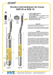
The probe can be suspended from the power supply cable, but where there is a danger that it may catch on
protruding elements it is recommended that the probe be suspended on a steel cable using the supporting
handle(not applicable to SGE-16). If the cable is to be exposed to current or turbulence, it should be installed
in a protective tube, e.g. one made from PCV.
Directly before location the probe in measured medium to take off from diaphragm seals
SGE-25S, SGE-25S.SMART, SGE-25C the securing cover.
i
The probe with an additional Teflon shield suspend on a steel cable or on a internal cable (do not catch
for teflon).
The probe in EEx-version with a cord for earthing suspend on a steel cable using the lifting handle
8.2. Electrical Connection.
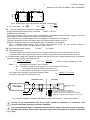
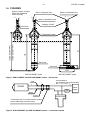
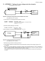
The method of making electrical connections is shown in figure 2, 3 (for EEx version in figure 3 „Appendix Ex”).
If the transmission line leads to remote premises via the open air, it is recommended that a terminal box, be
fitted, e. g. the Aplisens type PP, in order to connect the probe’s cable to the remaining section of the
transmission line. The box should have an IP65 ingress protection rating, and but should not be so airtight as
to prevent the probe’s active sensing device from “breathing” via a capillary embedded in the cable.
The opening of the capillary should not be allowed to become dirty, and water should not be allowed to enter
the capillary.
Where the transmission line is very long, it is recommended that the section leading from the end of the probe
cable be made from twisted pair cable, and it is desirable that entry points to other devices be fitted with
excess voltage protection, e. g. the Aplisens UZ-2 system.
The cable of the probe and the remaining section of the transmission line should be protected from
mechanical damage.
9. SETTINGS AND REGULATION.
9.1. Settings of SGE-25, SGE-16, SG-25C and SGE-25S probes
The SGE-25, SGE-16, SGE-25C and SGE-25S are factory set to the range stated in the order. The user does
not have access to the “zero” and “range” potentiometers. Setting may be adjusted by the manufacturer only.
9.2. Settings of SGE-25.SMART, SGE-25S.SMART probes
In SGE-25.SMART and SGE-25S.SMART probes with smart electronic, user can make e.g. set „zero” and
measurement ranges.
9.3. SGE-25.SMART, SGE-25S.SMART. Measurement ranges. Definitions.
9.3.1. The maximum range of level, while the probe can measure is called „basic range” (for specifications
of “ basic range” see 5.1.1.).
The width of the basic range is the difference between the upper and lower limits of the basic range.
The internal characteristic conversion curve for the basic range is coded in the probe’s memory.
This is the reference curve used when making any adjustments which affect the probe’s output signal.
9.3.2. When the probe is in use the term “set range “ is used.
The set range is the range whose lower end-point corresponds to an output current of 4mA and whose
end-point corresponds to a current of 20mA (or 20mA and 4mA respectively when the conversion
inverted). The set range may cover the whole of the basic range or only a part of it. The width of the set
is the difference between the upper and lower limits of the set range. The probe may be set to any
within the basic range of level values, subject the restrictions set out in the table in 5.1.1.
upper
curve
range
range
9.4. Configuration and Calibration.
9.4.1. The SGE-25.SMART and SGE-25S.SMART probes has features which enable metrological and
identification parameters to be set and altered. The configurable metrological parameters affecting the probe’s
output signal include the following:
a)
unit in which the measured level is expressed on the display
b) upper end-point of the set range
c)
lower end-point of the set range
d) time instant
e) type of characteristic curve: linear or radical