1
INTERNAL SWITCHES, JUMPERS AND ADJUSTMENTS
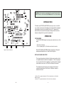
There are several internal switches, jumpers and adjustments that affect operation. These
are described below. To gain access to the switches, jumpers and adjustments,
disconnect all power and line connections. Remove two screws from the top of each side
and two screws from bottom of each side. Switch, jumper and adjustment locations are
shown in Figure 2.
Sidetone Adjustment (R145)
The sidetone adjustment is accessible either internally (refer to Figure 2) or by
removing the belt clip mounting screw (callout 5 in Figure 1).
To adjust the level of your own voice heard in the headphones, tap the Talk button once
to turn on the headset microphone. Then, use a small flat-blade screwdriver to
increase or decrease your voice level while talking into the microphone.
Mic Gain Adjustment (R156)
The Mic Gain adjustment is accessible internally on the board (R156) See Figure 2.
To adjust Mic Gain, do the following:
Using a Phillips head screw driver, turn the Mic Gain pot clockwise to increase the gain
(or counter-clockwise to decrease the gain).
D
JP3
BAL
Clear-Com Setup
D
JP2
JP1
SW1
Make the following switch and jumper changes when the belt pack is used with ClearCom equipment:
R156
UBL
R145
1.
BP-1002/2002
SW1 must be placed in the UNBAL position.
U7
SW3
SW5
R13
SW4
Figure 2. Internal Switches, Jumpers and Adjustments.
NOTE: Figure 2 shows a BP-2002 with the switches and jumpers in their factory default
positions. SW5 does not exist on the BP-1002 board
The SIDETONE adjustment is also accessible behind the screw that holds the belt clip
(callout 5 in Figure 1).
The functions of the internal switches and jumpers are described in Table 2.
NOTE: On the BP-1002, jumper JP3 must always have pins 2 and 3 shorted.
8
9