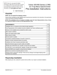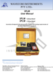
1
Ovlašteni distributer i servis
Augusta Šenoe 74
10290 Zaprešić
Tel. 01 5535 677, fax. 01 5535 678
[email protected]
System Welding Device
PF – monomatic
Rev.: 2004-001-GB
Table of contents
1
Introduction .................................................................................... 3
1.1
2
Maintenance periods ................................................................................................................... 3
Scope of application and technical data....................................... 3
2.1
2.2
2.3
2.4
Scope of application .................................................................................................................... 3
Input of welding parameters ........................................................................................................ 3
Range of fitting dimensions ......................................................................................................... 4
Technical data ............................................................................................................................. 4
3
Important safeguards ..................................................................... 5
4
Controls and Plugs......................................................................... 6
5
Power Connection .......................................................................... 7
5.1
6
Starting a welding process ............................................................ 8
6.1
6.2
7
Function menu........................................................................................................................... 12
Adjusting the display contrast.................................................................................................... 12
System configuration / Change language.................................................................................. 13
Trouble shooting .......................................................................... 14
8.1
8.2
8.3
8.4
9
Preparation .................................................................................................................................. 8
©
Welding with the FUSAMATIC -Mode ...................................................................................... 10
Other Functions............................................................................ 12
7.1
7.2
7.3
8
Generator suitability..................................................................................................................... 8
Replacing Welding Terminals ................................................................................................... 14
Adapter ...................................................................................................................................... 14
Start messages ......................................................................................................................... 14
Error messages ......................................................................................................................... 15
Conformity Declaration ................................................................ 17
Please note the safeguards in chapter 3
2
Rev.: 2004-001-GB
1 Introduction
Dear customer,
we thank you for the confidence in our product and wish you a contented work with it.
The present instructions manual includes, beside the description of the use of the devices, important
notes for your safety and the scope of application. Therefore, you should read carefully the present
instructions manual before the first use of the device. In case of failure or interruption of the workflow read
the appropriate chapter of this manual. Self-evidently we are ready to assist you at any time:
HIDROEX d.o.o.
Augusta Šenoe 74
Zaprešić
Tel. +385 1 55 35 677
Fax. +385 1 55 35 678
[email protected]
All notes and technical specification in this instructions manual were prepared with all necessary care. The
manufacturer keeps the right to make technical changes at the device, which are not directly included into
the present instructions manual.
1.1 Maintenance periods
Please note, that the bought product is a technically demanding machine for field application. In
accordance to the applicable standards like DVS 2208-1, BGV A2, ISO 12176-2 and most national and
international standards, these machines have to be subjected to a periodical maintenance. The
maintenance period is 12 month. When the machine is used quite often the maintenance should be
carried out more often.
During the maintenance the machine will be upgraded to the current technical state. Additionally you get a
3-month function guarantee for the maintained device.
The maintenance and the related checks are important for you safety and the continuous working
reliability of the control unit. Therefore the maintenance and all necessary repairs, have to be carried out
by the manufacturer or a authorised service point.
2 Scope of application and technical data
2.1 Scope of application
The electro fusion control units of type Monomatic are exclusively for the electro fusion of thermoplastic
pipes (e.g. made of PE-HD, PE80. PE100 or PP) by use of electro fusion fittings with an welding voltage
lower than 48V . The control units are conform to the standard DVS 2208-1 as well as the ISO 12176-2,
which refer to the standards applicable for the electro fusion fittings to be used.
It is not allowed to use the electro fusion controllers, to which the present instruction manual refers to, for
an application not covered by the above stated terms. The manufacturer is not liable for the use of the
machine out of the scope of application.
2.2 Input of welding parameters
The electro fusion controllers of type Monomatic provides the following means for entering the welding
parameters:
FUSAMATIC-System:
By reading out the reference resistance in the connector pins of the FUSAMATIC-Fitting the control unit
automatically takes over the welding data of the fitting.
Rev.: 2004-001-GB
3
2.3 Range of fitting dimensions
For which range of fitting dimensions a electro fusion control unit can be used depends essentially on the
power consumption to the used fittings itself. Since the power consumption of the fittings are different for
different fitting manufacturers, a general statement concerning this point is hardly to make. In case of
doubt, each single case has to be checked separately. For electro fusion control units of the type
Monomatic the following general statement can be made, with the assumption, that all welding processes
were made one after the other, i.e. that the control unit is able to cool down during the preparation time of
the next fitting:
Note: The Monomatic control unit can be used for FUSAMATIC fittings only.
Use for dimension 20-355mm without any limit.
From a diameter for 400mm and higher there must be provided longer off-times to ensure a cooling
down of the control unit (Error message “Device too hot”). Before processing fittings in this dimension
range, you have to check that the welding current of the fitting does not exceed the maximum output
current of the control unit.
All above made statements refer to an ambient temperature of 20°C.
2.4 Technical data
Technical Data – Technische Daten
Monomatic
ISO 12176-2 Class - Klassifizierung
P2 3 U S1 F A M
Input Voltage - Eingangsspannung
230V ~/AC, (185V-300V)
Input Current - Eingangsstrom
16A
Input Frequency - Eingangsfrequenz
50Hz (40-70Hz)
Output Voltage - Ausgangsspannung
40V
Output Current - Ausgangsstrom
Power Consumption - Leistungsaufnahme
60A (max.: 80A)
3200VA
Temperature Range - Arbeitstemperatur
-10°C - +50°C
Protection Class - Gerätesicherheit
IP54, Class 2
Weight incl. Cables - Gewicht inkl. Kabel
18kg
Main Supply Cable - Netzkabel
4,5 m (Euro-Plug – Euro-Stecker)
Welding Cable - Schweißkabel
5m (fixed – fest)
Welding Terminals - Anschlußkontakt
Display - Display
Dimension - Abmessungen
4,7mm (opt. 4,0mm)
4 x 20 Characters (alphanum.), background lighting
4 x 20 Zeichen (alphanumerisch), Hintergrundbeleuchtung
440mm x 380mm x 320mm
Monitoring Functions Überwachungsfunktionen
Input - Eingang
Output - Ausgang
Other - Sonstige
Error Messages - Fehlermeldung
Enclosed Parts - Lieferumfang
4
Voltage / Current / Frequency
Spannung / Strom / Frequenz
Voltage / Resistance / Contact / Short circuit / Current Monitoring
Spannung / Widerstand / Kontakt / Kurzschluß / Stromüberwachung
System / Working Temperature / Service
System / Arbeitstemperatur / Wartung
Plain Text / Acoustic Signal
Klartext im Display / Dauerwarnton
Control Box, Transport Box, Instructions Manual
Gerät, Transportbox, Bedienungsanleitung
Rev.: 2004-001-GB
Technical Data for 110V Control Units
Technical Data – Technische Daten
Monomatic
Input Voltage - Eingangsspannung
110V ~/AC, (90V-150V)
Input Current - Eingangsstrom
Input Frequency - Eingangsfrequenz
40A
50Hz (40-70Hz)
3 Important safeguards
Before turning on the welding device, please, read this operating instructions as well as
the relevant safety and processing directions carefully.
Warning! With the use of electric tools you have to note the following basic safety
direction to protect against electric shock, injury and fire.
1. Keep your working area in order !
Disorder involves a certain danger.
2. Consider the influence of environment !
Do not expose electro tools to rain. Do not use electro tools in wet or damp surroundings or in the
neighbourhood of combustible liquids or gases.
3. Protect yourself against electric shock !
Avoid body contact with grounded components (e.g. radiators, metal pipes) or live cables. Do not carry the
device, with the finger on the power switch. Pull out the plug when you do not use the tool or when
changing the adapters and attachments.
4. Keep unauthorized people and children away !
Do not allow other people touch the device or cables – keep them away from your working place.
5. Store up your device safely !
Unused machines should be kept in a dry and locked room, inaccessible for children and unauthorized
people.
6. Use permitted accessories only!
Do only use accessories, especially current sources and lengthening cables, that are stated in the
operating instructions or recommended by us. The use of attachments, that are not stated in the operating
instructions, involves a certain danger for you. Do only use permitted and marked lengthening cables
outdoors.
7. Do not expose the cables to avoidable loads !
Do not carry the machine with the cable and do not use the cable to pull out the plug. Protect the cables
against heat, oil and sharp edges.
8. Lock after your tools carefully !
Keep your device clean. Follow the servicing instructions and the instructions for changing the tools. Keep
oil and grease away from the straps.
9. Check your device for damages !
Check your tools before every use for damages and function of the protection devices and machine parts.
All parts have to be mounted in the right way. They have to fulfil all conditions for a impeccable running of
the tool. Damaged protection devices and machine parts have to be repaired or replaced by an authorized
service point.
Rev.: 2004-001-GB
5
4
Controls and Plugs
(1) DISPLAY
(2) START
(3) STOP
(4)
(5)
(6)
(7)
(4) Power Switch
(5) Welding Cable
(6) Cable Holder
(7) Power Supply Cable
6
Rev.: 2004-001-GB
5 Power Connection
The connecting conditions of EVU, the VDE-directions, the accident prevention
regulations, DIN/CEN-regulations as well as national regulations have to be considered.
Electro Fusion Control Units have to be used by operators, which are trained and authorised conform the
national and international standards and directives, only. The operator has to supervise the electro fusion
control box during the whole fusion process.
The electro fusion control unit has to be used within the following ranges:
Parameter
230V Control Units
110V Control Units
Input Voltage:
185V – 300V (AC)
90V – 150V (AC)
Input Frequency::
40Hz – 70Hz
40Hz – 70Hz
Ambient Temperature:
-10°C – +50°C
-10°C – +50°C
Max. Output Power:
3600W
3600W
Caution: 110V Control Units shall not be used at 230V power supply and vice versa.
When operating on a electric distributor or the main power supply of nominal 230V, a min. 16 Amps slow
fuse comprising a residual current-operated protective device (RCCB) should be used (110V: min.
32Amps).
Extension Cables:
To extend the power supply cable you have to follow the following rules:
Cable length
Cross Section (230V)
Cross Section (110V)
Up to 20m
3 x 1.5mm²
3 x 4mm²
20 to 50m
3 x 2.5mm²
3 x 4mm²
50-100m
3 x 4mm²
-
It is not allowed to extend the welding cable!
Important notes for the use of generators:
•
First start generator, then plug in the device.
•
No other machine or device shall be connected to the generator
•
The idle running voltage should be regulated to 240V – 260V (AC) at nominal 230V
(nominal 110V: 120V – 130V (AC)).
•
Plug out welding device before turning off the generator.
•
The usable generator power will decrease by 10% per 1000m height.
•
Check the fuel level before starting the welding process.
Rev.: 2004-001-GB
7
5.1 Generator suitability
The Electro Fusion Controllers of type Monomatic provide the following means to increase the generator
suitability:
•
Wide tolerance for input voltage and Input frequency.
•
Display of current input voltage and frequency.
•
Soft-Start for limitation of the generator load.
Despite this characteristics, the generators to be used have to fulfil the following requirements and
recommends, in order to avoid damaged of the control unit and to ensure that the internal monitoring
function of the control unit will not interrupt the welding process:
•
suitable to drive inductive loads and phase cut systems
•
no-load voltage adjustable to 240V – 260V at nominal 230V (nominal 110V: 120V – 130V (AC)).
•
output current of 18 Amps at one phase at nominal 230V
•
stable output voltage and engine speed, also at fast alternating loads
•
synchronous generators with mechanical speed control preferred
•
voltage peaks must no exceed 800V
(nominal 110V: 36Amps).
Min. required generator output power 230V, 50Hz, 1-phase
Diameter
Output Power
20-75 mm
2kW
90-160 mm
3,2kW
180-710mm
4.5kW (mechanically controlled)
5kW (electronically controlled)
For generators with insufficient control performance or voltage control it has to be selected 3-3.5 times
higher output power than the stated ones to achieve an undisturbed operation. Electronically controlled
generators tent to oscillate with the control of the welding process, which can lead to high output voltage
peaks. Please, test suitability before using that kind of generators.
Manufactures like HONDA, EISEMANN, GEKO, FISCHER, PANDA and KIRSCH provide generators
performed especially for this kind of application.
Caution: 110V Control Units shall not be used at 230V power supply and vice versa.
6 Starting a welding process
6.1 Preparation
Before starting you have to carry out the following steps in the given order:
8
1.
Check the device, cables and adapters visually. If necessary you have to replace them.
2.
Plug in Detachable welding cables.
3.
Unroll welding, power and extension cables completely.
4.
Switch of the Power Switch of the control unit.
5.
Start the generator before you plug in the control unit. Wait until the generator output
voltage has stabilized.
6.
Plug in the power cable of the control unit.
7.
Switch on the power switch.
Rev.: 2004-001-GB
Caution: 110V Control Units shall not be used at 230V power supply and vice versa.
After this procedure, the control unit signals its readiness with two bleeps. In addition the display
backlight is turned on automatically. The following display message appears:
PF-Monomatic
Version 2.04AH
25 Working hours
Line 1 and 2 show the type and version of the control unit.
Line 3 shows the total amount of working hours of the control unit.
If there occurred any error or change of the system configuration at the last weld before turning off the
device, this will be indicated by a message in the display once again. After pressing the red STOP-key you
are able to carry out a new welding process.
As long as no fitting is connected, no welding process can be started.
Connect Fusamatic
Voltage:
230 V
Frequency:
50 Hz
No contact
Line 1 prompts you to connect a fitting
Line 2 shows the input voltage. In case of generator use check that the voltage is at about 240-260V at
nominal 230V (nominal 110V: 120V – 130V (AC)).
Line 3 shows the input frequency
Line 4 indicates that no fitting in connected
Welding Terminals:
-
The contacts of the welding connector and the fitting plug must be clean – dirty or coated
contacts can lead to overheating and burn at the connectors.
-
Generally the terminals have to be protected against dirt. If there is a coating or loss of stick
force on the connectors they have to be replaced.
-
Use Adapters to connect certain fitting types. Adapters wear out with the time and have to be
checked before every use.
Note: The Monomatic control unit can be used for FUSAMATIC fittings only.
Connect the welding terminals of the control unit to the pins of the fitting. Take care on a firm and proper
fit. You have to pay attention for the right connection between the welding connectors and the fitting plugs.
The red terminal must be put on the fitting pin which is marked with the red ring. Thus the welding
device can detect the fitting type and its welding parameters.
Rev.: 2004-001-GB
9
6.2 Welding with the FUSAMATIC©-Mode
Pay attention to the installation instructions of the fitting, special instructions (ISO,
DVGW, DVS), European and national directions as well as the laying instructions!
Note: The Monomatic control unit can be used for FUSAMATIC fittings only.
As long as no fitting is connected, no welding process can be started. Connect the welding terminals of
the control unit to the pins of the fitting. Take care on a firm and proper fit. You have to pay attention for
the right connection between the welding connectors and the fitting plugs. The red terminal must be put
on the fitting pin which is marked with the red ring. Thus the welding device can detect the fitting type
©
and its welding parameters. It will switch to the FUSAMATIC -Mode automatically. This will be indicated
by the following message:
START
Nom. time: 0200s
FUSAMATIC
40V
Line 1 prompts you to confirm the shown welding parameters.
Line 2 Shows the welding time.
Line 3 shows the fitting type and welding voltage.
Line 4 shows error messages respectively.
You have to compare the shown parameters with the parameters stated on the fitting. In the case that
these deviate or if a Contact error is indicated in the lowest row of the display, a faulty or invalid reference
resistance is read. Disconnect the welding terminals from the fitting plugs. Check the connectors of the
fitting and welding cable for dirt or coating. If the fitting causes another Contact error or differing
parameters, it is defect. Replace it.
If no Contact Error occurs, you can confirm the correctness of the welding parameters by pressing the
green START-key. The following message will remind you of your duty to fix and prepare the pipes
according to the general guidelines:
Is the pipe scraped ?
If you have any doubt about the right preparation, you can break off the procedure by actuating the red
STOP-key. Otherwise confirm the proper preparation by pressing the green START-key.
The welding device starts the welding process automatically. To avoid danger for your health, do not
touch the fitting or cables during the welding process.
10
Rev.: 2004-001-GB
The display shows the actual and nominal welding time:
Act. time:
Nom. time:
FUSAMATIC
0099sec
0200sec
40V
Line 1 shows the running welding time.
Line 2 shows the target welding time
Line 3 shows the fitting type and the nominal welding voltage.
Line 4 shows error messages respectively.
The welding process will stop automatically when the actual time reaches the nominal time. This will be
indicated by two bleeps and the following message:
Act. time:
0200s
Nom. time:
0200s
FUSAMATIC 40V
- OK Line 1 shows the stop time.
Line 2 shows the target welding time.
Line 3 shows the fitting type and the nominal welding voltage.
Line 4 shows error messages respectively or the -OK- message.
Disconnect the welding connectors to go back to the start message.
Rev.: 2004-001-GB 11
7 Other Functions
7.1 Function menu
After connecting the control unit to the power supply and switching on, wait until the machine indicates it
readiness by two bleeps . Then aboard all error messages by pressing the red STOP-button.
by simultaneous pressing of the START and STOP-key the following two menu items will be shown in the
display:
>Contrast
System config.
> (Cursor)
Marks the active menu item.
START (short)
Moves the cursor upwards.
STOP (short)
Moves the cursor downwards.
START (3 sec.)
Selects the marked menu item.
STOP (3 sec.)
Cancels the function menu.
7.2 Adjusting the display contrast
By selecting the contrast function of the function menu you can adjust the display contrast to your
needs:
Contrast
240
The shown value is only given for your orientation. It can show numbers from 100 to 250. At high values
the belong to strong contrast.
START (short)
Increases the display contrast.
STOP (short)
Decrease the display contrast.
START (3 sec.)
Accepts the shown display contrast.
STOP (3 sec.)
Cancels the function.
12
Rev.: 2004-001-GB
7.3 System configuration / Change language
To show the system configuration menu, you have to select the System config. function:
Language
GB <
To change the display language press START (short).
After selecting the language function from the system configuration menu the display will show a list of
language indicators.
>GB
SE
ES
The indicators stand for: GB = English, SE = Swedish, ES = Spanish, IT = Italian, DK = Danish, PT =
Portuguese, DE = German, FR = French, PL = Polish, TR = Turkish, RO = Romanian, etc. Please note
that only 7 languages are available.
START (short)
Moves the cursor upwards.
STOP (short)
Moves the cursor downwards.
START (3 sec.)
Selects the marked language item.
STOP (3 sec.)
Cancels the language menu.
Rev.: 2004-001-GB 13
8 Trouble shooting
8.1 Replacing Welding Terminals
The welding plugs should be checked frequently. If necessary they can easily replace in no time.
1.
Switch off the device and disconnect it from the mains supply or generator!
2.
Slip off the PVC-cap over the welding terminal.
3.
Hold the front part of the brass contact with a pipe wrench and screw the welding terminal with a 8mm-wrench
out of the brass contact.
4.
The red welding cable has to be equipped by a welding terminal with detection tip! You have to use welding
terminals that are delivered by PF only!
5.
Screw the new welding terminal tight into the brass contact and slip the PVC-cap over the welding terminal. Pay
attention, that the PVC-cap is slipped over so far, that the welding terminal is left blank for about 15mm.
1_0200_001
1_0200_003
2_0200_003
2_0200_004
1_0410_004
1_0410_003
Welding Terminal 4.7mm, standard
Welding Terminal 4.0mm, standard
Welding Terminal 4.7mm, Fusamatic (with detection tip)
Welding Terminal 4.0mm, Fusamatic (with detection tip)
PVC-Cap, red
PVC-Cap, black
8.2 Adapter
For different fitting types different adapters are needed. In the following table you will find a selection of
available adapters:
1_0200_005
1_0200_006
1_0200_007
FUSAMATIC-Adapter 4.7/4.7
FUSAMATIC-Adapter 4.7/4.0
FUSAMATIC-Adapter 4.0/4.7
8.3 Start messages
After switching on the device the following message appears on the display:
PF-Monomatic
Version 2.04AH
25 Working hours
Row 1 and 2 show the type and firmware revision of the control box.
Row 3 counts the total amount of working hours (summed up fusion times).
After ten seconds the above shown display will disappear.
In the following there could be shown system messages like error messages of previous welding
cycles or service notes, which can be aborted by pressing the red STOP-key.
14
Rev.: 2004-001-GB
8.4 Error messages
Error messages will be indicated by a bleep. A permanent bleep can be interrupted by pressing the red
STOP-key.
Error
Cause
Reaction
Clock error
Internal clock does not work properly.
Set clock.
Maybe the battery has to be changed.
Code error
Faulty input.
Move the reading pen with a constant
velocity over the barcode.
Barcode defect or error of code
structure.
©
Contact error
Invalid FUSAMATIC -detectionresistor.
Clean contacts.
Replace fitting if necessary.
Current high
Output current is more than 15%
higher than the starting current.
Shortcut of fitting coil or welding cable.
Current low
Interrupt of the welding current.
Welding is faulty!
Current drops down about
15-20% for at least 3s.
Welding is faulty!
Device too hot
Temperature of transformer is too
high
Let the device cool down for about 45
min.
Emergency cut-out
Welding was interrupted by pressing
the STOP-key.
Welding is faulty!
Frequency error
Input frequency out of working range
(40-70Hz).
Check Generator.
Input voltage high
Input voltage >300V at 230V nom.
Input voltage >150V at 110V nom.
Adjust generator voltage to 240V-260V.
Adjust generator voltage to 120V-130V.
Input voltage low
Input voltage < 190V at 230V nom.
Input voltage < 90V at 110V nom.
Unwind the power supply cable.
Use power supply cable with the right
diameter.
Adjust Generator voltage.
Interturn shortc.
The current rises more than 15%
during the welding. Shortcut of the
fitting coil.
Welding is faulty!
Memory overflow
Report memory is full up.
Print reports or deactivate the memory
control option.
No contact
No complete electrical contact with
the fitting.
Check connection to the fitting.
Fitting coil or welding cable is defect.
Use an other Fitting.
Change welding cable.
Rev.: 2004-001-GB 15
Error
Cause
Reaction
Output volt. Error
The output voltage deviates from the
rated voltage.
Check the generator.
Revolutions fluctuate or power too
weak.
Power failure
Last welding was interrupted by a
break of the power supply.
Last welding is faulty! Prepare pipe
again and use a new Fitting!
Resistor error
Fitting resistance is out of the valid
working range.
Clean the contacts.
Use an other fitting.
Fitting resistance out of the valid
range given by barcode.
Clean the contacts
Use an other fitting.
Service
The recommended service interval of
12 months or 200 working hours is
exceeded.
The device has to be checked by an
authorized service point.
The device is still usable, but the
manufacturer does not accept any
liability for the device until it is checked
up.
System Error
Danger! Self test found an error in the Disconnect power supply immediately.
system.
Do not connect the device to the power
supply any more. Send it to the next
service point.
Temp. Meas. Error
Temperature measurement is faulty.
Temperature error
Surrounding temperature out of
working range (-10-+50°C).
16
Plug in the removable welding cable.
Switch device off and on.
Welding cable or sensor defect.
Rev.: 2004-001-GB
9 Conformity Declaration
Rev.: 2004-001-GB 17
18
Rev.: 2004-001-GB
Rev.: 2004-001-GB 19