1
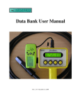
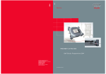
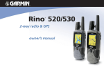
INSPIRE OSD
FREQUENTLY ASKED QUESTIONS
Q:
A:
Q:
A:
Q:
A:
I do not have any experience with soldering or electronics in general. Will I be able to
connect the OSD board to my wireless camera equipment?
Your video equipment will need to be wired to the OSD board. Although this is a simple
task to someone that has some electronics experience, it will probably be a frustrating
effort for beginners. All of our documentation is online, so you can see for yourself if your
skills are up to the task. If not, then please arrange for hands-on help from someone with
electronics experience.
I’m not using the RSSI and external voltage inputs. Why does the display show a voltage
for them? That is to say, why don’t they show 0VDC?
With nothing connected to the inputs they will display random voltages. If you are not
using these fields then it would be best to turn them off. Or better yet, put them to use!
I understand that the RSSI input accepts a 0VDC to 5VDC voltage range. However, the
voltage I want to use is higher than that. Is there a solution?
It is important that the RSSI input voltage does not exceed 5.0VDC or damage may
occur. For higher voltages a voltage attenuator (divider) must be created using resistors.
A typical circuit is shown below. The component values will depend on your application.
For example, to divide the signal input voltage by ten, R1 should be 9K and R2 should be
1K. Capacitor C1 is typically .1uF, but its value will depend on your requirements.
Figure 2, Attenuator Example
Q:
A:
The tachometer does not seem to work. Also, when I’m in the configuration screen that
shows the Magnet Count value, I never see the star (i) character. I understand that it is
present when the magnet is near the sensor. What is going on?
The magnets should be within 1/16" of the sensor for reliable operation. More important,
the tach sensor is sensitive to only one pole of the magnet. My advice is to flip the
magnet over to the other side (an opposite pole) and try again.
INSPIRE FAQ ©2006-2007
Page 1
Nov-07-2007
Q:
A:
How many magnets should I use with the tachometer sensor?
Most applications would use two magnets placed 180 degrees apart. By the way, the
resolution of the tachometer is dependent on the number of magnets that are sensed per
revolution. The resolution is summarized below:
Tach Resolution
1 Magnets: 60 RPM
2 Magnets: 30 RPM
3 Magnets: 20 RPM
4 Magnets: 15 RPM
5 Magnets: 12 RPM
6 Magnets: 10 RPM
Note: Magnets should be evenly spaced. Above 9999 RPM the displayed resolution is
formatted to 100RPM resolution regardless of magnet count.
Q:
A:
My R/C ground range test does not pass when the video gear is used. What should I do?
It is important that your R/C ground range test meet or exceed the manufacturer’s
recommendations. If your ground range test is not acceptable then the problem must be
resolved before using the R/C system. Here are some things to try:
1.
Never power the video system with the R/C system’s battery. Use a dedicated
pack.
2.
Keep the video equipment far away from the R/C receiver and all wiring.
3.
Keep the GPS cable/antenna far from R/C antenna.
4.
Change the routing of your video wiring.
5.
Keep all wiring as short as possible.
6.
If necessary, disconnect Inspire from the R/C receiver.
Q:
A:
I’m using the micro-GPS module and want a longer cable for it. Do you offer one?
Not at this time. However, if you are skilled at soldering, you can extend the cable up to
eight inches. The longer wires may introduce more EMI/RFI; do not allow your extended
cable to be routed near your R/C system.
Q:
I’m confused about the fields that show waypoint bearing and distance, as well as the
return to home direction arrows. What exactly is a waypoint and what do I need to see all
this data?
A waypoint is a specific geographical location. It is identified by its longitude and latitude
position. Some GPS receivers allow the user to store one or more waypoints and then
use the GPS to direct them to these locations. In addition, the return to home arrow is
nothing more than a waypoint to your starting location. To use the waypoint data, Inspire
is designed to interface with the popular Garmin Geko 201 GPS receiver. This GPS
system allows for easy entry of the waypoint information, including complex routes with
several waypoint locations. During use, the Geko sends the real time waypoint status to
Inspire, which it then displays to you.
A:
In the example shown in Figure 2, the data outlined in blue says
that you must turn 32 degrees to the right in order to head
toward arriving waypoint number 08. The waypoint is currently
0.03 miles away.
Figure 3, Waypoints
INSPIRE FAQ ©2006-2007
Page 2
Nov-07-2007
Q:
A:
The micro-GPS module’s data seems to be unstable when it is sitting still on a table. Is it
defective?
The GPS receiver is fine. When the GPS is stationary (static operation) the data will
often change on its own due to the satellite signal processing. For those applications that
are bothered by this, there is a setting in the GPS menu that can be used to reduce the
bouncing data. Please see “Motion Filter” on Page 13 of the User Manual.
Q:
A:
I don’t get reliable GPS data while testing the system in my workshop. What is wrong?
GPS receivers are designed for outdoor use. For reliable operation you’ll need to move
outside to an area that has clear view of the sky. Please allow several minutes for the
receiver to establish a GPS signal lock with the heavenly satellites.
Q:
Even though I reset the AGL altitude, it does not always return to zero when I go back
the exact same location. Sometimes it is off by nearly 50 feet!
The accuracy of GPS altitude is typically fifteen meters. It can be better or worse,
depending on the geographical location and satellite fix. If WAAS signals are available in
your GPS area, and you have the WAAS/SBAS feature enabled in the setup menus
(GPS Hardware, Page 4), then you have the best accuracy possible.
A:
Q:
A:
Q:
A:
Q:
A:
What is the pin-out of Inspire’s 4-pin RS-232
connector? What are the RS-232 voltages?
The pin-out is shown in Figure 3. The voltage
levels are standard RS-232 (~±12VDC).
The current sensor’s cables seem very short.
Why aren’t they much longer so that they can
reach all the way to my battery pack?
The provided current sensor wires are
deliberately kept short to encourage the end
user to choose the best wire gauge for their
application. Please add your preferred
connector (quality made 4.5mm bullet is typical)
to the provided wires and then adapt to the wire Figure 4, External RS-232 Connector
size and length that is needed in your
installation.
I would like to measure slightly more than 75 Amps during the brief periods my
propulsion motor is under heavy load. Is this possible?
The stock setup is rated for 75 Amps DC. However, the current sensor IC can accurately
measure up to ±100 Amps DC. For safety, the stock heavy gauge wire leads will need to
be replaced with a much heavier gauge. Please keep in mind that high currents require
very high quality connections to ensure safe and reliable operation.
INSPIRE FAQ ©2006-2007
Page 3
Nov-07-2007