1
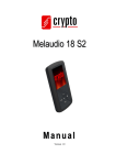
TT OBDii Tracking Device with DTC User Manual TT OBDii TRACKIING DEVICE INTRODUCTION The TT OBDii tracking device is a plug and play dedicated tracking device which can connect directly into a vehicles OBDII diagnostic port. The TT OBDii is designed for ease of installation and combines state of the art gsm and gps engines with fully internal antennae, on board processors and movement sensors and integrated software ensures exceptional power management to lower battery drain. The TT OBDii is fitted with the highest quality GPS uBlox modules the TT OBDii is able to use A‐GPS (Assist GPS) technology to ensure greater accuracy and faster acquisition time. The TT OBDii has full remote immobilize functionality if the device is removed, to ensure added vehicle security. The TT OBDii was developed in co-operation with leading electronic assemblers to ensure a highly robust, hassle free product of the highest quality, consistent with Tracktech’s complete product range. S P ECIFICATIONS P h ys ic a l S p e c ific a tio n S ize 55 x 50 x 25 mm We ig h t 80 g IP Ra tin g IP62 Re c h a rg e a b le Ba tte ry 7.4V 180mAh Lithium ION Sleep mode < 20uA P o we r P o we r Co n s u m p tio n Power Save mode Max. Performance MCU < 5mA < 300mA MCU TI MSP430 12KB RAM, 256KB Flash An te n n a Internal Mo d e m uBlox LEON 100 Fre q u e n c y Quad band 850/900/1800/1900MHz GP RS Class 10 (4 downlink, 2 uplink, max. 5) Mobile Station Class B GS M Ap p ro va ls AT&T, R&TTE, CE, GCF, FCC, PTCRB, Anatel, IC, China SRRC, etc S IM c a rd 3.3V SIM 100 to 500meters(Urban) LBS Lo c a tio n Ac c u ra c y 0.5 to 30kilometers(Suburb) An te n n a Internal Re c e ive r uBlox NEO 6M (GPS, & Sbase) engine Ch a n n e ls 50 Parallel Channels S e n s itivity ‐162dBm Na vig a tio n u p d a te 1sec GP S Cold Starts: 27s Ac q u is itio n Aided Starts: <1s Hot Starts: <1s 2.5 to 10meters (Strong Signals) Lo c a tio n Ac c u ra c y 500 meters (Weak Signals) Sens or 3D G‐Fo rc e S e n s o r Onboard Me m o ry Fla s h 10,000 Locations Op e ra tin g Te m p e ra tu re ‐40 to +70 S to rin g Te m p e ra tu re ‐40 to +85 Hu m id ity 95% En viro n m e n ta l Co n d itio n s Fe a tu re s Real Time Location Real time vehicle diagnostic Diagnostic trouble codes J1962 OBDii plug interface Low power consumption 3D G-Force sensor Fuel consumption RPM and engine temperature Mobile Map Location Latitude and Longitude Location GSM Base Station Location(LBS Technology) Convenient GSM Mobile Control Easy‐to‐use SMS Communication Mode Internal Movement Sensor for better power management Internal backup battery for Device disconnection notification Internal memory for the data buffer Monitor driver behavior, hard braking, acceleration and harsh turning Anti theft immobilize if removed OBDii Protocols: SAE J1850, ISO 9141-2, ISO 14230-4, ISO 15765-4 Qu ic k In s ta ll In s tru c tio n s P lu g a n d P la y The TT OBDii is supplied f u l l y c o n f i g ur e d r ea d y f o r s i m pl e p l u g an d p l a y o p e r at i on . I t i s a l s o s u p pl i e d with a USB cable for further configuration if required. For further information on device configuration contact our customer service department at email: [email protected] S IM c a rd Tracktech devices come fitted with one of Tracktech’s Intelligent Multiple Network Roaming sims which allow our devices to operate worldwide. If you would like more information on these sims don’t hesitate to let us know. If your device was bought without an IMNR sim the user must arrange a SIM card with valid data plan. Before inserting the SIM card it should be tested with your own mobile to ensure the sim is operating and is data enabled. Insert the SIM card in your own mobile and try to send out SMS and receive SMS if it works fine then try to connect to internet by opening any website in mobile browser. If this works then you can insert into the TT OBDii by removing the black cover from the TT OBDii SIM card jack hole. After removing the black cover you can insert the SIM card in the jack. Press the SIM card inside the SIM card jack completely. Lo c a tin g OBDII P o rt Normally t h e ODBII port is available in all the vehicles manufactured after 2000. This port is located under the dash near the driving side of the vehicle. Normally this port is covered with a cover. Co n n e c tin g TT OBDii Remove the cover on the OBDII port and connect the TT OBDii to the same port by inserting the device into the plug slot LED Fla s h e s & Re le va n t De vic e S ta tu s There is an external LED light to reflect t h e device status of the TT OBDii. In order to check t h e device status through this LED light flashes, the LED is located right next to the USB port. When t h e device is at work, t h e LED will flash at 8‐ sec cycle constantly to show related GSM and GPS status in each cycle. In each flash cycle when device is at work, LED will flash to indicate GSM status first then GPS status (there is an interval between them). To check the statuses, please count the LED light flashes then compare it to the chart below: S ta tu s LED Fla s h e s Device Power on LED ON <1sec GSM module ON but unregistered 1 flash at the beginning of each flash cycle GSM module ON and registered 2 flashed at the beginning of each flash cycle GSM module OFF No flash at the beginning of each flash cycle GSM module on and registered 3 flash then GPRS connection GSM module on and registered 4 flash then TCP connection GPS module ON but haven’t located 1 flash after interval (behind GSM status flash) in each flash cycle GPS module ON and located 2 flashes after interval (behind GSM status flash) in each flash cycle GPS module OFF No flash after interval (behind GSM status flash) in each flash cycle The TT OBDii also uses the LED flashes to indicate relevant error if any of the following situations happens:Device Error, SIM card no balance, GSM network cannot register. When there is any error above, LED lig h t will ON 1s e c th e n fla s h q u ic kly, which helps trouble shoot errors; t h e user can count LED quick flashes then compare it to below chart: Erro r De ta ils GSM module Communication Error LED Fla s h e s S o lu tio n s 1 flash Power OFF then check GSM module power supply and communication 2 flashes Power OFF then check whether SIM installation is good and PIN is disabled 3 flashes To check whether SIM card is overdue and/or device in an area there is no GSM signal GPS module Error 4 flashes Power OFF then check GPS module power supply and communication SMS Sending Error 5 flashes To check whether there is SIM card SMS center setting error and/or Can’t use GPRS 6 flashes SIM card is overdue To check whether the APN is correct and SIM has GPRS function or not TCP connection Error 7 flashes Unknown Error 8 flashes SIM card Error Cannot register at GSM network To check if the server is normal Power OFF then Power ON, if there is still the error, please contacts us.