1
TABLE OF CONTENTS
1. Device Introduction
1.1 Physical Appearance
1.2 Specification
1.3 Features
2. Quick Install Instructions
2.1 Open device
2.2 Insert SIM card
2.3 Power on
2.4 Configuration
2.5 Location OBDII Port
2.4 Set User No.
2.5 Modify Password
2.6 Set Work Mode
3. Commands for Device Setting
3.1 Command Table
3.1.1 Set User No.
3.1.2 Modify User Password
3.1.3 Set Upload Mode, interval and type
3.1.4 Clear Alarm
3.1.5 Location Poll
3.1.6 Set Message Center Number
3.1.7 Set APN
3.1.8 Set Voice Monitoring Number
3.1.9 Enable/Disable Over speed alarm
3.1.10 Enable/Disable Over Speed Alarm Parameter
3.1.11 Enable/Disable SMS when movement trigger
3.1.12 Set Time Zone
3.1.13 Immobilizer Output
3.2 Combine Command
3.3 Commands Wait
3.4 Alarms
3.5 Default Parameters
4. Structures of SMS from Device
4.1 Normal Location SMS Format (G Mode)
4.2 Hyperlink SMS Format (W Mode)
4.3 Error Command Alert..
4.4 Password Modification Successful Confirmation
4.5 User No. Setting Successful Confirmation
5. LED Flashes & Relevant Device Status
6. Appendix
6.1 Characters for Commands
02
04
05
06
07
08
08
09
10
11
12
13
13
13
13
13
13
14
14
14
14
14
14
15
15
15
16
16
18
19
19
20
20
20
21
23
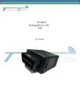
1.DEVICE INTRODUCTION
G797, which uses GSM and SMS together with GPS to locate your belongings, is a
new model tracking device designed by Gosafe Company Limited. With connect &
Go concept, G797 can connect with OBDII diagnostic port and can get necessary
power from the same port.
Inside G797, there are GSM modem, GPS receiver, control PCBA, microprocessor,
power circuit, and so on. Before starting G797 installation, please one SIM card
which works on GSM based network that is offered by GSM mobile operating
agency and can work with GPRS.
G797 is easy to install device and even nonprofessionals can install this device. You
only need to get the valid data SIM Card. Insert the SIM card in G797 and connect
the device to OBDII port in the vehicle. The system have internal movement sensor
which controls the power management of the device.
G797 is equipped with highest available GPS uBlox modules and able to use A‐GPS
(Assist GPS) technology to give help connecting the device with GPS faster with
more accuracy.
1
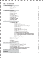
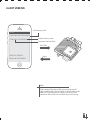
1.1 PHYSICAL APPEARANCE
Device and Components
Device opening to insert SIM card
GPS
Front Cover
Back Cover
MIC
USB Port
2
Accsessories
RF Wireless Relay
RF Tag
USB Configuration cable
Front View
USB Port
Wireless Module LED
GPS/GSM LED
3
1.2 SPECIFICATIONS
Physical Specification
Size
Weight
IP Rating
Power
55 x 50 x 25 mm
80 g
IP62
Rechargeable Battery Connector: J1962
Power Consumption 7.4V 180mAh Lithium ION
Sleep Mode 500uA
Active 70mA
MCU
MCU
GSM
TI MSP430 12KB RAM, 256KB Flash
Antenna
Modem
Frequency
GPRS
Approvals
SIM card
LBS Location Accuracy
Internal
uBlox LEON G100
Quad band 850/900/1800/1900MHz
Class 10 (4 downlink, 2 uplink, max. 5)Mobile Station Class B
AT&T, R&TTE, CE, GCF, FCC, PTCRB,Anatel, IC, China SRRC, etc
3.3V SIM
100 to 500meters(Urban)
0.5 to 30kilometers(Suburb)
GPS
Antenna
Receiver
Channels
Sensitivity
Navigation update
Acquisition
Location Accuracy
Internal
uBlox NEO 6M (GPS, & Sbase) engine
50 Parallel Channels
‐162dBm
1sec
Cold Starts: 27s
Aided Starts: <1s
Hot Starts: <1s
2.5 to 10meters (Strong Signals)
500 meters (Weak Signals)
4
Sensor
3D G-Force Sensor
Onboard
Memory
Flash
10,000 Locations
Environmental Conditions
Operating Temperature
Storing Temperature
Humidity
-40°C to +70°C
-40°C to +85°C
95%
1.3 FEATURES
Real Time Location
Mobile Map Location
Latitude and Longitude Location
GSM Base Station Location(LBS Technology)
Convenient GSM Mobile Control
Easy-to-use SMS Communication Mode
Internal Movement Sensor for better power management
Internal backup battery for Device disconnection notification
Internal memory for the data buffer
5
2.QUICK INSTALL INSTRUCTIONS
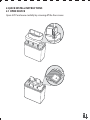
2.1 OPEN DEVICE
Open G797 enclosure carefully by screwing off the four screws.
6
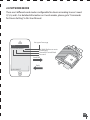
2.2 INSERT SIM CARD
Insert SIM card into the SIM card jacket correctly according to the below picture.
Press SIM card inside the SIM card jack completely.
Note
Please do activate the SIM card, disable its PIN
code function, and make sure SIM card has
enough balance before operating the device.
Each time before taking SIM card out of or
inserting SIM card into the device, device power
supply remove the device from the OBDII
connector, or it would damage device and/or
your SIM card.
7
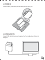
2.3 POWER ON
Connect battery to the device, like the below picture shows you:
2.4 CONFIGURATION
Connect USB cable to device and computer. Use the configuration software to
configure.
8
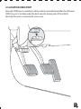
2.5 LOCATION OBDII PORT
Normally ODBII port is available in all the vehicles manufactured after the 1996 and
2000. This port is located under the dash near the driving side of the vehicle.
Normally this port is covered with some cover.
9
2.6 SET USER NO.
with country code
Message
1234,UNO;+8613912345678
1234,UNO;13912345678
without country code
Command Control Word
Send SMS
UNO:13912345678
Reply
UNO:+8613912345678
Note
After receipt of the above SMS command, device will
reply a confirmation SMS and work at default work mode:
30M;G;W To protect device, if there is any error in this
command, device will not send back any error warning.
10
2.7 MODIFY PASSWORD
To modify factory password at the first usage is strongly suggested..
New Password
Message
1234,UPW;5678
Command Control Word
Factory Password
Send SMS
Reply
UPW: 5678
Note
Please memorize your New Password and wait for
confirmation SMS for password modification from device.
Only if this command is sent by user No., the system can
process this command.
11
2.8 SET WORK MODE
There are 4 different work modes configurable for device according to user’s need:
O, S, G, and L. For detailed information on 4 work modes, please go to “Commands
for Device Setting” in this User Manual.
the type of message
Message
1234,UUM;30M;G;T
the Work Mode user wants
to configure
Command Control Word
Password
Send SMS
Reply
UUM: 30M;G;T
12
3. COMMANDS FOR DEVICE SETTING
All the commands for device setting in this User Manual are in the same format:
3.1 COMMAND TABLE
The user command is shown in the below table. The whole command format is
"PSW,CMDXX;Para".
Table only show the second part "CMDXX;Para" in the column of command format.
UNO
1) 1234,UNO;1391234
5678
2) 1234,UNO;+861391
2345678
Remarks
0~20 bits, default is empty
1) UNO:139123456
1) set national number
78
2) UNO:+86139123 2) set international number,
"86" is country number
45678
UPW
UPW;1234
UPW:1234
Sr. Description Ctrl Word Command
3.1.1 Setting user
phone
number
3.1.2 Setting user
password
Reply
3.1.3 Setting users UUM
UUM;30M;G;T
UUM: 30M;G;T
3.1.4 User alarm
UAC
UAC
to upload
mode
cleared
UAC
3.1.5 Requests for
location
PRQ
information
PRQ
PRQ
Four bits,range:0000~9999
30M:upload interval, M can be
(30~900S),(15~59M), (1~240H)
Default:30m;G;W
G: upload mode, it can be:
"O"/close uploading
"G"/upload GPS data by
interval set, when there is no
GPS, data uploading based on
base station information
"S"/Always upload with LBS
location
T: data format, it can be:
T = Text Format
W = Hyper link Format
Usage: send command to device,
the device will upload
information, Information format
is the same as upload data by
interval, and this function can
also be done by calling to the
device and hang up after first
ring.
13
Sr. Description Ctrl Word Command
3.1.6 Setting the
SMS
center
number
3.1.7 Set APN
3.1.8 Monitor
SCN
Reply
Remarks
Total is 20 bits"86" is national
code, must have. Leave factory
set: empty Default: usually, no
need to set SMS center number,
SCN:+8613800200
when user use SIM card, device
SCN;+8613800200500
500
will record SMS center number
automatically ,when change SIM
card the old number will be
delete and record new one
APN
APN: APN; user
APN; APN; user name; name;
password
password
APN;APN
APN:APN
Parameter range "APN": 1~30
characters "user name": 0~30
characters "password": 0~30
characters The second command
way "APN; APN”Means only set
APN. Device comes with of some
APN list of some mobile service
providers for some country. when
the APN information is included
for the SIM card used, no need to
configure, if APN is wrong, GPRS
connection will be wrong
VOM
VOM:13912345678
VOM;13912345678
or
or
VOM:+8613912345
VOM;+861391234567
678
8
“86”is country code
The number can’t be empty
Usage: send command, the
device will call back, open
microphone, user start
monitor
SPO
SPO;0
SPO:0
0: close
1: open
Default: SPO;1
SOP; 100;120
SOP:100;120
100: prompt
120: alarm
Default: SPO;80;100
MOT;0
MOT:0
0:Close, shielding sensor
related function IS cancelled,
relevant information don't send.
1:open ,can Use related
functions of movement sensor
3.1.9 Enable/disa-
ble over
Speed
3.1.10 Speeding
alarm
SOP
parameters
3.1.11 Motion
sensor
enable and MOT
disable
14
Sr. Description Ctrl Word Command
3.1.12 Time zone
setting
3.1.13 Immobilizer
Output
TZN
IMM
TZN;8:00
IMM;0
Reply
Remarks
TZN:8:00
Set local time zone parameter
from ‐12:00 to 12:00, Negative
represent western time zone,
positive represent east eastern
time zone
Default : 0 : 00
IMM:0
"0" : close
"1”: open device send power
cut command or the device is
disconnection, cut power of
vehicle.
3.2 COMBINED COMMAND
To save time and SMS resource on configuration, user can apply combine
command, in which there is more than one command, to operate configuration.
The combine command would begin with user password, which is followed by
commands (commands order is flexible). Format is as follow:
Pw
,
Command
word
;
Parameter
First command
;
Parameter
,
Command
word
;
Parameter
Second Command
If there is duplication of the same command in the same combine command, just
the last piece of command would be processed; if there is error in the command,
the command with error would be discarded, and device would only confirm
setting of correct commands with no error warning. If all the commands are error,
an alarm will be sent. All setting commands, except user No. setting command
under the condition of the user number has never been changed, can be set by
combine command.
Example:1234,UUM;30M;G;T,UPW;1234
15
3.3 COMMANDS WAIT
In the event that if commands come from user when device is in sleep mode then
the device couldn’t process commands, however at each wakeup, device will wait
one minute to receive those commands and take precedence to process them then
response one confirmation message; after 1 min, device would receive and process
real‐time commands and will reply accordingly.
3.4 ALARMS
The device sends alarm immediately when it triggers. The message received is as
follows when device is in alarm.
G797 V0.12
GPS 6/77
UTC 11‐05‐14 05:33:47
N23.164479
E113.428606
SPD:0km/h 0
Alarm: Power Off
LIST OF ALARMS
Description
SMS Received
Power Off
G797 V0.12
GPS 6/77
UTC 11‐05‐14 05:33:47
N23.164479
E113.428606
SPD:0km/h 0
Alarm: Power Off
Over Speed
G797 V0.12
GPS 6/77
UTC 11‐05‐14 05:33:47
N23.164479
E113.428606
SPD:0km/h 0
Alarm: Over Speed
16
Description
SMS Received
Moving (When the vehicle I
stopped and the movement
sensor is enable, the device sends
move alarm on the trigger
of movement sensor)
G797 V0.12
GPS 6/77
UTC 11‐05‐14 05:33:47
N23.164479
E113.428606
SPD:0km/h 0
Alarm: Moving
Geo‐Fence (Future use the
current version firmware don’t
support it)
G797 V0.12
GPS 6/77
UTC 11‐05‐14 05:33:47
N23.164479
E113.428606
SPD:0km/h 0
Alarm: Geo‐Fence
Anti-Jamming (This alarm
appear if the anti-jamming
feature is enable and the
someone use GSM jammer
near the device)
G797 V0.12
GPS 6/77
UTC 11‐05‐14 05:33:47
N23.164479
E113.428606
SPD:0km/h 0
Alarm: Anti‐Jamming
Note
The user can use the UAC command
to clear user based alarm.
17
3.5 DEFAULT PARAMETERS
Device is set with the following default parameters. When device powers up first
time it will use the following parameters to connect and wait for user commands or
server commands.
Description
Parameter
User number
SMS center number
PIN code of SIM
APN list
User password
User upload mode
Manager phone number
Manager upload mode
Server IP or domain name
TCP port
UDP port
TCP channel upload mode (mode 0)
UDP channel upload mode (mode 0)
Package number of per TCP upload
Package number of per UDP upload
percentage of data buffer per TPC upload
percentage of data buffer per UDP upload
Over speed
Enable/ disable over speed alarm
Enable/disable vibration sensor
Enable/disable phone roaming status test
Enable/disable anti-jamming
Time zone
Vibration sensor parameter
Anti-jamming parameter
Baud rate of extend serial port
Transmit mode of extend serial port
USB port mode
Supper link (0) GPS Link
(EMPTY)
(EMPTY)
1234
APN list of China only
1234
30M;G;W
(empty)
30M;G;T
domain name (empty) IP (114.142.154.28)
3032
3032
60S;G;B
60S;G;B
1
1
50
50
80;100
Disable
Disable
Enable
Disable
0:00
10;10;30
30;20
9600
Common mode
Common mode
http://maps.google.com/staticmap?zoom=14&size=
300x300&markers=%n,%e&sensor=false
(empty)
(empty)
(empty)
0;0
0;0
Supper link (1) (LBS Link)
Phone list of SMS forwarding
Hot line list
Time for talking
SMS number counter
18
4. STRUCTURES OF SMS FROM DEVICE
4.1NORMAL LOCATION SMS FORMAT (G MODE)
(Located Successful)
Gosafe G797 V0.10
GPS 3/56
LTM08:00 11‐24‐10 02:54
N23 9.8329
E113 25.7149
Speed: 1km/h 39
TMP=25.6C
PWR=12.5
Device Name and Version
Satellites Connected &Time used for Location (secs)
Specific time zone and Location time based on specific time zone
Latitude in degree‐minute format
Longitude in degree-minute format
Device speed and Move Direction
Temperature
Power
(Located Unsuccessful)
Gosafe G797 V1.05
MCC=460
MNC=1
LAC=517A
CID=1FB1
TMP=25.6C
PWR=12.5V
Device Name and Version
Mobile Country Code
Mobile Network Code
Location Area Code
Cell Identity
Temperature
Power
4.2 HYPERLINK SMS FORMAT (W MODE)
(Located Successful)Google link
Gosafe G797 V0.10
http://maps.google.com/static
map?zoom=14&size=150x150
&markers=39.9493,116.3875&
sensor=false
TMP=25.6C
PWR=12.5
Device Name and Version
Google Map Link
Temperature
Power
(Located Successful)Yandex link
Gosafe G797 V0.10
http://m.maps.yandex.ru/?ll=1
16.3875,39.949328&pt=116.38
75,39.949328&z=12
TMP=25.6C
PWR=12.5V
Device Name and Version
Yandex Link
Temperature
Power
19
(Located Unsuccessful
Gosafe G797 V0.10
MCC=460
MNC=1
LAC=517A
CID=1FB1
TMP=25.6C
PWR=12.5V
Device Name and Version
Mobile Country Code
Mobile Network Code
Location Area Code
Cell Identity
Temperature
Power
4.3 ERROR COMMAND ALERT
Gosafe G797 V0.10
Error command!
4.4 PASSWORD MODIFICATION SUCCESSFUL CONFIRMATION
Gosafe G797 V0.10
UPW:5678
4.5 USER NO. SETTING SUCCESSFUL CONFIRMATION
Gosafe G797 V0.10
UNO:+8613912345678
20
5. LED FLASHES & RELEVANT DEVICE STATUS
There is an external LED light to reflect device status in G797. In order to check
device status through this LED light flashes, LED is located right next to the USB
port. When device is at work, LED will flash at 8‐sec cycle constantly to show related
GSM and GPS status in each cycle.
In each flash cycle when device is at work, LED will flash to indicate GSM status first
then GPS status (there is an interval between them). To check the statuses, please
count the LED light flashes then compare it to the chart below:
Status
LED Flashes
Device Power on
LED ON <1sec
GSM module ON but unregistered
1 flash at the beginning of each flash cycle
GSM module ON and registered
2 flashed at the beginning of each flash cycle
GSM module OFF
No flash at the beginning of each flash cycle
GSM module on and registered
3 flash then GPRS connection
GSM module on and registered
4 flash then TCP connection
GPS module ON but haven’t located
1 flash after interval (behind GSM status flash) in
each flash cycle
2 flashes after interval (behind GSM status flash) in
each flash cycle
No flash after interval (behind GSM status flash) in
each flash cycle
GPS module ON and located
GPS module OFF
Device also uses LED flashes to indicate relevant error if any of the following
situations happens: Device Error, SIM card no balance, GSM network cannot register.
When there is any error as mentioned above, LED light will ON for 1sec then flash
quickly, which helps trouble shoot errors; user can count LED quick flashes then
compare it to below chart:
21
Error Details
LED Flashes
Solutions
GSM module Communication
Error
1 flash
Power OFF then check GSM module power
supply and communication
SIM card Error
2 flashes
Power OFF then check whether SIM
installation is good and PIN is disabled
Cannot register at GSM
network
3 flashes
To check whether SIM card is overdue and/
or device in an area there is no GSM signal
GPS module Error
4 flashes
Power OFF then check GPS module power
supply and communication
To check whether there is SIM card SMS
SMS Sending Error
5 flashes
Can't use GPRS
6 flashes
To check whether there is SIM card SMS
center setting error and/orSIM card is
overdue
To check whether the APN is correct and
SIM has GPRS function or not
TCP connection Error
7 flashes
To check if the server is normal
Unknown Error
8 flashes
Power OFF then Power ON, if there is still
the error, please contacts us.
22
6. APPENDIX
6.1 CHARACTERS FOR COMMANDS
0
1
2
3
4
5
6
7
8
A
b
c
d
e
f
g
h
i
j
K
l
m
n
o
p
q
r
s
t
U
v
w
x
y
z
A
B
C
D
E
F
G
H
I
J
K
L
M
N
O
P
Q
R
S
T
U
V
W
X
Y
Z
!
“
#
%
&
‘
*
+
,
-
.
/
:
>
?
@
$
Sp
_
^
[
~
]
|
9
(
)
;
<
=
{
}
\
23
www.gosafesystem.com