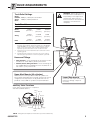
1
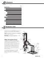
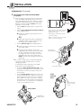
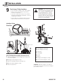
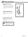
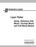
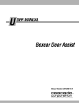
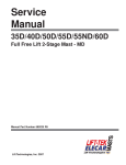
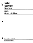
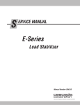
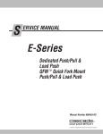
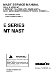
U SER MANUAL 30B Magnetic Layer Picker Swing Model Manual Number 6853927-R1 cascade corporation Cascade is a Registered Trademark of Cascade Corporation C ONTENTS Page INTRODUCTION What The System Does Special Definitions OPERATION Safety Rules Industrial Lift Trucks Handling Loads Auxiliary Valve Functions Operation Safe Operation and Maintenance OSHA Regulations INSTALLATION Truck Requirements Truck Preparation Installation PERIODIC MAINTENANCE 100-Hour Maintenance 500-Hour Maintenance 1000-Hour Maintenance 2000-Hour Maintenance I i 1 2 2 3 3 4 4 5 6 9 17 17 18 18 NTRODUCTION This user manual is for the 30B Magnetizer Layer Picker. Contents include an Operator's Guide, Installation Instructions, Troubleshooting and Periodic Maintenance. Mast NOTE: All specifications are shown in U.S. and (Metric) units where applicable. All fasteners have a torque value range of ±10% of stated value. IMPORTANT: The attachment fittings are JIC. Supply fittings adapted as required for application. What The System Does Upper Carriage Swing Drive The Magnetic Layer Picker is designed to remove an entire layer of cans at one time from a multi-layer stack of steel cans. The entire layer can be transferred to a take-away belt, a retort, or any other area. The magnet can also be used in reverse order to deposit a layer on a pallet. The operation can be repeated to form a multi-layer stack. The cans may be full or empty. The magnetic head, when in the pick-up position, rests on the stripper pan. The cylinder with 1.5 in. (37 mm) stroke is actuated to raise the magnetic head when the cans are to be released, as shown. Telescoping Boom The stripper pan should extend over the edges of the can layer by approximately 1 in. (25 mm) minimum on all four sides. This will establish adequate holding power on the outside can edges, as shown. Magnetic Actuator Cylinder Magnetic Head Stripper Pan Counterweight LP0621.eps i 6853927-R1 I NTRODUCTION Special Definitions The statements shown appear throughout this Manual where special emphasis is required. Read all WARNINGS and CAUTIONS before proceeding with any work. Statements labeled IMPORTANT and NOTE are provided as additional information of special significance or to make the job easier. WARNING: Rated capacity of the truck/ attachment combination is a responsibility of the original truck manufacturer and may be less than shown on the attachment nameplate. Consult the truck nameplate. WARNING – A statement preceded by WARNING is information that should be acted upon to prevent bodily injury. A WARNING is always inside a ruled box. WARNING: Do not operate this attachment unless you are a trained and authorized lift truck driver. CAUTION – A statement preceded by CAUTION is information that should be acted upon to prevent machine damage. IMPORTANT – A statement preceded by IMPORTANT is information that possesses special significance. NOTE – A statement preceded by NOTE is information that is handy to know and may make the job easier. O PERATION Mast This section contains operating instructions for the Cascade Magnetic Layer Picker. It will help you avoid common errors which often cause damage to the equipment or product being handled. This information is intended to simplify operator understanding about effective and safe Magnetic Layer Picker use and operation. Read this information thoroughly before operating the attachment. Be sure you know and understand all operating procedures and safety precautions. If you have any questions, or don’t understand a procedure, ask your supervisor. Swing Drive Carriage Emphasize Safety! Most accidents are caused by operator carelessness or misjudgment. You must watch for poorly maintained equipment and hazardous situations and correct them. CAUTION: Sliding the magnetic assembly on the floor will cause extensive wear to the stripper pan. Avoid this action. WARNING Magnetic Actuator Cylinder Magnetic Head Telescoping Boom Strong Magnetic Field Heart Pacemaker or Medical Device may malfunction. Hand and foot pinch danger by objects attracted to magnet. Stripper Pan Counterweight LP0621.eps Credit Cards, Computer Disks, Storage Devices may be damaged. Label 6854621 LP0645.eps 6853927-R1 1 O PERATION Safety Rules – Industrial Lift Trucks No riders No standing under load or magnetic assembly No reaching through mast LP0622.eps No traveling loaded on ramps P P 3 in. (8 cm) Traveling empty Motor off, park, lower load Overhead Swinging Loads Ground LP0623.eps Watch clearances TRAFFIC STOP Observe Wet floors 2 Workers Stops Bumps Dips Slow for two-way traffic Sound horn, slow at intersection Sound horn, slow at corner 6853927-R1 O PERATION Handling Loads LOAD WEIGHT: Load weight must not exceed the can specifications shown in the chart. LOAD WEIGHT CAN SIZE (Diameter) HOLDING POWER RECOMMENDED MAXIMUM CAN WEIGHT✴ 7.95 in. (202 mm) 2.25 lb (1 kg) 1.5 lb (0.7 kg) 8.30 in. (211 mm) 4.5 lb (2 kg) 3 lb (1.4 kg) 15.74 in. (400 mm) 7 lb (3.2 kg) 5 lb (2.3 kg) 15.80 in. (403 mm) 7 lb (3.2 kg) 5 lb (2.3 kg) 23.74 in. (603 mm) 12 lb (5.5 kg) 9 to 9.5 lb (4.1 to 4.3 kg) ✴ Maximum can weight is based on approximately 3/4 of the maximum holding power. LP0624.eps O PERATION Auxiliary Valve Functions WARNING: Truck control handle and attachment function activation shown here conforms to ASME/ANSI B56.1 recommended practices. Failure to follow these practices may lead to serious bodily injury or property damage. End user, dealer and OEMs should review any deviation from the practices for safe operation. A C E G B D F B H LP0027.eps 2 A D C Magnetic Head 1 LP0625.eps E H G F LP0626.eps Using The Magnetic Assembly Function (G & H) 1 Lower the attachment until the stripper pan contacts the cans to be handled. 2 A Engage (Lower Magnetic Head). 3 Raise the load and transport to desired area. 4 B Release (Raise Magnetic Head). 5 Raise the attachment. CAUTION: Sliding the magnetic assembly on the floor will cause extensive wear to the stripper pan. Avoid this action. 6853927-R1 A Lower Magnetic Assembly B Raise Magnetic Assembly C Swing Left D Swing Right EExtend FRetract G Engage (Lower Magnetic Head) H Release (Raise Magnetic Head) 3 S AFE OPERATION AND MAINTENANCE OSHA Regulations – Industrial Trucks and Attachments (Specific Regulations from OSHA 1910.178) WARNING: The safe operation and maintenance of industrial trucks is regulated by Occupational Safety and Health (OSHA) regulations 1910.178 and American National Standards Institute (ANSI) Safety Standard for Powered Industrial Trucks, ANSI B56.1. When operating and maintaining industrial trucks equipped with attachments you should pay particular attention to the following sections of these regulations. You should be familiar with all sections of these regulations. Ask your employer for the complete regulations. (a) General Requirement (4) Modifications and additions which affect capacity and safe operation shall not be performed by the customer or user without manufacturers prior written approval. Capacity, operation and maintenance instruction plates, tags or decals shall be changed accordingly. (5) If the truck is equipped with front-end attachments other than factory installed attachments, the user shall request that the truck be marked to identify the attachments and show the appropriate weight of the truck and attachment combination at maximum elevation with load laterally centered. (6) The user shall see that all nameplates and markings are in place and maintained in a legible condition. (e) Safety Guards (2) If the type of load presents a hazard, the user shall equip fork trucks with a vertical load backrest extension in accordance with (a)(2) following. (a)(2) All new powered industrial trucks acquired and used by an employer after February 15, 1972 shall meet the design and construction requirements for powered industrial trucks established in the “American National Standard for Powered Industrial Trucks, Part II, ANSI B56.1”, except for vehicles intended primarily for earth moving or over-the-road hauling. (6) A safe distance shall be maintained from the edge of ramps or platforms while on any elevated dock or platform or freight car. Trucks shall not be used for opening or closing freight doors. (10) A load backrest extension shall be used whenever necessary to minimize the possibility of the load or part of it from falling rearward. (n) Traveling (4) The driver shall be required to slow down and sound the horn at cross isles and other locations where vision is obstructed. If the load being carried obstructs forward view, the driver shall be required to travel with the load trailing. (7i) When ascending or descending grades in excess of 10 percent, loaded trucks shall be driven with the load upgrade. (7iii) On all grades the load and load engaging means shall be tilted back if applicable, and raised only as far as necessary to clear the road surface. (o) Loading (1) Only stable or safely arranged loads shall be handled. Caution shall be exercised when handling off-center loads which cannot be centered. (2) Only loads within the rated capacity of the truck shall be handled. (3) The long or high (including multiple-tiered) loads which may affect capacity shall be adjusted. (4) Trucks equipped with attachments shall be operated as partially loaded trucks when not handling a load. (5) A load engaging means shall be placed under the load as far as possible; the mast shall be carefully tilted backward to stabilize the load. (6) Extreme care shall be used when tilting the load forward or backward, particularly when high tiering. Tilting forward with load engaging means elevated shall be prohibited except to pick up a load. An elevated load shall not be tilted forward except when the load is in a deposit position over a rack or stack. When stacking or tiering, only enough backward tilt to stabilize the load shall be used. (l) Operator Training Only trained and authorized operators shall be permitted to operate a powered industrial truck. Methods shall be devised to train operators in the safe operation of powered industrial trucks. (p) Operation of the Truck (m) Truck Operations (1) If at any time a powered industrial truck is found to be in need of repair, defective, or in any way unsafe, the truck shall be taken out of service until it has been restored to safe operating condition. (1) Trucks shall not be driven up to anyone standing in front of a bench or other fixed object. (2) No person shall be allowed to stand or pass under the elevated portion of any truck, whether loaded or empty. (3) Unauthorized personnel shall not be permitted to ride on powered industrial trucks. A safe place to ride shall be provided where riding of trucks is authorized. (1) Any power-operated industrial truck not in safe operating condition shall be removed from service. All repairs shall be made by authorized personnel. (4) The employer shall prohibit arms or legs from being placed between the uprights of the mast or outside the running lines of the truck. (5) All parts of any such industrial truck requiring replacement shall be replaced only by parts equivalent as to safety with those used in the original design. (6) Industrial trucks shall not be altered so that the relative positions of the various parts are different from what they were when originally received from the manufacturer, nor shall they be altered either by the addition of extra parts not provided by the manufacturer or by the elimination of any parts. Additional counter-weighting of fork trucks shall not be done unless approved by the truck manufacturer. (7) Industrial trucks shall be examined before being placed in service and shall not be placed in service if the examination shows any condition adversely affecting the safety of the vehicle. Such examinations shall be made at least daily. When industrial trucks are used on a round-the-clock basis, they shall be examined after each shift. Defects when found shall be immediately reported and corrected. (5i) When a powered industrial truck is left unattended, load engaging means shall be fully lowered, controls shall be neutralized, power shall be shut off and brakes set. Wheels shall be blocked if the truck is parked on an incline. (5ii) A powered industrial truck is unattended when the operator is 25 feet or more away from the vehicle which remains in his view, or whenever the operator leaves the vehicle and it is not in his view. (5iii) When the operator of an industrial truck is dismounted and within 25 feet of the truck still in his view, the load engaging means shall be fully lowered, controls neutralized and the brakes set to prevent movement. 4 (q) Maintenance of Industrial Trucks 6853927-R1 T RUCK REQUIREMENTS WARNING: Rated capacity of the truck/attachment combination is a responsibility of the original truck manufacturer and may be less than that shown on the attachment nameplate. Consult the truck nameplate. Truck Relief Settings Reach, Palletize, 2000 psi (138 bar) Recommended Swing, 2300 psi (160 bar) Maximum Hoist Truck Flow Volume ➀ Min. ➁ Recommended Max. ➂ Reach, Palletize 5 GPM (18 L/min.) 7 GPM (37 L/min.) 10 GPM (56 L/min.) Swing 2 GPM (18 L/min.) 3.5 GPM (13 L/min.) 5 GPM (13 L/min.) Hoist 7 GPM (26 L/min.) 11 GPM (42 L/min.) 15 GPM (57 L/min.) 30A & 30B ➀ ➁ ➂ Cascade Layer Pickers are compatible with SAE 10W petroleum base hydraulic fluid meeting Mil. Spec. MIL-0-5606 or MIL-0-2104B. Use of synthetic or aqueous base hydraulic fluid is not recommended. If fire resistant hydraulic fluid is required, special seals must be used. Contact Cascade. Flow less than recommended will result in slower than normal operating speed. Flow greater than maximum can result in excessive heating, reduced system performance and short hydraulic system life. Hoses and Fittings • Hoist Function – Hoses and fittings for the HOIST function should be No. 8 with .400 in. (10 mm) minimum ID. • Palletize, Reach, Swing Functions – Hoses and fittings for the CLAMP, REACH and SWING functions should be No. 6 with .250 in. (7 mm) minimum ID. GA0144.eps Upper Mast Mounts (tilt cylinders) No tilt function on the Layer Picker. Mast tilt cylinders are replaced with adjustable links to provide a fixed, mast-vertical configuration for all operations. If adjustable links are not provided, contact OEM for cylinder lockout/immobilization. Lower Mast Mounts Clean truck axle or pin mounts and inspect for damage. Repair as necessary. Auxiliary Valve Functions Check that lever movement is in compliance with ANSI standards (B56.1): Swing Left Extend Hoist Down Release GA0082.eps GA0082.eps Hoist Up Swing Retract Right Engage NOTE: Swing function replaces Tilt function (second control lever). 6853927-R1 5 T RUCK PREPARATION Tools Required Pressure Gauge Kit 671212 In addition to a normal selection of mechanic's hand tools, the following are required: Pressure Gauge* No. 6 and No. 8 JIC Swivel Tee No. 6-6 Hose* • Inline Flow Meter Kit: 10 GPM (37 L/min.) - Cascade Part No. 671476. 20 GPM (75 L/min.) - Cascade Part No. 671477. GA0014.eps • Pressure Gauge Kit: No. 4-6 Pipe/JIC* 5000 psi (345 bar) - Cascade Part No. 671212. • Assortment of fittings and hose. No. 6-8 JIC Reducer No. 4, No.6* and No. 8 JIC/O-Ring • Magnetic Protractor/Level for vertical and horizontal adjustments. • Pallet hand truck to install clamp assembly on mast. Quick-Disconnects • Overhead hoisting capability of 4000 lbs. (1815 kg). Male Straight Thread O-Ring Coupler: No. 4 (Part No. 212282)* No. 5 (Part No. 210378) No. 6 (Part No. 678592) • Metric allen wrench set to adjust pressure reliefs. Flow Meter Kit: 671476 (10 GPM - 37 L/min) 671477 (20 GPM - 75 L/min) (2)No. 8-12 JIC/ O-Ring Female JIC Thread Coupler: No. 4 (Part No. 210385)* No. 6 (Part No. 678591) Flow Meter * NOTE: GA0013.eps Diagnostics Kit 394382 includes items marked. (2) No. 6-8 JIC Reducer 1 AC0127.eps Prepare truck for Layer Picker mast A Raise and block the front end of the truck 12 in. (30 cm) per ANSI B56.1, or drive the truck over a service pit. If required, remove existing mast. Clean and inspect mounting areas. B Remove the existing tilt cylinders. NOTE: No tilt function is used with the Layer Picker. Existing tilt cylinders must be replaced with solid adjustable links. Refer to step 4. C Remove the existing tilt cylinder supply hoses. Remove existing tilt cylinder supply hoses C NOTE: Longer hoses are required to connect between the original TILT control section on the truck main valve and, if applicable, the SWING function hose reel on the Layer Picker mast. Remove tilt cylinders WARNING: Cap all open hydraulic supply ports and secure the truck against operation. 6 B LP0042.eps 6853927-R1 T RUCK PREPARATION 2 Install pressure selection and flow control valves (if equipped) A Multi-Position Pressure Selection Valve – Locate valve within safe reach and view of driver. For adjustments see Step 6, Section Step D. B Flow/Pressure Control Valve – Determine location to mount valve. Preferred location is on mast crossmember to enable use of straight fittings and short hose lengths. For adjustments see Step 6, Section Step D. INSTALLATION ON COWL INSTALLATION ON MAST (Preferred) B SWING Circuit Flow/Pressure Control Valve IHR SWING Circuit PALLETIZE Circuit Pressure Gauge IHR PALLETIZE Circuit B Flow/Pressure Control Valve T T P A P A Multi-Position Pressure Selection Valve Multi-Position Pressure Selection Valve LP0197.eps LP0198.eps Return to Tank From Truck Auxiliary Valves (No. 8 Hoses Recommended) From Truck Auxiliary Valves (No. 8 Hoses Recommended) Return to Tank Flow/Pressure Control Valve Ports SWING R SWING L 2/P7 OUTLETS 4/P9 3/P8 1/P6 2 3 4 5 Top View LH Side 1 2 INLETS TANK OPEN 10 GAUGE CLAMP 3 RH Side 4 Bottom View LP0220.eps 6853927-R1 7 T RUCK PREPARATION Hydraulic Connections LAYER PICKER WITH MAGNETIC ASSEMBLY Swing Circuit (if equipped): SWING RIGHT SWING LEFT Reach Extend-Retract Cylinder Magnetic Assembly Actuating Cylinder STOP Valve ENGAGE EXTEND RETRACT HOIST DECEL Valve Swing Valve RELEASE Electronic Swing Control (if equipped) Hoist Cylinders Mast IHR Connections RH Hose Reel P 1 Flow/Pressure Control Valve 6036088 HOIST TP 1 REACH SWING 2 3 Outlets Inlets 2 3 MultiPosition Pressure Selection Valve 4 TANK T 4 PALLETIZE Truck Valves (4) Truck Pump Truck Relief Truck Tank LP0627.eps 8 6853927-R1 I NSTALLATION 1 Install Layer Picker Mast Assembly A Install the bearings in the mast lower axle or WARNING: Mast modifications and additions which affect mast capacity and safe operation shall not be performed by the dealer, customer or user without manufacturer's prior written approval. Capacity, operation and maintenance instruction plates, tags or decals shall be changed accordingly per OSHA regulations 1910.178. pin mounts. Lubricate the bearing surfaces with chassis grease. B Install the mast on the truck. Tighten mounting capscrews using the truck manufacturer's torque specifications. C Install upper mount adjustable links. Using a magnetic protractor/level, adjust the mast for 0-degree tilt during normal operation. D Check that ballast carriage retainer capscrews are tightened to 165 ft.-lbs. (225 Nm). E Check mast anchor chains for proper tension. NOTE: Chains are factory adjusted for correct tension and carriage position. If adjustment is necessary, refer to Step 6. B WARNING: Verify that the overhead hoist and chains or straps are rated for the weight of the attachment. Refer to nameplate for attachment weight. Upper Mount (see illustration lower right) C Ballast Carriage D Retainer Capscrews LP0438.eps Upper Mast Mounts A Lower Mount (Axle mount shown) Adjustable Solid link LP0179.eps 6853927-R1 9 I NSTALLATION 2 Install Magnetic Assembly IMPORTANT: Keep magnetic assembly banded on pallet until securely mounted on Layer Picker boom. D Check that pivot pins and eyepin retainers are in place. A Remove cotter pin, lock tab and spherical Tighten eyepin capscrews to 20 ft.-lbs. (30 Nm). retainer nut from reach cylinder's rod end. E Connect ENGAGE/RELEASE function hoses to valve. B Engage magnetic assembly with boom. Make sure hoses form a loop to allow for boom telescoping movement. CAUTION: Do not twist hoses. Lubricate reach arm bearings with general-purpose chassis lube. C Connect reach cylinder rod end to magnetic assembly bulkhead. Hold hex washer and tighten spherical nut to a torque of 165 ft.-lbs. (225 Nm). NOTE: Joint operates with a loose clearance. F Adjust stops so that magnetic assembly can hang in a level attitude during tier pickup. Refer to Step 6. Cylinder Rod End Anchor (see detail below) A,C Adjustable Stops F B Pallet Hand Truck Boom Magnetic Assembly LP0628.eps Reach Arms D Eyepin Capscrews C Cylinder Rod Spherical Nut, Retainer Cotter Pin LP0225.eps Hex Washer Rod End Anchor 10 6853927-R1 I NSTALLATION 3 Prepare and connect supply hoses Determine hose lengths required for A, B, C and D below. NOTE: For HOIST circuit use No. 8 hose and fittings with a minimum ID of .400 in. (10 mm). For MAGNETIZE, REACH and CLAMP circuits use No. 6 hose and fittings with a minimum ID of .250 in. (7 mm). Cut hoses to length and install hose fittings. IMPORTANT: Use straight or 45 degree fittings wherever possible. Avoid sharp bends or pinch points. Use as few fittings as possible and keep hose lengths to a minimum. If 90 degree connections are required, use tubing type hose end fittings (see illustration) for least flow restriction . Tubing type 90 degree fittings A Hoist – Mast hoist valve to truck main valve (1st control lever). B Swing – RH Hose reel to flow/pressure control valve ports 3 and 4 (3.5 GPM). LP0200.eps NOTE: Swing function does not apply to Stationary Side Mount models. C Reach – RH internal hose reeving to truck auxiliary valve (3rd control lever). D Magnetize – LH internal hose reeving to flow/ pressure control valve ports 1 and 2 (7.5 GPM). B Swing Hoist Swing Flow/Pressure Control Valve Reach Magnetize D Multi-Position Pressure Selection Valve Magnetize Flow/Pressure Control Valve Ports 1/P6 2 3 4 1 2 INLETS Reach A Hoist 5 Top View LH Side C TANK 2/P7 OUTLETS 4/P9 3/P8 10 GAUGE RELEASE SWING R ENGAGE SWING L 3 RH Side Return-to-Tank 4 LP0207.eps Bottom View LP0209.eps 6853927-R1 11 I NSTALLATION 4 Flush supply hoses A Install hoses to truck auxiliary valves. Temporarily connect the other ends together using union fittings. Palletize Swing B Operate auxiliary valves for 30 sec. C Remove union fittings. 5 Reach GA0124.eps Electronic Swing Control, if equipped Use the illustration shown to connect the electrical components to the truck power supply. Refer to Installation Instructions 6158507 for operation and adjustment. NOTE: All cables should be 2-conductor with Deutsch-type connectors. Coil Cord Power Supply/ Communications Group OR Cable Reel Power DECEL Sw DECEL Sol STOP Sw DECEL Limit Switch (Normally Open) Mast STOP Sol STOP Limit Switch (Normally Open) ESC Control Box NOTE: Factory-adjusted time delay relay inside. If necessary, see service manual to change setting. SWING Control Knob Override Pushbutton (Normally Open) 180° and Center Stop STOP Valve IMPORTANT: Pushbuttons that are normally closed, are used only on swing units with center stop (90° position). + DECEL Valve – Carriage Switched Truck Fuse Block Key 12V Truck Battery LP0513.eps IC Trucks – Use chassis ground. Electric Trucks – Use battery ground. 12 6853927-R1 I NSTALLATION 6 Adjustments Accomplish the following adjustments in the order listed below: A MAST AT ZERO-DEGREES TILT – Place a magnetic protractor/level on the front or rear of the mast outer upright. Adjust the adjustable links to provide 0 degrees of tilt. Install retainers and tighten capscrew to 20 ft.-lbs. (30 Nm). IMPORTANT: Final adjustments must be completed at time of delivery to end user, in the location where the Layer Picker will be used, and with actual product loads. IMPORTANT: Make sure the solid adjustable link connections to the mast are tightened properly using truck manufacturer's torque specifications. B LEVEL MAGNETIC ASSEMBLY – Swing the magnetic assembly straight ahead. Place a magnetic protractor/level on the clamp frame or arm as shown. Unscrew the four stops until the clamp hangs freely. Screw the stops down until they contact the boom tubes then back off each 1/2 turn. Tighten locknuts. CAUTION: Boom cylinder and rod end anchor will be damaged if stops are not adjusted properly. Stops must prevent the magnetic assembly from rocking too far forward and backward during load handling. Magnetic Assembly Adjustable Stops, Locknuts Frame Boom Arms Pivot Pins Side View Magnetic Protractor on Mast Upright A Adjustable Solid Links, Retainer B Magnetic Protractor on Magnetic Assembly LP0629.eps 6853927-R1 13 I NSTALLATION Adjustments (Continued) C MAGNETIC ASSEMBLY HEIGHT ABOVE FLOOR: RECOMMENDED MAGNETIC ASSEMBLY UNDERCLEARANCE Adjust the mast chain anchors equally to provide a recommended clearance of 1.5 in. (38 mm) above the floor with the Layer Picker fully lowered. IMPORTANT: When making this adjustment make sure that the mast inner upright does not contact the upper stops on the mast outer upright (arrows). 1-1/2 in. (38 mm) C LP0630.eps Chain Anchors, Double Jam Nuts LP0117.eps 3 Selectable Relief Positions (Driver's Top View) Stops D PRESSURE ADJUSTMENTS (if equipped): 1 2 2 1 • Truck Valves – Adjust main HOIST valve relief on truck to 2600 psi (180 bar). Adjust Auxiliary control valve reliefs to 2300 psi (158 bar). X Adjust the pressure reliefs in the following valves in the order shown: 3 • Pressure/Flow Control Valve – Adjust the valve relief to 2000 psi (138 bar). Flow control is fixed with internal orifices. • Multi-Position Pressure Selection Valve – Adjust the relief cartridges to 750 psi (52 bar) for low setting, 1000 psi (69 bar) for medium setting, and 1200 psi (83 bar) for high setting. Position the stops to block the lever from reaching the "X" valve blockout position (see illustration). IMPORTANT: Pressure settings are a starting point only. Verify by testing with actual loads. Test by picking up a single layer/tier of the load to be handled and look for slippage or creasing. Adjust the low setting if required. Pick up multiple layers/ tiers and look for slippage or creasing. Adjust the medium setting if required. Pick up a maximum number of layers/tiers and look for slippage or creasing. Adjust the high setting, if required. AC0844.eps MULTI-POSITION PRESSURE SELECTION VALVE D PRESSURE / FLOW CONTROL VALVE Adjustable Relief Cartridge Adjustable Relief Cartridges Front View LP0215.eps 14 6853927-R1 I NSTALLATION Adjustments (Continued) E ELECTRONIC STOP POSITION ADJUSTMENT 0° (if equipped): 1 When swinging, the attachment boom should stop at the left, middle and right positions (some units are left and right positions only). Wait 3 seconds to swing after stopping OR press the swing override button to continue swinging. NOTE: A full swing should be 7 to 8 seconds. • If boom stops at middle position, continue with step 2. • If boom stops momentarily and then continues at the middle position: AReduce the hydraulic input pressure for the swing function. OR BAdjust both swing valve side counterbalance Middle Position 90° LP0631.eps Boom swings to left, middle and right positions (some units are left and right positions only). 180° Pressing the override switch allows continuous swing. Wait 3 seconds or press the override button to continue swinging. cartridges CCW in 1/2 turn increments until boom stops at the middle position. • If boom does not stop at the middle position: AInspect the wiring. or pinched cables. Look for loose connection BThe limit switch end rollers are not fully engaging the deceleration ramp in the middle position. Adjust the limit switch actuators to engage the ramp. The ramp can also be adjusted for precision of the stop position. NOTE: The limit switch plungers must be fully depressed. Limit Switches (Normally Open) 2 To continue swing, wait 3 seconds after stopping or press the swing override button to continue swinging the boom. To swing boom without stopping in the middle position, press the override button. LP0390.eps Deceleration Ramp • If the boom does not move off the ramp, switch the positive and negative wire connections to the truck power. The timer is polarity sensitive, not the solenoids. • If boom swings too fast, adjust the restrictor on the STOP Solenoid Valve. Adjust the screw until three threads show past the jam nut. Swing the boom and back out the screw 1/4 turn. Repeat backing the screw 1/4 turn with each swing until the boom slows. The swing boom should gently come to a rest against the mast. STOP Solenoid Valve Adjust restrictor if the boom swings too fast. Swing Valve Counterbalance Cartridge Adjust LP0553.eps LP0391.eps 6853927-R1 15 I NSTALLATION 9 Cycle Layer Picker functions WARNING: Truck control handle and attachment function activation shown here conforms to ASME/ANSI B56.1 recommended practices. Failure to follow these practices may lead to serious bodily injury or property damage. End user, dealer and OEMs should review any deviation from the practices for safe operation. • Check for leaks at fittings, valves and cylinders. • With no load, cycle through all Layer Picker functions several times. • Check for control lever function in accordance with ANSI standards (Ref. ANSI B56.1, "Lever or Handle-Type Controls"). • Pick up and cycle a maximum load, check for proper speeds and smoothness of operation. Auxiliary Valve Functions B A C E G A C D B D F H F LP0027.eps 2 E LP0626.eps Magnetic Head 1 LP0625.eps Using The Magnetic Assembly Function (G & H) H G 1 Lower the attachment until the stripper pan contacts the cans to be handled. 2 G Engage (Lower Magnetic Head). 3 Raise the load and transport to desired area. 4 H Release (Raise Magnetic Head). 5 Raise the attachment. 16 A Lower Magnetic Assembly B Raise Magnetic Assembly C Swing Left D Swing Right EExtend FRetract G Engage (Lower Magnetic Head) H Release (Raise Magnetic Head) CAUTION: Sliding the magnetic assembly on the floor will cause extensive wear to the stripper pan. Avoid this action. 6853927-R1 P ERIODIC MAINTENANCE 100-Hour Maintenance WARNING: After completing any service procedure, always test each function through five complete cycles. First test with no load, then test with a load to make sure the Layer Picker operates correctly before returning it to the job. Every time the lift truck is serviced of every 100 hours of truck operation, whichever comes first, complete the following maintenance on the attachment: • Check for loose or missing fasteners, worn or damaged hoses and hydraulic leaks. • Inspect the stripper pan for damage or wear. Replace as necessary. Mast • Inspect boom cylinder anchor nut for proper connection and tightness. If necessary tighten to 160 ft.-lbs. (220 Nm). • Check that mast is vertical and magnetic assembly is level during normal operation. Adjust as necessary. • Lubricate mast upright rails. Cascade approved lubricants are as follows: Cascade Lube Part No. 599474 – Aerosol Chevron Open Gear Grease – Aerosol Castrol Molub Alloy 936 – Cartridge Swing Boom Carriage Magnetic Assembly IMPORTANT: Regular application of Cascade approved lube will prevent premature mast rail, roller (if equipped) and thrust block wear. 500-Hour Maintenance After each 500 hours of truck operation, in addition to the 100-hour maintenance, perform the following procedures. Stripper Pan • Inspect chains for proper tension and adjustment. • Lubricate full length of mast chains with chain lube (Cascade Part No. 200867). • Check torque value on mast lower mounts and adjustable solid links. • Check torque value on swing boom drive top capscrews. Refer to illustration below. Use cross-pattern and tighten to 160 ft.-lbs. (215 Nm). Swing Boom Drive Capscrews LP0520.eps Swing Drive Motor Capscrews • Check torque value on swing drive motor capscrews. Refer to illustration opposite. Use cross-pattern and double-torque to 450 ft.-lbs. (610 Nm). 6853927-R1 LP0633.eps WARNING: Failure to lubricate uprights properly may result in flaking material that can get into the operator's eyes and cause personal injury. Lubricate areas indicated by heavy line full length of each mast upright every 100 hours. Carriage Inner Upright Outer Upright Load Rollers LP0043.eps 17 P ERIODIC MAINTENANCE 500-Hour Maintenance (Continued) Shim to adjust side clearance • Inspect and adjust (if necessary) the thrust bearing side-to-side clearance in mast upright and carriage. Check carriage alignment and verify that the total sideto-side clearance is 1/16 in. (1.5 mm) maximum at the tightest point throughout the travel of the carriage. Shim behind the thrust bearings for required side-to-side clearance. 1000-Hour Maintenance After each 1000 hours of truck operation, in addition to the 100 and 500-hour maintenance, perform the following procedures: • Inspect boom arm bearings for wear. Replace as necessary. LP0632.eps Shim Adjustment 2000-Hour Maintenance After each 2000 hours of truck operation, in addition to the 100, 500 and 1000-hour maintenance, perform the following procedures: • If equipped, replace thrust bearings in mast and carriage. WARNING: After completing any service procedure, always test each function through five complete cycles. First test with no load, then test with a load to make sure the Layer Picker operates correctly before returning it to the job. 18 6853927-R1 BLANK AMERICAS Cascade Corporation U.S. Headquarters 2201 NE 201st Fairview, OR 97024-9718 Tel: 800-CASCADE (227-2233) Fax: 888-329-8207 Cascade do Brasil Rua João Guerra, 134 Macuco, Santos - SP Brasil 11015-130 Tel: 55-13-2105-8800 Fax: 55-13-2105-8899 Cascade Canada Inc. 5570 Timberlea Blvd. Mississauga, Ontario Canada L4W-4M6 Tel: 905-629-7777 Fax: 905-629-7785 EUROPE-AFRICA Cascade Italia S.R.L. European Headquarters Via Dell’Artigianato 1 37030 Vago di Lavagno (VR) Italy Tel: 39-045-8989111 Fax: 39-045-8989160 Cascade (Africa) Pty. Ltd. PO Box 625, Isando 1600 60A Steel Road Sparton, Kempton Park South Africa Tel: 27-11-975-9240 Fax: 27-11-394-1147 ASIA-PACIFIC Cascade Japan Ltd. 2-23, 2-Chome, Kukuchi Nishimachi Amagasaki, Hyogo Japan, 661-0978 Tel: 81-6-6420-9771 Fax: 81-6-6420-9777 Cascade Korea 121B 9L Namdong Ind. Complex, 691-8 Gojan-Dong Namdong-Ku Inchon, Korea Tel: +82-32-821-2051 Fax: +82-32-821-2055 Cascade-Xiamen No. 668 Yangguang Rd. Xinyang Industrial Zone Haicang, Xiamen City Fujian Province P.R. China 361026 Tel: 86-592-651-2500 Fax: 86-592-651-2571 Cascade Australia Pty. Ltd. 1445 Ipswich Road Rocklea, QLD 4107 Australia Tel: 1-800-227-223 Fax: +61 7 3373-7333 Cascade New Zealand 15 Ra Ora Drive East Tamaki, Auckland New Zealand Tel: +64-9-273-9136 Fax: +64-9-273-9137 Sunstream Industries Pte. Ltd. 18 Tuas South Street 5 Singapore 637796 Tel: +65-6795-7555 Fax: +65-6863-1368 Cascade India Material Handling Private Limited No 34, Global Trade Centre 1/1 Rambaugh Colony Lal Bahadur Shastri Road, Navi Peth, Pune 411 030 (Maharashtra) India Phone: +91 020 2432 5490 Fax: +91 020 2433 0881 c © Cascade Corporation 2014 06-2014 Part Number 6853927-R1