1
Picture Quality Analysis Software
PQASW Data Sheet
Region Of Interest (ROI) on Measurement Execution and Review
Automatic Temporal and Spatial Alignment
Embedded Reference Decoder imported from MTS4EA
Easy Regression Testing and Automation using XML Scripting
(Option ADV) with "Export/Import" File from GUI
Multiple Results View Options
IP Interface with Simultaneous Generation/Capture and 2-Ch Capture
(Option IP)
Embedded Sample Reference and Test Sequences
Available for Customer Installation on the Customer's own PC
Applications
CODEC Design, Optimization, and Verification
Features & Benefits
Fast, Accurate, Repeatable, and Objective Picture Quality Measurement
Predicts DMOS (Differential Mean Opinion Score) based on Human
Vision System Model
Picture Quality Measurements can be made on a Variety of HD Video
Formats (1080i, 720p) and SD Video Formats (525i or 625i)
Makes Picture Quality Comparison across Different Resolutions from
HD to SD, or SD/HD to CIF
User-configurable Viewing Condition and Display Models for Reference
and Comparison (Option ADV)
Attention/Artifact Weighted Measurement (Option ADV)
Conformance Testing, Transmission Equipment, and System Evaluation
Digital Video Mastering
Video Compression Services
Digital Consumer Product Development and Manufacturing
Picture Quality Analysis Software
The PQASW is the Picture Quality Analysis Software based on the concepts
of the human vision system which provides a suite of repeatable, objective
quality measurements that closely correspond with subjective human
visual assessment. These measurements provide valuable information
to engineers working to optimize video compression and recovery, and
maintaining a level of common carrier and distribution transmission service
to clients and viewers.
Data Sheet
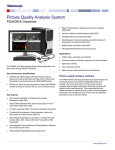
User Interface of PQASW. Showing reference, test sequences, with difference map and
statistical graph.
Compressed Video Requires New Test Methods
The true measure of any television system is viewer satisfaction. While
the quality of analog and full-bandwidth digital video can be characterized
indirectly by measuring the distortions of static test signals, compressed
television systems pose a far more difficult challenge. Picture quality in a
compressed system can change dynamically based on a combination of
data rate, picture complexity, and the encoding algorithm employed. The
static nature of test signals does not provide true characterization of picture
quality.
2
www.tektronix.com
Human viewer testing has been traditionally conducted as described in
ITU-R Rec. BT.500-11. A test scene with natural content and motion
is displayed in a tightly controlled environment, with human viewers
expressing their opinion of picture quality to create a Differential Mean
Opinion Score, or DMOS. Extensive testing using this method can be
refined to yield a consistent subjective rating. However, this method of
evaluating the capabilities of a compressed video system can be inefficient,
taking several weeks to months to perform the experiments. This test
methodology can be extremely expensive to complete, and often the results
are not repeatable. Thus, subjective DMOS testing with human viewers
is impractical for the CODEC design phase, and inefficient for ongoing
operational quality evaluation. The PQASW provides a fast, practical,
repeatable, and objective measurement alternative to subjective DMOS
evaluation of picture quality.
System Evaluation
The PQASW can be used for installation, verification, and troubleshooting
of each block of the video system because it is video technology agnostic:
any visible differences between video input and output from processing
components in the system chain can be quantified and assessed for video
quality degradation. Not only can CODEC technologies be assessed in a
system, but any process that has potential for visible differences can also
be assessed. For example, digital transmission errors, format conversion
(i.e. 1080i to 480p in set-top box conversions), 3-2 pull-down, analog
transmission degradation, data errors, slow display response times, frame
rate reduction (for mobile transmission and videophone teleconferencing),
and more can all be evaluated, separately or in any combination.
Picture Quality Analysis Software — PQASW
How It Works
The PQASW takes two video files as inputs: a reference video sequence
and a compressed, impaired, or processed version of the reference. First,
the PQASW performs a spatial and temporal alignment between the two
sequences, without the need for a calibration stripe embedded within the
video sequence. Then the PQASW analyzes the quality of the test video,
using measurements based on the human vision system and attention
models, and then outputs quality measurements that are highly correlated
with subjective assessments. The results include overall quality summary
metrics, frame-by-frame measurement metrics, and an impairment map for
each frame. The PQASW also provides traditional picture quality measures
such as PSNR (Peak Signal-to-Noise Ratio) as an industry benchmark
impairment diagnosis tool for measuring typical video impairments and
detecting artifacts.
Each reference video sequence and test clip can have different resolutions
and frame rates. The PQASW can provide picture quality measurement
between HD vs SD, SD vs CIF, or any combination. This capability supports
a variety of repurposing applications such as format conversion, DVD
authoring, IP broadcasting, and semiconductor design. The PQASW can
also support measurement clips with long sequence duration, allowing a
video clip to be quantified for picture quality through various conversion
processes.
Prediction of Human Vision Perception
PQASW measurements are developed from the human vision system
model and additional algorithms have been added to improve upon the
model used in the PQA200/300. This new extended technology allows
legacy PQR measurements for SD while enabling predictions of subjective
quality rating of video for a variety of video formats (HD, SD, CIF, etc.). It
takes into consideration different display types used to view the video (for
example, interlaced or progressive and CRT or LCD) and different viewing
conditions (for example, room lighting and viewing distance).
Picture Quality Analysis System
A model of the human vision system has been developed to predict the
response to light stimulus with respect to the following parameters:
Contrast including Supra-threshold
Mean Luminance
Spatial Frequency
Temporal Frequency
Angular Extent
Temporal Extent
Surround
Eccentricity
Orientation
Adaptation Effects
www.tektronix.com
3
Data Sheet
C: Reference Picture
A: Modulation Sensitivity vs. Temporal Frequency
D: Perceptual Contrast Map
The graphs above are examples of scientific data regarding human vision
characteristics used to calibrate the human vision system model in the
PQASW. Graph (A) shows modulation sensitivity vs. temporal frequency,
and graph (B) shows modulation sensitivity vs. spatial frequency. The
use of over 1400 calibration points supports high-accuracy measurement
results.
B: Modulation Sensitivity vs. Spatial Frequency
This model has been calibrated, over the appropriate combinations of
ranges for these parameters, with reference stimulus-response data from
vision science research. As a result of this calibration, the model provides a
highly accurate prediction.
4
www.tektronix.com
Picture (C) is a single frame from the reference sequence of a moving
sequence, and picture (D) is the perceptual contrast map calculated by the
PQASW. The perceptual contrast map shows how the viewer perceives the
reference sequence. The blurring on the background is caused by temporal
masking due to camera panning and the black area around the jogger
shows the masking effect due to the high contrast between the background
and the jogger. The PQASW creates the perceptual map for both reference
and test sequences, then creates a perceptual difference map for use in
making perceptually based, full-reference picture quality measurements.
Picture Quality Analysis Software — PQASW
E: Reference
G: PSNR Map
F: Test
H: Perceptual Difference Map for DMOS
Comparison of Predicted DMOS with PSNR
In the example above, Reference (E) is a scene from one of the VClips
library files. The image Test (F), has been passed through a compression
system which has degraded the resultant image. In this case the
background of the jogger in Test (F) is blurred compared to the Reference
image (E). A PSNR measurement is made on the PQASW of the difference
between the Reference and Test clip and the highlighted white areas
of PSNR Map (G) shows the areas of greatest difference between the
original and degraded image. Another measurement is then made by the
PQASW, this time using the Predicted DMOS algorithm and the resultant
Perceptual Difference Map for DMOS (H) image is shown. Whiter regions
in this Perceptual Contrast Difference map indicate greater perceptual
contrast differences between the reference and test images. In creating
the Perceptual Contrast Difference map, the PQASW uses a human vision
system model to determine the differences a viewer would perceive when
watching the video.
The Predicted DMOS measurement uses the Perceptual Contrast
Difference Map (H) to measure picture quality. This DMOS measurement
would correctly recognize the viewers perceive the jogger as less degraded
than the trees in the background. The PSNR measurement uses the
difference map (G) and would incorrectly include differences that viewers
do not see.
www.tektronix.com
5
Data Sheet
Attention Map Example: The jogger is highlighted
Attention Model
The PQASW also incorporates an Attention Model that predicts focus of
attention. This model considers:
Motion of Objects
Skin Coloration (to identify people)
Location
Contrast
Shape
Size
Viewer Distraction due to Noticeable Quality Artifacts
These attention parameters can be customized to give greater or less
importance to each characteristic. This allows each measurement using an
attention model to be user-configurable. The model is especially useful to
evaluate the video process tuned to the specific application. For example, if
the content is sports programming, the viewer is expected to have higher
attention in limited regional areas of the scene. Highlighted areas within the
attention image map will show the areas of the image drawing the eye's
attention.
Artifact Detection
Artifact Detection reports a variety of different changes to the edges of the
image:
Loss of Edges or Blurring
Addition of Edges or Ringing/Mosquito Noise
Rotation of Edges to Vertical and Horizontal or Edge Blockiness
Loss of Edges within an Image Block or DC Blockiness
They work as weighting parameters for subjective and objective
measurements with any combination. The results of these different
measurement combinations can help to improve picture quality through
the system.
6
www.tektronix.com
Artifact Detection Settings
For example, artifact detection can help answer questions such as: “Will
the DMOS be improved with more de-blocking filtering?” or, “Should less
prefiltering be used?”
If edge-blocking weighted DMOS is much greater than blurring-weighted
DMOS, the edge-blocking is the dominant artifact, and perhaps more
de-blocking filtering should be considered.
In some applications, it may be known that added edges, such as ringing
and mosquito noise, are more objectionable than the other artifacts. These
weightings can be customized by the user and configured for the application
to reflect this viewer preference, thus improving DMOS prediction.
Likewise, PSNR can be measured with these artifact weightings to
determine how much of the error contributing to the PSNR measurement
comes from each artifact.
The Attention Model and Artifact Detection can also be used in conjunction
with any combination of picture quality measurements. This allows, for
example, evaluation of how much of a particular noticeable artifact will be
seen where a viewer is most likely to look.
Picture Quality Analysis Software — PQASW
Edit Measure Dialog
Configure Measure Dialog
Comprehensive Picture Quality Analysis
The PQASW provides Full Reference (FR) picture quality measurements
that compare the luminance signal of reference and test videos. It also
offers some No Reference (NR) measurements on the luminance signal of
the test video only. Reduced Reference (RR) measurements can be made
manually from differences in No Reference measurements. The suite of
measurements includes:
Critical Viewing (Human Vision System Model-based, Full Reference)
Picture Quality
Casual Viewing (Attention Weighted, Full Reference, or No Reference)
Picture Quality
Peak Signal-to-Noise Ratio (PSNR, Full Reference)
Focus of Attention (Applied to both Full Reference and No Reference
Measurements)
Artifact Detection (Full Reference, except for DC Blockiness)
DC Blockiness (Full Reference and No Reference)
The PQASW supports these measurements through preset and
user-defined combinations of display type, viewing conditions, human
vision response (demographic), focus of attention, and artifact detection,
in addition to the default ITU BT-500 conditions. The ability to configure
measurement conditions helps CODEC designers evaluate design
trade-offs as they optimize for different applications, and helps any
user investigate how different viewing conditions affect picture quality
measurement results. A user-defined measurement is created by modifying
a preconfigured measurement or creating a new one, then saving and
recalling the user-defined measurement from the Configure Measure dialog
menu.
Easy-to-Use Interface
The PQASW has two modes: Measurement and Review. The Measurement
mode is used to execute the measurement selected in the Configure Dialog.
During measurement execution, the summary data and map results are
displayed on-screen and saved to the system hard disk. The Review
mode is used to view previously saved summary results and maps created
either with the measurement mode or XML script execution. The user
can choose multiple results in this mode and compare each result side
by side using the synchronous display in Tile mode. Comparing multiple
results maps made with the different CODEC parameters and/or different
measurement configurations enables easy investigation of the root cause
of any difference.
www.tektronix.com
7
Data Sheet
Overlay display, Reference and Map
Integrated Graph
Auto spatial alignment execution with spatial region of interest selected
Six-tiled display
Multiple Result Display
Resultant maps can be displayed synchronously with the reference and test
video in a Summary, Six-tiled, or Overlaid display.
In Summary display, the user can see the multiple measurement graphs
with a barchart along with the reference video, test video, and difference
map during video playback. Summary measures of standard parameters
and perceptual summation metrics for each frame and overall video
sequence are provided.
In Six-tiled display, the user can display the 2 measurement results side by
side. Each consists of a reference video, test video, and difference map to
compare to each other.
8
www.tektronix.com
In Overlay display, the user can control the mixing ratio with the fader bar,
enabling co-location of difference map, reference, and impairments in test
videos.
Error logging and alarms are available to help users efficiently track down
the cause of video quality problems.
All results, data, and graphs can be recalled to the display for examination.
Automatic Temporal/Spatial Alignment
The PQASW supports automatic temporal and spatial alignment, as well
as manual alignment.
The automatic spatial alignment with spatial region of interest in Measure
mode selected independently of the spatial alignment function can measure
the cropping, scale, and shift in each dimension, even across different
resolutions and aspect ratios (for example, when aligning SD to HD video).
If extra blanking is present within the standard active region, it is measured
as cropping when this function is enabled.
The automatic spatial and temporal alignment allows picture quality
measurement between reference and test videos of different resolutions
and frame rates.
Picture Quality Analysis Software — PQASW
Script Sample
Output Spatial ROI on Review mode for in-depth investigation
Import/Export Script in Configure Measure Dialog
Region of Interest
There are two types of spatial/temporal Region of Interest (ROI): Input and
Output. Input ROIs are used to eliminate spatial or temporal regions from
the measurement which are not of interest to the user. For example, Input
Spatial ROI is used when running measurements for reference and test
videos which have different aspect ratios. Input Temporal ROI, also known
as temporal sync, is used to execute measurements just for selected frames
and minimize the measurement execution time.
Output ROIs can be used to review precalculated measurement results
for only a subregion or temporal duration. Output Spatial ROI is instantly
selected by mouse operation and gives a score for just the selected spatial
area. It's an effective way to investigate a specific spatial region in the
difference map for certain impairments. Output Temporal ROI is set by
marker operation on the graph and allows users to get a result for just a
particular scene when the video stream has multiple scenes. It also allows
users to provide a result without any influence from initial transients in the
human vision model. Each parameter can be embedded in a measurement
for the recursive operation.
Automated Testing with XML Scripting
In the CODEC debugging/optimizing process, the designer may want to
repeat several measurement routines as CODEC parameters are revised.
Automated regression testing using XML scripting can ease the restrictions
of manual operation by allowing the user to write a series of measurement
sequences within an XML script. The script file can be exported from or
Result File Sample
imported to the measurement configuration menu to create and manage the
script files easily. Measurement results of the script operation can be viewed
by using either the PQASW user interface or any spreadsheet application
that can read the created .csv file format as a summary. Multiple scripts can
be executed simultaneously for faster measurement results.
www.tektronix.com
9
Data Sheet
Generation/Capture
2-channel Capture
IP Interface
The IP interface enables both generation and capture of compressed video
with two modes of simultaneous operation.
Simultaneous generation and capture lets the user playout the reference
video clips directly from an IP port in the PC into the device under test. The
test output from the device can then be simultaneously captured by the
PC. This saves the user from having to use an external video source to
apply any required video input to the device under test. With this generation
capability, files created by video editing software can be directly used as
reference and test sequences for picture quality measurements.
Simultaneous 2-channel capture lets the user capture two live signals to use
as reference and test videos in evaluating the device under test in operation.
10
www.tektronix.com
In both modes, the captured compressed stream will be decoded to the
uncompressed file by the embedded reference decoder imported from
MTS4EA, and the user can run the picture quality measurement without any
additional tool or manual processes.
Supported File Format for IP Interface
The IP interface option can generate and capture the compressed file in
the following formats:
.mpg
.ts
.trp
Picture Quality Analysis Software — PQASW
Supported File Formats for Measurement
All formats support 8 bit unless otherwise stated, and measurements use
8MSBs:
.yuv (UYVY, YUY2, YUV4:4:4, YUV4:2:0_planar)
.v210 (10 bit, UYVY, 3 components in 32 bits)
.rgb (BGR24, GBR24)
.avi (uncompressed, BGR32 (discard alpha channel) / BGR24 / UYVY
/ YUY2 / v210)
ARIB ITE format (4:2:0 planar with 3 separate files (.yyy, .bbb, .rrr))
.vcap (created by PQA500/600 video capture)
.vcap10 (10 bit, created by PQA500/600 video capture)
Jogger Video File
The following compressed files are internally converted to an uncompressed
file before measurement execution:
Elementary Stream
H.264/AVC/MPEG-4 Part 10 – Baseline, Extended, Main, High 10, High
4:2:2, and High 4:4:4 profiles all levels 1 to 5:1
MPEG-2 – Main Profile at Main, High, and High 1440 levels, 4:2:2 Profile
at Main and High Levels
VC-1 – All Profiles, all Levels
MPEG-4 Part 2 – Simple Profile at Levels 0-5 and Advanced Simple
Profile at Levels 0-5
H.263 Baseline
Avenue Video File
System Layer
Elementary streams contained within:
MPEG-2 Transport/Program Stream
Embedded Sample Video Files
MP4 Parts 1, 12, and 15
ASF
3GPP
DVD VOB
Quicktime MOV
The user can run the measurement with the embedded sample video file when the
software is invoked without valid option key code or dongle.
Video
Description
Jogger
Avenue
Reference, 320×180, 1 Mb/s, 2 Mb/s
Reference, 320×180, 1 Mb/s, 2 Mb/s
www.tektronix.com
11
Data Sheet
Characteristics
Preconfigured Measurement Set (Some measurements are available with Option ADV)
Measurement
Class
Measurement
Name
Display Model
View Video with
No Measurement
"000 View Video"
Configuration Nodes
Perceptual
Artifact
Difference
Detection
View Model
PSNR
NA
NA
NA
NA
SD Broadcast
CRT
HD Broadcast
CRT
CIF/QVGA LCD
(ITU-R BT.500)
NA
(ITU-R BT.500)
Attention
Model
Summary
Node
NA
NA
NA
Typical
NA
NA
PQR Units
NA
Typical
NA
NA
PQR Units
7 scrn heights,
20 cd/m^2
3 scrn heights,
.1 cd/m^2
NA
Typical
NA
NA
PQR Units
NA
Typical
NA
NA
PQR Units
SD Broadcast
CRT
(ITU-R BT.500)
NA
Typical
NA
NA
DMOS Units Re:
BT.500 Training
HD Broadcast
CRT
(ITU-R BT.500)
NA
Typical
NA
NA
DMOS Units Re:
BT.500 Training
CIF/QVGA LCD
7 scrn heights,
20 cd/m^2
3 scrn heights,
.1 cd/m^2
NA
Typical
NA
NA
NA
Typical
NA
NA
DMOS Units Re:
BT.500 Training
DMOS Units Re:
BT.500 Training
SD Broadcast
CRT
(ITU-R BT.500)
NA
Typical
NA
Default
Weightings
DMOS Units Re:
BT.500 Training
HD Broadcast
CRT
(ITU-R BT.500)
NA
Typical
NA
Default
Weightings
DMOS Units Re:
BT.500 Training
CIF/QVGA LCD
7 scrn heights,
20 cd/m^2
(ITU-R BT.500)
NA
Typical
NA
NA
Typical
NA
DMOS Units Re:
BT.500 Training
DMOS Units Re:
BT.500 Training
HD Broadcast
CRT
(ITU-R BT.500)
NA
Typical
NA
SD Broadcast
CRT
(ITU-R BT.500)
NA
Typical
NA
Default
Weightings
Motion and
Foreground
Dominant
Motion and
Foreground
Dominant
Skin and
Foreground
Dominant
Subjective Prediction: Full Reference
Noticeable Differences
SD Display and
Viewing
HD Display and
Viewing
CIF Display and
Viewing
D-CINEMA
Projector and
Viewing
"001 SD
Broadcast PQR"
"002 HD
Broadcast PQR"
"003 CIF and
QVGA PQR"
"004 D-CINEMA
PQR"
DMD Projector
Subjective Rating Predictions
SD Display and
Viewing
HD Display and
Viewing
CIF Display and
Viewing
D-CINEMA
Projector and
Viewing
"005 SD
Broadcast
DMOS"
"006 HD
Broadcast
DMOS"
"007 CIF and
QVGA DMOS"
"008 D-CINEMA
DMOS"
DMD Projector
Attention Biased Subjective Rating Predictions
SD Display and
Viewing
HD Display and
Viewing
CIF Display and
Viewing
SD Sports
HD Sports
SD Talking Head
12
"009 SD
Broadcast
ADMOS"
"010 HD
Broadcast
ADMOS"
"011 CIF and
QVGA ADMOS"
"012 SD Sports
Broadcast
ADMOS"
"013 HD Sports
Broadcast
ADMOS"
"014 SD Talking
Head Broadcast
ADMOS"
www.tektronix.com
SD Broadcast
CRT
DMOS Units Re:
BT.500 Training
DMOS Units Re:
BT.500 Training
Picture Quality Analysis Software — PQASW
Measurement
Class
Measurement
Name
Display Model
Configuration Nodes
Perceptual
Attention
Artifact
Summary
Difference
Model
Detection
Node
Repurposing: Reference and Test are Independent. Use Any Combination Display Model and Viewing Conditions with Each Measurement
View Model
PSNR
Above
Format
Conversion:
Cinema to SD
DVD
Format
Conversion: SD
to CIF
"015 SD DVD
from D-Cinema
DMOS"
DMD Projector
and SD CRT
7 scrn heights,
20 cd/m^2 and
(ITU-R BT.500)
NA
Expert
NA
NA
DMOS Units Re:
BT.500 Training
"016 CIF from
SD Broadcast
DMOS"
LCD and SD
Broadcast CRT
NA
Expert
NA
NA
DMOS Units Re:
BT.500 Training
Format
Conversion: HD
to SD
Format
Conversion: SD
to HD
Format
Conversion: CIF
to QCIF
"017 SD from
HD Broadcast
DMOS"
"017-A SD from
HD Broadcast
DMOS"
"018 QCIF from
CIF and QVGA
DMOS"
SD and HD
Broadcast CRT
(ITU-R BT.500)
and 7 scrn
heights, 20
cd/m^2
(ITU-R BT.500)
NA
Expert
NA
NA
DMOS Units Re:
BT.500 Training
SD and HD
Progressive CRT
(ITU-R BT.500)
NA
Expert
NA
NA
DMOS Units Re:
BT.500 Training
QCIF and
CIF/QVGA LCD
7 scrn heights,
20 cd/m^2
NA
Expert
NA
NA
DMOS Units Re:
BT.500 Training
NA
NA
NA
NA
NA
Default
Weightings
Map units: %
Probability of
focus of attention
NA
Auto-align spatial
Selected
NA
NA
NA
dB units
NA
Auto-align spatial
NA
NA
Blurring
NA
%
NA
Auto-align spatial
NA
NA
NA
%
NA
Auto-align spatial
NA
NA
Ringing /
Mosquito Noise
Edge Blockiness
NA
%
NA
Auto-align spatial
NA
NA
DC Blockiness
NA
%
NA
Auto-align spatial
Selected
NA
Blurring
NA
dB units
NA
Auto-align spatial
Selected
NA
Ringing /
Mosquito Noise
NA
dB units
NA
Auto-align spatial
Selected
NA
Edge Blockiness
NA
dB units
NA
Auto-align spatial
Selected
NA
DC Blockiness
NA
dB units
Auto-align spatial
Selected
NA
All artifacts
selected
NA
dB units
Attention
Attention
"019 Stand-alone
Attention Model"
Objective Measurements: Full Reference
General Difference
PSNR
"020 PSNR dB"
Artifact Measurement
Removed Edges
Added Edges
Rotated Edges
% of Original
Deviation from
Block DC
"021 Removed
Edges Percent"
"022 Added
Edges Percent"
"023 Rotated
Edges Percent"
"024 DC Blocking
Percent"
Artifact Classified (Filtered) PSNR
Removed Edges
Added Edges
Rotated Edges
% of Original
Deviation from
Block DC
"025 Removed
Edges Weighted
PSNR dB"
"026 Added
Edges Weighted
PSNR dB"
"027 Rotated
Edges Weighted
PSNR dB"
"028 DC Blocking
Weighted PSNR
dB"
Artifact Annoyance Weighted (Filtered) PSNR
PSNR w/
Default Artifact
Annoyance
Weights
"029 Artifact
Annoyance
Weighted PSNR
dB"
NA
www.tektronix.com
13
Data Sheet
Measurement
Class
Measurement
Name
Display Model
Format
Conversion:
Cinema to SD
DVD
Format
Conversion: SD
to CIF
"030 SD DVD
from D-Cinema
Artifact weighted
PSNR dB"
"031 CIF from
SD Broadcast
Artifact weighted
PSNR dB"
"032 SD from
HD Broadcast
Artifact weighted
PSNR dB"
"033 QCIF from
CIF and QVGA
Artifact weighted
PSNR dB"
Configuration Nodes
Perceptual
Artifact
Difference
Detection
Repurposing: Use View Model to Resample, Shift, and Crop Test to Map to Reference
Format
Conversion: HD
to SD
Format
Conversion: CIF
to QCIF
View Model
PSNR
NA
Auto-align spatial
Selected
NA
NA
Auto-align spatial
Selected
NA
Auto-align spatial
NA
Attention
Model
Summary
Node
All artifacts
selected
NA
dB units
NA
All artifacts
selected
NA
dB units
Selected
NA
All artifacts
selected
NA
dB units
Auto-align spatial
Selected
NA
All artifacts
selected
NA
dB units
NA
Selected
NA
NA
Default
Weightings
dB units
NA
NA
NA
No-reference
DC Block
NA
% DC Blockiness
Attention-weighted Objective Measurements
General Difference
PSNR
"034 Attention
Weighted PSNR
dB"
NA
Objective Measurements: No Reference
Artifact
DC Blockiness
"035 No
Reference DC
Blockiness
Percent"
NA
Subjective Prediction Calibrated by Subjective Rating Conducted in 2009 with 1080i29 Video Contents and H.264 CODEC
(Refer to application note, 28W_24876_0.pdf)
HD PQR
ITU-BT500 with
Interlaced CRT
HD DMOS
ITU-BT500 with
Interlaced CRT
HD ADMOS
ITU-BT500 with
Interlaced CRT
14
www.tektronix.com
Custom HD CRT
3 scrn heights
NA
Custom
NA
NA
PQR Units
Custom HD CRT
3 scrn heights
NA
Custom
NA
NA
Custom HD CRT
3 scrn heights
NA
Custom
NA
Typical
DMOS Units
Re:BT.500
Training
DMOS Units
Re:BT.500
Training
Picture Quality Analysis Software — PQASW
Nodes (Available with Option ADV)
Options
Node Name
Option
Description
ADV
Advanced Measurement Package (Script execution,
user-configurable measurement, artifact/attention weighting
measurement)
IP Generation/Capture
USB Dongle
Parallel Port Dongle
Add permissions to an existing dongle
Configurable Parameter
Display Model
Display Technology: CRT/LCD/DMD each with preset
and user-configurable parameters (Interlace/Progressive,
Gamma, Response Time, etc). Reference Display and Test
Display can be set independently
View Model
Viewing distance, Ambient Luminance for Reference
and Test independently, image cropping and registration:
automatic or manual control of image cropping and test
image contrast (ac gain), brightness (dc offset), horizontal
and vertical scale and shift
PSNR
No configurable parameters
Perceptual Difference The viewer characteristics (acuity, sensitivity to changes in
average brightness, response speed to the moving object,
sensitivity to photosensitive epilepsy triggers, etc)
Attention Model
Overall attention weighting for measures, Temporal
(Motion), Spatial (Center, People (Skin), Foreground,
Contrast, Color, Shape, Size), Distractions (Differences)
Artifact Detect
Added Edges (Blurring), Removed Edges
(Ringing/Mosquito Noise), Rotated Edges (Edge
Blockiness), and DC Blockiness (Removed detail within a
block)
Summary Node
Measurement Units (Subjective: Predicted DMOS, PQR
or % Perceptual Contrast. Objective: Mean Abs LSB,
dB)., Map type: Signed on gray or unsigned on black.
Worst-case Training Sequence for ITU-R BT.500 Training
(Default or User-application Tuned: Determined by Worst
Case Video % Perceptual Contrast), Error Log Threshold,
Save Mode
IP
USB
PPD
LUD
Language Options
Option
Description
L0
L7
English Manual
Simplified Chinese Manual
Post-sale Upgrade
Option
Description
PQASWUP
ADV
Field Upgrade Kit for PQASW
Advanced Measurement Package (Script execution,
user-configurable measurement, artifact/attention weighting
measurement)
IP Generation/Capture
IP
Ordering Information
Product Selection
PQASW
Feature
PQASW
PQA600
Picture Quality Analysis Software
PSNR, PQR, DMOS Preconfigured Measurements
Multi-resolution/Frame-rate Support
Multi-results View Options
Embedded Reference Decoder
Automatic Temporal and Spatial Alignment
IP Generation/Capture
User-configurable Measurements
Attention/Artifact Weighted Measurements
Script Execution (Batch processing)
Multiple Simultaneous Application Executions
SD/HD SDI Generation and Capture
Cross Video Interface
Code Optimization Designated to the Platform
Yes
Yes
Yes
Yes
Yes
Opt. IP
Opt. ADV
Opt. ADV
Opt. ADV
Opt. ADV
No
No
No
Yes
Yes
Yes
Yes
Yes
Yes
Yes
Yes
Yes
Yes
Opt. SDI
Opt. SDI
Yes
PC Requirement
Characteristic
Description
OS
Processor
Display
RAM
Hard Disk
Windows XP 32-bit or Windows 7 64-bit
Dual core or more
1024×768 or higher resolution
2 GB or greater
1 GB or more for application storage
Included Accessories
Order Number
Description
PQASW Picture Quality Analysis Software Documentation
071-2775-xx
(English)
071-2781-xx
071-2778-xx
063-4284-xx
Quick Start User Manual in English, and Simplified Chinese
or Japanese translation if a language option was ordered
Release Notes
User Technical Reference
Documentation CD, containing PDF files of the
documentation set
Other
020-3054-xx
Application Recovery Disk
Product(s) are manufactured in ISO registered facilities.
Product(s) complies with IEEE Standard 488.1-1987, RS-232-C, and with Tektronix
Standard Codes and Formats.
www.tektronix.com
15
Data Sheet
Contact Tektronix:
ASEAN / Australasia (65) 6356 3900
Austria 00800 2255 4835*
Balkans, Israel, South Africa and other ISE Countries +41 52 675 3777
Belgium 00800 2255 4835*
Brazil +55 (11) 3759 7627
Canada 1 800 833 9200
Central East Europe and the Baltics +41 52 675 3777
Central Europe & Greece +41 52 675 3777
Denmark +45 80 88 1401
Finland +41 52 675 3777
France 00800 2255 4835*
Germany 00800 2255 4835*
Hong Kong 400 820 5835
India 000 800 650 1835
Italy 00800 2255 4835*
Japan 81 (3) 6714 3010
Luxembourg +41 52 675 3777
Mexico, Central/South America & Caribbean 52 (55) 56 04 50 90
Middle East, Asia, and North Africa +41 52 675 3777
The Netherlands 00800 2255 4835*
Norway 800 16098
People’s Republic of China 400 820 5835
Poland +41 52 675 3777
Portugal 80 08 12370
Republic of Korea 001 800 8255 2835
Russia & CIS +7 (495) 7484900
South Africa +41 52 675 3777
Spain 00800 2255 4835*
Sweden 00800 2255 4835*
Switzerland 00800 2255 4835*
Taiwan 886 (2) 2722 9622
United Kingdom & Ireland 00800 2255 4835*
USA 1 800 833 9200
* European toll-free number. If not accessible, call: +41 52 675 3777
Updated 10 February 2011
For Further Information. Tektronix maintains a comprehensive, constantly expanding
collection of application notes, technical briefs and other resources to help engineers working
on the cutting edge of technology. Please visit www.tektronix.com
Copyright © Tektronix, Inc. All rights reserved. Tektronix products are covered by U.S. and foreign patents,
issued and pending. Information in this publication supersedes that in all previously published material.
Specification and price change privileges reserved. TEKTRONIX and TEK are registered trademarks of
Tektronix, Inc. All other trade names referenced are the service marks, trademarks, or registered trademarks
of their respective companies.
10 Mar 2011
www.tektronix.com
28W-26738-0