1
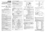
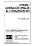
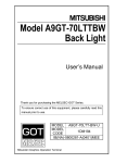
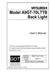
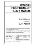
[Precautions for Installation] DANGER A9GT-70STAND z Make sure to shut off all the phases of the system power supply externally before installing a power supply module, wiring, or working on the GOT. There may be a hazard of electric shock or damage to the GOT unless all the phases of the system power supply are shut off. z Make sure to apply the terminal cover to the GOT if the power is to be supplied to the GOT after completing wiring work on the GOT’s power supply terminal. There may be a hazard of electric shock unless the cover is installed. CAUTION User’s Manual Thank you for purchasing the MELSEC-GOT Series. To ensure correct use of this equipment, please carefully read this manual prior to use. z Use the GOT in an environment which satisfies the general specifications described in the GOT900 Series User’s Manual. Using in an environment other than that satisfies the general specifications could cause an electric shock, a fire, or damage or deterioration to the GOT. z Be extremely cautious so that your finger, etc. will not be caught when adjusting the installing angle after removing the angle adjusting screw from the stand. To install the stand to the GOT, fix it securely with the clamp. Then, tighten the mounting screws securely by applying a specified torque in the range of 36 to 48Nym. Loose screws could cause dropping of the GOT. z Make sure that the installing angle of the GOT is 45, 55, 65, or 75 degrees when adjusting it with the stand kept installed to the GOT. The stand would touch and give damage to the GOT if the adjusting angle is not within the range as specified. [Precautions for Wiring] CAUTION Type A9GT-70STAND-U Type 1DM119 Code IB(NA)-68981-C(0406)MEE Mitsubishi Graphic Operation Terminal z Safety Precautions z (Read these precautions prior to use.) z Perform wiring on the GOT appropriately after ensuring its rated voltage and terminal configuration. Using the power supply of a different rating or the wiring error could cause a fire or a malfunction. z To avoid electric shocks, make sure to ground FG and LG terminals, applying Type 3 Grounding. z Tighten the power supply terminal screws to the specified torque of 36 to 48Nym. Loose terminal screws could cause shortcircuit. If overtightened, on the other hand, terminal screws would break or damage the GOT, thereby causing shortcircuit. z Make sure that foreign materials such as chips or waste wires are not caught inside of the GOT, because they could cause failures. z To remove the communications cable or power cable connected to the GOT, never hold and pull the cable itself. Make sure to use a hand to hold the part that is closest and connected to the GOT. Pulling the cable itself with the GOT kept connected could damage the GOT or cable, thereby causing failures. [Precautions for Disposing] When using Mitsubishi equipment, thoroughly read this manual and the associated manuals that are introduced in this manual. Also, pay careful attention to safety and handle the module properly. These precautions apply only to Mitsubishi equipment. Please refer to the relevant user’s manuals for safety precautions pertaining to Mitsubishi programmable controller systems and GOT900 Series Graphics Operation Terminal (abbreviated as GOT, hereafter). The SAFETY PRECAUTIONS in this manual are classified into two categories: DANGER and CAUTION. DANGER CAUTION : Procedures which may lead to a dangerous condition and cause death or serious personal injury if not observed as directed. : Procedures which may lead to a dangerous condition and cause minor to medium personal injury or damage only to property, if not observed as directed. CAUTION • When disposing, treat this product as industrial waste. Manuals The following manuals are relevant to this product. Refer to the following list and order the required manuals. Related Manual Manual Name A985GOT/A975GOT/A970GOT/A960GOT User’s Manual Manual Number (Type Code) SH-4005 (1DM099) Related Manual For relevant manual, refer to the PDF manual stored within the drawing software. Depending on circumstances, procedures indicated with CAUTION could also lead to serious results. In any case, it is important to strictly observe the directions indicated with the above signs. Keep this manual in a place which allows you to easily reach it whenever necessary. Please make sure that the end user of this equipment be provided with this manual. 1998 MITSUBISHI ELECTRIC CORPORATION 1. Introduction 3. Outside Dimensions This manual explains the A9GT-70STAND (Referred to as Stand, hereafter). Stand is used for fixing the GOT at a position which allows an easy view of the GOT’s monitor screen when debugging screen data which is displayed on the GOT, as illustrated below. Stand is designed for common use with A975GOT, A970GOT, and A960GOT. b d a c Type of GOT installed a When A975GOT or A970GOT is installed When A960GOT is installed 314 (12.4) 310 (12.2) b *1 335 (13.2) 300 (11.8) c d *2 304 330 (12.0) (13.0) 337 297 (13.3) (11.7) (Unit : mm(inch)) *1 Front view dimensions. *2 Dimensions for installation angle of 75 degrees Weight kg(lb) 1.48 (3.26) Stand is convenient especially when screen data debugging is performed in the case the GOT is bus-connected by means of an extension cable. When connecting the extension cable, Stand cannot be placed on a desk because the connector comes out from the bottom of the GOT enclosure. Applying Stand to the GOT facilitates screen data debugging on a desk. 2. How to Use STAND 1) Specify a screen according to the GOT (A975GOT, A970GOT, A960GOT) installed. As per the illustrations below, the screen with the larger internal opening identifies A975GOT or A970GOT and that with the smaller internal opening identifies A960GOT. Warranty Mitsubishi will not be held liable for damage caused by factors found not to be the cause of Mitsubishi; machine damage or lost profits caused by faults in the Mitsubishi products; damage, secondary damage, accident compensation caused by special factors unpredictable by Mitsubishi; damages to products other than Mitsubishi products; and to other duties. A975GOT, A970GOT A960GOT 2) Adjust the GOT installing angle with the angle adjusting screw. Adjustable at 45, 55, 65, or 75 degrees. Angle adjusting screw 3) Insert the GOT from the front of Stand and install it to Stand. For how to install, see the A985GOT/A975GOT/A970GOT/A960GOT User’s Manual. 4) After the installation, perform wiring, etc. For safe use y This product has been manufactured as a general-purpose part for general industries, and has not been designed or manufactured to be incorporated in a device or system used in purposes related to human life. y Before using the product for special purposes such as nuclear power, electric power, aerospace, medicine or passenger movement vehicles, consult with Mitsubishi. y This product has been manufactured under strict quality control. However, when installing the product where major accidents or losses could occur if the product fails, install appropriate backup or failsafe functions in the system. Country/Region Sales office/Tel U.S.A Mitsubishi Electric Automation Inc. 500 Corporate Woods Parkway Vernon Hills, IL 60061 Tel : +1-847-478-2100 Brazil MELCO-TEC Rep. Com.e Assessoria Tecnica Ltda. Av. Rio Branco, 123-15 ,and S/1507, Rio de Janeiro, RJ CEP 20040-005, Brazil Tel : +55-21-221-8343 Germany Mitsubishi Electric Europe B.V. German Branch Gothaer Strasse 8 D-40880 Ratingen, GERMANY Tel : +49-2102-486-0 U.K Mitsubishi Electric Europe B.V. UK Branch Travellers Lane, Hatfield, Herts., AL10 8XB,UK Tel : +44-1707-276100 Italy Mitsubishi Electric Europe B.V. Italian Branch Centro Dir. Colleoni, Pal. Perseo - Ingr.2 Via Paracelso 12, 20041 Agrate B., Milano, Italy Tel:+39-039-60531 Spain Mitsubishi Electric Europe B.V. Spanish Branch Carretera de Rubi 76-80 08190 - Sant Cugat del Valles, Barcelona, Spain Tel:+34-935-653135 South Africa Circuit Breaker Industries LTD. Private Bag 2016, Isando 1600, Johannesburg, South Africa Tel : +27-11-928-2000 Hong Kong Ryoden Automation Ltd. 10th Floor, Manulife Tower, 169 Electric Road, North Point, HongKong Tel : +852-2887-8870 Country/Region Sales office/Tel China Ryoden International Shanghai Ltd. 3F Block5 Building Automation Instrumentation Plaza 103 Cao Bao Rd. Shanghai 200233 China Tel : +86-21-6475-3228 Taiwan Setsuyo Enterprise Co., Ltd. 6F., No.105 Wu-Kung 3rd.RD, Wu-Ku Hsiang, Taipei Hsine, Taiwan Tel : +886-2-2299-2499 Korea HAN NEUNG TECHNO CO.,LTD. 1F Dong Seo Game Channel Bldg., 660-11, Deungchon-dong Kangsec-ku, Seoul, Korea Tel : +82-2-3668-6567 Singapore Mitsubishi Electric Asia Pte, Ltd. 307 ALEXANDRA ROAD #05-01/02, MITSUBISHI ELECTRIC BUILDING SINGAPORE 159943 Tel : +65-473-2480 Thailand F. A. Tech Co.,Ltd. 898/28,29,30 S.V.City Building,Office Tower 2,Floor 17-18 Rama 3 Road, Bangkpongpang, Yannawa, Bangkok 10120 Tel : +66-2-682-6522 Indonesia P.T. Autoteknindo SUMBER MAKMUR Jl. Muara Karang Selatan Block A Utara No.1 Kav. No.11 Kawasan Industri/ Pergudangan Jakarta - Utara 14440 Tel : +62-21-663-0833 India Messung Systems Put,Ltd. Electronic Sadan NO:111 Unit No15, M.I.D.C BHOSARI,PUNE-411026 Tel : +91-20-7128927 Australia Mitsubishi Electric Australia Pty. Ltd. 348 Victoria Road, PostalBag, No 2, Rydalmere, N.S.W 2116, Australia Tel : +61-2-9684-7777 HEAD OFFICE : 1-8-12, OFFICE TOWER Z 14F HARUMI CHUO-KU 104-6212, JAPAN NAGOYA WORKS : 1-14, YADA-MINAMI5, HIGASHI-KU, NAGOYA, JAPAN When exported from Japan, this manual does not require application to the Ministry of Economy, Trade and Industry for service transaction permission. Specifications subject to change without notice. Printed in Japan on recycled paper.