1
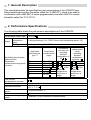
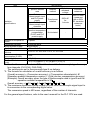
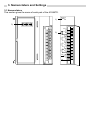
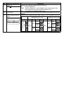
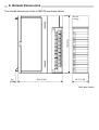
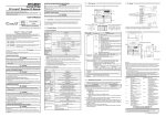
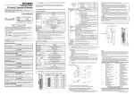
Thermocouple Input Module type A1S68TD User’s Manual (Hardware) Thank you for buying the Mitsubishi general-purpose programmable logic controller MELSEC-A Series Prior to use, please read both this manual and detailed manual thoroughly and familiarize yourself with the product. MODEL A1S68TD-U(HW)-E MODEL 13J780 CODE IB (NA)-66570-C(0211)MEE 1995 MITSUBISHI ELECTRIC CORPORATION z SAFETY PRECAUTIONS z (Always read before starting use) When using this equipment, thoroughly read this manual. Also pay careful attention to safety and handle the module properly. These precautions apply only to this equipment. Refer to the user’s manual of the CPU module to use for a description of the PLC system safety precautions. These "Safety Precautions" classify the safety precautions into two categories: "DANGER" and "CAUTION". DANGER Procedures which may lead to a dangerous condition and cause death or serious injury if not carried out properly. CAUTION Procedures which may lead to a dangerous condition and cause superficial to medium injury, or physical damage only, if not carried out properly. Depending on circumstances, procedures indicated by CAUTION may also be linked to serious results. In any case, it is important to follow the directions for usage. Store this manual in a safe place so that you can take it out and read it whenever necessary. Always forward it to the end user. [DESIGN PRECAUTIONS] CAUTION z Do not bunch the control wires or communication cables with the main circuit or power wires, or install them close to each other. They should be installed 100mm (3.9inch) or more from each other. Not doing so could result in noise that would cause erroneous operation. [INSTALLATION PRECAUTIONS] CAUTION z Use each module in an environment as specified in the “general specification” in the detailed manual. Using the PLC outside the range of the general specifications may result in electric shock, fire or malfunction, or may damage or degrade the module. z Before mounting the module, insert the module fixing hook at the bottom of the module into the fixing hole in the base unit. Improper mounting of the module can cause a malfunction, failure or drop. [WIRING PRECAUTIONS] CAUTION z Always ground the FG terminal to the protective ground conductor.Not doing so can cause a malfunction. z Carry out wiring to the PLC correctly, checking the rated voltage and terminal arrangement of the product. Using a power supply that does not conform to the rated voltage, or carrying out wiring incorrectly, will cause fire or failure. z Tighten the terminal screws to the stipulated torque. Loose screws will cause short circuits, fire, or malfunctions. z Make sure that no foreign matter such as chips or wiring offcuts gets inside the module. It will cause fire, failure or malfunction. [STARTING AND MAINTENANCE PRECAUTIONS] CAUTION z Do not touch the terminals before switching power off externally in all phases. Doing so can cause a malfunction. z Start cleaning or terminal screw retightening after switching power off externally in all phases. Not doing so can cause a malfunction. z Do not disassemble or modify any module. This will cause failure, malfuntion, injuries, or fire. z Mount or dismount the module after switching power off externally in all phases. Not doing so can cause the module to fail or malfunction. [DISPOSAL PRECAUTIONS] CAUTION z When disposing of this product, treat it as industrial waste. About the Manuals The following manuals are also related to this product. In necessary, order them by quoting the details in the tables below. Detailed Manual Manual name Thermocouple input module type A1S68TD User's Manual Manual No. (Model code) IB-66571 (13J781) 1. General Description This manual describes the specifications and nomenclature of the A1S68TD type thermocouple input module (hereafter called the “A1S68TD”), which is be used in combination with a MELSEC-A series programmable controller AnSCPU module (hereafter called the “PLC CPU”). 2. Performance Specifications The following table shows the performance specifications of the A1S68TD. Item Temperature sensor input Detected temperature Output value Scaling value Specification 0 to 1700 16 bit signed binary (0 to 17000 Value to the first decimal place x 10) 16-bit signed binary (0 to 2000) Applicable thermocouple type *1 Applicable thermocouple types and their temperature measurement ranges and accuracy Cold junction compensation accuracy Overall accuracy Maximum resolution Maximum conversion speed Absolute maximum input Number of analogue input points Temperature measurement range B R S K E J 800 to 1700 300 to 1600 300 to 1600 0 to 1200 0 to 800 0 to 750 T 0 to 350 Conversion accuracy (at operating ambient temperature of 25 5 ) 2.5 2 0.5 ot 0.25 of the measured temperature, whichever is larger 1 According to the calculation formula in *2 B, R, S : 0.3 K, E, J, T : 0.1 400 ms/8 channels *3 5V 8 channels +Pt100 connection channel/module Temperature characteristic (when operating ambient temperature varies by 1 ) 0.4 0.3 0.07 ot 0.02 of the measured temperature, whichever is larger Item Specification Specific isolated area Isolation specifications Number of occupied I/O points Connection terminal External power supply Applicable wire size Applicable solderless terminal Internal current consumption (5 VDC) Weight kg (lb) External dimensions mm (inch) Between thermocouple input and PLC power supply Between thermocouple input channels Between cold junction temperature compensation (Pt100) and PLC power supply Dielectric withstand voltage Insulation resistance Transformer isolation 500V AC for 1 minute 5MΩ or more (measured with a 500V DC insulation resistance tester) Not isolated - - Isolation method 32 points 20-terminal block Unnecessary 0.75 to 1.5 mm2 R1.25-3 1.25 YS3, RAV 1.25 3, V1.25 YS3A 0.32A 0.28 (0.61) 130 (5.12)(H) 34.5 (1.36) (W) 93.6 (3.69) (D) *1: Use the thermocouple selector DIP switches to set the thermocouple type for every four channels (CH1-CH4, CH5-CH8). The switches are set to thermocouple type K on delivery. *2: The formula for calculation of overall accuracy is as follows (Overall accuracy) = (Conversion accuracy) + (Temperature characteristic) (Operation ambient temperature version) + (Cold junction compensation accuracy) (Example) Overall accuracy when the type of thermocouple used is type B and the operation ambient temperature is 35 : Overall accuracy = ( 2.5 )+( 0.4 ) (5 ) ( 1 )= 5.5 *3: The maximum conversion speed means the time from thermocouple signal input to its conversion to the corresponding digital value. The conversion speed is 400 msec, regardless of the number of channels. For the general specifications, refer to the user’s manual for the PLC CPU are used. 3. Nomenclature and Settings 3.1 Nomenclature This section gives the name of each part of the A1S68TD. A1S68TD 1) RUN 1 2 3 4 5 6 7 8 3) ON CH1+ 2) R T D - + C + H C 2 H 3 + C + H C 4 H 5 + C + H C 6 H 7 FG C + H 8 FG 1 2 3 4 5 6 7 8 9 10 11 12 13 14 15 16 17 18 19 20 No. Name and appearance Description 1) RUN LED Displays the operation status of the A1S68TD On : Normal operation RUN Flash : Switch setting error, write disabled error, lower/upper limit value setting error, disconnection detected, etc Off : 5 V power cut, watchdog timer error 2) RTD Pt100 RTD for measuring the terminal block temperature (supplied with the module) 3) Thermocouple selector Used to set the thermocouple type used for CH1-CH4 and CH5-CH8. switch Setting for CH1-CH4 Setting for CH5-CH8 1 2 3 4 5 6 7 8 Thermocouple type ON K E J T B R S SW1 SW2 SW3 SW4 SW5 SW6 OFF OFF ON OFF OFF OFF ON ON OFF OFF OFF OFF ON ON ON ON OFF SW7 OFF ON OFF ON SW8 OFF ON OFF ON OFF ON OFF 4. Handling 4.1 Cautions on handling (1) The module case and the terminal block are made of resin. Do not drop the module or subject it to shock. (2) Do not remove the printed circuit board from the module case. This could cause failure. (3) During wiring, take all possible measures to prevent wire scraps or foreign matter from entering the module. If anything enters the module, remove it completely. (4) Tighten the module mounting screws and the terminal screws to the torques specified in the following table: Screw Module mounting screw (M4 screw) Terminal block terminal screw (M3.5 screw) Terminal block mounting screw (M4 screw) Tightening torque range 78 to 118N y cm 59 to 88N y cm 78 to 118N y cm A1S68TD CPU Power supply 4.2 Cautions on installation (1) Do not load an AC voltage I/O module in the right end or left end slot of the A1S68TD. Doing so may cause the I/O module to generate noise, making stable temperature measurement impossible. The AC voltage I/O module can be loaded here. (2) During wiring, follow the instructions in Chapter 5 to prevent noise. 5. Wiring This section gives the cautions on wiring and a connection example for the module. 5.1 Wiring precautions To establish a highly reliable system by making the best use of the A1S68TD functions, external wiring that is not susceptible to the effects of noise is required. The cautions on wiring are presented below. (1) Use separate cables for AC input current and external input signals to the A1S68TD. This can prevent the effects of surge or induction of the AC input current. (2) Keep the thermocouple at least 100mm away from the main circuit and AC control circuit wiring. Provide sufficient space between the thermocouple and circuits that generate high harmonics, such as high-voltage wires and main load circuits, otherwise, the thermocouple will be affected by noise, surge or induction. (3) Generally, ground the shielded wire or shielded cable at one point on the PLC CPU. However, depending on the external noise level, it may be advisable to ground it at an external location. 5.2 Module connection example Input amplifier RTD + - Filter Input amplifier Transformer + - Filter Input amplifier Transformer + - Pt100 CH1 CH8 *1 FG *1: Use a shielded compensating conductor for the cable. 6. Outside Dimensions The outside dimensions of the A1S68TD are shown below. A1S68TD 130 (5.12) RUN 6.5 (2.71) 93.6 (3.69) 0 1 2 3 4 5 6 7 8 9 A B C D E F 34.5 (1.36) Unit: mm (inch) Warranty Mitsubishi will not be held liable for damage caused by factors found not to be the cause of Mitsubishi; machine damage or lost profits caused by faults in the Mitsubishi products; damage, secondary damage, accident compensation caused by special factors unpredictable by Mitsubishi; damages to products other than Mitsubishi products; and to other duties. For safe use y This product has been manufactured as a general-purpose part for general industries, and has not been designed or manufactured to be incorporated in a device or system used in purposes related to human life. y Before using the product for special purposes such as nuclear power, electric power, aerospace, medicine or passenger movement vehicles, consult with Mitsubishi. y This product has been manufactured under strict quality control. However, when installing the product where major accidents or losses could occur if the product fails, install appropriate backup or failsafe functions in the system. Country/Region Sales office/Tel U.S.A Mitsubishi Electric Automation Inc. 500 Corporate Woods Parkway Vernon Hills, IL 60061 Tel : +1-847-478-2100 Brazil MELCO-TEC Rep. Com.e Assessoria Tecnica Ltda. AV. Paulista 1471, Conj. 308, Sao Paulo City, Sao Paulo State, Brazil Tel : +55-11-283-2423 Germany Mitsubishi Electric Europe B.V. German Branch Gothaer Strasse 8 D-40880 Ratingen, GERMANY Tel : +49-2102-486-0 U.K Mitsubishi Electric Europe B.V. UK Branch Travellers Lane, Hatfield, Herts., AL10 8XB,UK Tel : +44-1707-276100 Italy Mitsubishi Electric Europe B.V. Italian Branch Centro Dir. Colleoni, Pal. Perseo-Ingr.2 Via Paracelso 12, 20041 Agrate B., Milano, Italy Tel : +39-039-6053344 Spain Mitsubishi Electric Europe B.V. Spanish Branch Carretera de Rubi 76-80 08190 - Sant Cugat del Valles, Barcelona, Spain Tel : +34-93-565-3131 France Mitsubishi Electric Europe B.V. French Branch 25 Boulevard des Bouvets, F-92741 Nanterre Cedex, France TEL: +33-1-5568-5568 South Africa Circuit Breaker Industries LTD. Tripswitch Drive, Elandsfontein Gauteng, South Africa Tel : +27-11-928-2000 Country/Region Sales office/Tel Hong Kong Ryoden Automation Ltd. 10th Floor, Manulife Tower, 169 Electric Road, North Point, HongKong Tel : +852-2887-8870 China Ryoden Automation Shanghai Ltd. 3F Block5 Building Automation Instrumentation Plaza 103 Cao Bao Rd. Shanghai 200233 China Tel : +86-21-6475-3228 Taiwan Setsuyo Enterprise Co., Ltd. 6F., No.105 Wu-Kung 3rd.RD, Wu-Ku Hsiang, Taipei Hsine, Taiwan Tel : +886-2-2299-2499 Korea HAN NEUNG TECHNO CO.,LTD. 1F Dong Seo Game Channel Bldg., 660-11, Deungchon-dong Kangsec-ku, Seoul, Korea Tel : +82-2-3660-9552 Singapore Mitsubishi Electric Asia Pte, Ltd. 307 ALEXANDRA ROAD #05-01/02, MITSUBISHI ELECTRIC BUILDING SINGAPORE 159943 Tel : +65-6473-2308 Thailand F. A. Tech Co.,Ltd. 898/28,29,30 S.V.City Building,Office Tower 2,Floor 17-18 Rama 3 Road, Bangkpongpang, Yannawa, Bangkok 10120 Tel : +66-2-682-6522 Indonesia P.T. Autoteknindo SUMBER MAKMUR Jl. Muara Karang Selatan Block A Utara No.1 Kav. No.11 Kawasan Industri/ Pergudangan Jakarta - Utara 14440 Tel : +62-21-663-0833 India Messung Systems Put,Ltd. Electronic Sadan NO:111 Unit No15, M.I.D.C BHOSARI,PUNE-411026 Tel : +91-20-712-2807 Australia Mitsubishi Electric Australia Pty. Ltd. 348 Victoria Road, PostalBag, No 2, Rydalmere, N.S.W 2116, Australia Tel : +61-2-9684-7777 HEAD OFFICE : 1-8-12, OFFICE TOWER Z 14F HARUMI CHUO-KU 104-6212, JAPAN NAGOYA WORKS : 1-14, YADA-MINAMI5, HIGASHI-KU, NAGOYA, JAPAN When exported from Japan, this manual does not require application to the Ministry of Economy, Trade and Industry for service transaction permission. Specifications subject to change without notice. Printed in Japan on recycled paper.