1
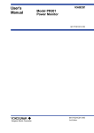
Profile Firstly, thank you for purchasing ISBA-5220A Storage Battery Impendence Analyzer from DADI Telecom. This user manual contains functions introduction, installation, wire connecting, operation and trouble shooting about tester. In order to ensure your correct use, please read this user manual in detailed in advance. And please keep it in convenient place for your quick looking when you encountering problems. Note: We will continue improve and perfect tester functions and characters, so the change of user manual content is without prior notice. We would make effort to perfect this user manual to ensure the accuracy. If you find any fault in this manual, please contact with us. Without the written permission from DADI Telecom, copy and forge is forbidden. All Right Reserved! Contents Including eight chapters: chapter 1 2 3 4 Title Content Overview Product overview. Check tester Introduce all the accessories in the packaging Package. Safety matters Describe how to use tester safely. General Introduce operation attention and operation and use guide use guide 5 6 Tester Introduce the constitute of the tester constitutes main functions Introduce the main functions and and technical technical specifications specifications 7 8 Operation Describe basic operation instruction Common fault Introduce some common fault analysis and phenomenon, reasons and solutions troubleshooting Contents 1 OVERVIEW ............................................................................. 4 2 CHECK TESTER PACKAGING .......................................... 4 3 SAFETY MATTERS .............................................................. 5 4 GENERAL OPERATION AND USE GUIDE ...................... 7 4.1 Operation standard .......................................................... 7 4.2 Use notes .......................................................................... 8 5 TESTER INSTRUMENT ........................................................ 9 5.1 instrument front view ....................................................... 9 5.2 instrument upside and interface ................................... 11 5.3 other parts ........................................................................ 11 6 MAIN FUNCTIONS FEATURES AND TECHNICAL ...... 12 6.1 Functions ......................................................................... 12 6.2 Features .......................................................................... 13 6.3 Specifications ................................................................. 14 7 OPERATION INSTRUCTIONS .......................................... 15 7.1 Instrument’s Power on/off ............................................. 15 7.2 Instruction of tester’s LCD display ............................... 16 7.3 Test Setting ..................................................................... 17 7.3.1 String setting ................................................................18 1 7.3.2 Cell setting................................................................... 22 7.3.3 Joint setting.................................................................. 26 7.3.4 Data storage setting ..................................................... 27 7.3.5 Alarm Threshold Setting.............................................. 28 7.3.6 Test type setting ........................................................... 31 7.3.7 Battery Sampling ......................................................... 32 7.3.8 Impedance Zero Adjustment Functions ....................... 34 7.4 Test Functions................................................................. 36 7.4.1 String Testing .............................................................. 41 7.4.2 Cell Testing ................................................................. 42 7.4. Joint Testing .................................................................. 43 7.4.4 Compare Functions ...................................................... 45 7.4.5 Re-test Functions ......................................................... 47 7.4.6 Gear Setup ................................................................... 48 7.4.7 Data save function ....................................................... 51 7.5 System setting ................................................................ 52 7.5.1 Network setting ........................................................... 53 7.5.2 time setting .................................................................. 53 7.5.3 key voice setting .......................................................... 54 7.5.4 Regularly shutdown setting ......................................... 55 7.5.5 Language setting .......................................................... 56 2 7.5.6 Restore default setting ..................................................57 7.5.7 BackLight setting .........................................................58 7.5.8 Software Version Number ............................................59 7.6 Data Browsing ................................................................ 60 7.6.1 String Data Browsing ...................................................61 7.6.2 Cell Data Browsing ......................................................66 7.6.3 Joint Data Browsing .....................................................68 7.7 PC analysis software operation ................................ 73 7.7.1 profile ...........................................................................73 7.7.2 Installation and uninstall ..............................................73 7.7.3 Menus...........................................................................77 7.7.4 Functions of windows ..................................................81 7.8 instrument charging ....................................................... 89 7.9 Replace instrument battery .......................................... 89 8 COMMON TROUBLE SHOOTING AND SOLUTIONS . 90 3 1 Overview ISBA-5220A Storage Battery Impendence Analyzer is the most powerful and well performed storage battery test equipment. It is a multipurpose impendence instrument and micro ohm meter with the most complete functions and supports the domestic and foreign standards. The equipment can test all kinds of battery like 2V, 4V, 6V, 8V, 12V, 24V, 48V, it can also test resistance of conductor and metal connector, the test precision reaches 1μΩ. The analyzer adapts the VLSI and powerful microprocessor, and can operate the data exchange with RS232, TCP/IP port, meanwhile it adapts the large colorful LCD screen, and the analyzer could achieve the analysis, display and report output of testing data by itself. It is a top grade meter which is suitable for military, communications operators and power department etc. 2 Check tester packaging When you receive the tester, please open the bad, and compare as the package list to check the accessories. If there is some different or you want to add or change some standard or optional accessories, please contact with us. Host: ISBA-5220A battery analyzer host. Standard accessories: Check the accessories to see if they are complete or damaged. 4 Name Spec QTY Test line of alligator clip 1 RS232 parallel seriall Line 1 Ethernet crossed line 1.5 m 1 Charger 8.4V/2.0A User manual 1 1 PC management platform 1 CD Instrument bag 3 Including intima instrument 1 Safety matters In the whole test process, please comply with common safety prevent norms. If you use the tester without this user manual, and the tester is damaged, DADI Telecom won’t undertake any responsibility. Please be sure to obey the following safety norms, lest cause bodily injury or tester damage. Warning Battery charging Charging the battery must use the charger from the manufacturer. You can’t use any unauthorized charger, lest 5 cause tester damage or accident. Battery replacement Please use the manufacturer configured Li batteries. Please refer to 7.9 You can’t operate the tester in inflammable or explosive environment. Do not use the tester in environment with inflammable or explosive liquid or steam. In this environment, it will be dangerous with any electrical instruments. Open rear cover Unless you want to replace modules, please don’t open rear cover or bottom cover. The replace must be operated by formal trained stuff. There is high voltage in some areas inside the tester which will cause dangerous if it is mishandled. LCD If the LCD is damaged and liquid outflows, please don’t inhaled it into mouth or splash on skin. If the liquid is splashed into eye or mouth, please immediately rinse with water and go to the hospital; if the liquid is splashed on skin or clothes, please wipe with alcohol firstly, and then wash with soap and water. In addition, take care, don’t be scratched by glass fragments, don’t touch the border of glass fragments. 6 4 General operation and use guide 4.1 Operation standard Test interface Please connect the wire to test interface, and then connect the wire to tested line. Please don’t touch the bare metal part of test clips, lest there is high voltage on wire. RS232 port Don’t connect with RS232 port with electricity, also don’t short-circuit the interface by metal, otherwise easily damage the internal circuit. Display The new tester has a protective mask on LCD, please rip it before use. Cleaning This tester shell is made of plastic, please use dry and soft cloth to wipe and clean, please do not use a volatile chemical agents, otherwise easy cause discoloring or deformation. Protection of shell and operation panel Please don't spray the volatile chemical reagent onto shell or panel, or don’t make them touch with rubber or PVC for long time, which easy to cause fault. Move tester When you want to move the tester, please check the power wire and cable, to ensure them unconnected with tester, and then take tester by both hands. 7 Longtime unused If the tester is longtime unused, the battery characteristics will getting worse, or the battery need charging. If the charging time is very short and operation time is also short, the tester has to be replaced. Faults If the internal emit strange voice, smell or smoke, please immediately shut off the tester and power supply, and contact us. 4.2 Use notes When you use the tester for the first time, please fully charge the battery. If there appear abnormal pages or crashed, please shutdown the tester and then restart again. Please don’t let the tester in direct sunlight or close to heat place, which maybe cause adverse affect to inside circuit or shell. If the tester is moved to the environment which has higher temperature or temperature changing quickly, the tester will generate condensing. So, the best way is to leave the tester in the new environment one hour before operation. 8 5 Tester Instrument 5.1 instrument front view Display Area Keyboard Host appearance Test Clamp 9 Test line F1 F2 F3 F4 Function Key Esc Enter Return Key Reset Key Tab 1@ 2 ABC 3 DEF 4 GHI 5 JKL 6 MNO Help 7 PQRS 8TUV 9WXYZ 0 A Direction Key Confirm Key Power Key Rst Reset 0 Number Key Rst Pwr Keyboard introduction picture ① instrument buttons It includes power key, reset key, return key, function key,arrow key, OK key and number key. The key functions are as follows: Power key: power on/off. When the tester is on, press this key for a while to close, when the tester appears anomaly and can not be closed through closing icon or power key,press this key for a while (5 seconds) to shut off the tester. Reset key: press this key to reset system. Return key: press this key to return to last menu or cancel setting. Function key: four keys F1,F2,F3 and F4, in different test and setting interface, the function is different. Arrow key: up, down, left, right, move toward corresponding direction by operating different cursor key. 10 OK key: press it for confirmation Number key: 0-9 ten numbers, press this key to input corresponding number. 5.2 instrument upside and interface ① Power Adaptor interface Instrument power adaptor, input 50Hz AC 220V commercial power, allowed error range: ±10%, output 8.4V. ② TEST CABLE test interface TEST CABLE test interface is the special interface for battery resistance test line. ③ Ethernet test interface This interface is standard RJ45 interface, use Ethernet crossed line. ④ RESERVE interface Standby interface ⑤ RS232 interface Professional external RS232 parallel serial Line for the connection between instruments & PC 5.3 other parts ① test line Battery resistance test line, connect with TEST CABLE 11 interface at one end, connect with tested battery at another end, red is positive, black is negative. ② Ethernet line The line equipped with the instrument is crossed network line for connecting with PC. When Ethernet connection is normal, Ethernet indicator on RJ45 interface is on ③ RS232 parallel line Serial line equipped with the instrument is RS232 parallel line, it is connected with PC for tester parameter setting and reading records.。 6 main functions features and technical index 6.1 Functions Voltage, resistance and conductance testing of 0-60V/5AH-6000AH Single cell or battery string. Storage battery impendence test: range is 1μΩ--400 Ω, auto test for entire range, resolution 1µΩ. Storage battery conductance test: range 250 S ~ 50000 S, resolution 1S. Support battery temperature test, data saved in testing records. Support three testing type: String, Cell and Joint test. String date saving amount is 250, each string can 12 includes 430 batteries at most. Joint data saving amount is 250, each string includes 480 strip at most. Cell data saving amount more than 800 strips. Total data saving can reach 220,000 strips. Have comparison test function. Compare the test results with the standard data and show the relationships then indicate the status of the battery. Can set 300 types battery comparison data on the internal instruments, you can select the comparison data as the reference, also can manual input the reference value for compare. Testing data could show is chart, also could in intuitive table. String testing data can display based on string with detail analysis of voltage & impedance & Joint resistance in histogram. With RS232 and TCP/IP port, realize remote control, transmit the filed data to the remote end to analyze and store, generating a lot of analysis data. 6.2 Features Built-in Li battery, operate by hands, support external power supply operation, work over 8 hours without external power. High speed test. Each cell testing is within 10 seconds, and the string testing is done within a few minutes. Large storage capacity: Store large capacity test data (over 220,000 items) Display mode: with light touch operation button and 3.5〞true color LCD backlight 13 Built-in high precision clock and calendar, each test data with auto test time record; Adapt wide temperature chip: normally work under -10~+50℃, satisfies many tests under adverse circumstances; Strong structure is suitable for field work. 6.3 Specifications GENERAL INDEX Size 190×108×50 (mm) Weight 1Kg Display LCD,320*240 Impendence test and Test range:1µΩ~400Ω precision Other Gear:±0.8%rdg ± 6dgt Voltage test Precision:4mμO:±1.0%rdg ± 8dgt Test range:DC 0~60V Precision: ±0.1%rdg ± 6dgt Temperature Tester range:-30℃~100℃ test Precision: ±1℃ Data storage Over 220,000 record items Operation method Communications way Keyboard RS232、RJ45 14 Working -10℃~+50℃ temperature Relative 0~80%RH humidity Storage and transportation -20℃~+70℃ temperature Power supply Built-in Li battery charging continues working > 8 hours Power adaptor (8.4V/2.0A) 7 Operation Instructions 7.1 Instrument’s Power on/off 1) Power on Instrument: Click the power on/off button, and it will display LOGO icon and then enter into the below operation display: 15 2011-05-10 09:01:23 STRING TEST 测试设置 2) Power off instrument: A long press the power on/off button, about 5 seconds. 7.2 Instruction of tester’s LCD display It will show the main display when power on the tester. It includes: Battery indicator, Date and time, function icon, 16 Date And Time Function Name Capacity Display 2011-05-10 09:01:23 STRING TEST Function Ico 测试设置 It includes series function icon, and each icon indicates a function. Please click the related icon to enter into the display. 7.3 Test Setting Functions description: Please process the parameter setting before test. It include: String setting, Cell setting, Joint setting, Data Storage, Alarm Threshold setting, test type setting, Battery sampling and zero resistance setting. Use methods: Select the related setting items, click <Enter> icon enter into the right display. When the display shows in gray color it means that the display was under browse mode without any parameters setting. Detail as follow: 17 Navigation Date \Time And Power 2011-05-10 09:01:23 TEST SETTING Settings functions 1. String Mode: 2. Cell Mode: 3. Joint Mode: 4. Save Mode: 5. Set Warning: 6. Input Comp: 7. Set Test Type: 8. Sample Test: function keys Station:01 String:01 U Type:2 V-0500AH U Warning:02.00V REF: 000.483mΩ Esc Settings content Enter 7.3.1 String setting Functions description: Set the String setting parameters like: Station No., Group No., Battery type, Low pressure alarm value and Group reference value. Battery type includes battery voltage type and capacity. Low pressure alarm value is the alarm threshold value of the measured battery, the instruments will alarm when the measured voltage lower than the threshold one. It should process Alarm threshold and test type setting before String setting. Details please check the chapter “Alarm Threshold Setting” and “Test Type Setting”. Use methods: Select the “String Mode” on the main test setting display and click <Enter> icon to process the String testing. 18 When you process the String Mode, the battery type, alarm threshold, reference value and others all in gray color, it shows that the string is already exist and you can not make change. Please amend Group No. and Station No. to build a new string and then set the related string parameters. There have shortcut keys of some parameters, for the one do not have shortcut keys, User’s can input NO.. Detail as follow: 2011-05-10 09:01:23 TEST SETTING 1. String Mode: 2. Cell Mode: 3. Joint Mode: 4. Save Mode: 5. Set Warning: 6. Set Test Type: 7. Sample Test: 8. Zero Setting: Station:01 String:01 U Type:2 V U Warning:02.10V REF: 000.483mΩ Esc Enter Support voltage type: 2V、4V、6V、8V、12V、24V. Click related shortcut keys for setting, like below: 19 2011-05-10 09:01:23 TEST SETTING 1. String Mode: 2. Cell Mode: 3. Joint Mode: 4. Save Mode: 5. Set Warning: 6. Set Test Type: 7. Sample Test: 8. Zero Setting: 2V Station:01 String:01 U Type:2 V- 0500AH U Warning:02.10V REF: 000.483mΩ 6V 4V More Comparison threshold value setting include: Manual Input directly or Select threshold value. Select threshold means choose the Built-in set value. The Build-in values can get directly from the sampling battery testing or the configured download software. Details please take the chapter “Sampling Battery” for reference. Display of Manual Input value as follow: 20 2011-05-10 09:01:23 TEST SETTING 1. String Mode: 2. Cell Mode: 3. Joint Mode: 4. Save Mode: 5. Set Warning: 6. Set Test Type: 7. Sample Test: 8. Zero Setting: Esc Station:01 String:01 U Type:2 V- 0500AH U Warning:02.10V REF: 000.483mΩ Input Srlect Enter During Conductance testing type, manual input threshold value display as follow: 2011-05-10 09:01:23 TEST SETTING 1. String Mode: 2. Cell Mode: 3. Joint Mode: 4. Save Mode: 5. Set Warning: 6. Set Test Type: 7. Sample Test: 8. Zero Setting: Esc Station:01 String:01 U Type:2 V- 0500AH U Warning:02.10V REF: 2027S Srlect Input Enter Select the saved threshold value, click function key <-1><+1> to change the serial No. and choose value. It will show in Gray color if it can not configure. The display of 21 select threshold value as follow: 2011-05-10 09:01:23 TEST SETTING 1. String Mode: 2. Cell Mode: 3. Joint Mode: 4. Save Mode: 5. Set Warning: 6. Set Test Type: 7. Sample Test: 8. Zero Setting: Esc Station:01 String:01 U Type:2 V- 0500AH U Warning:02.10V REF: 001 2V:0500AH:0.483mΩ Srlect Input Enter 7.3.2 Cell setting Functions description: Set the Cell setting parameters like: Battery type, Low pressure alarm value and reference value. Battery type includes battery voltage and capacity. Low pressure alarm value is the alarm threshold value of the measured battery, the instruments will alarm when the measured voltage lower than the threshold one. Use methods: Comparison threshold value setting include: Manual Input directly or Select threshold value. Select threshold means choose the Built-in set value. The Build-in values can get directly from the sampling battery testing or the configured download software. Details please take the chapter 22 “Sampling Battery” for reference. Display of Cell setting as follow: 2011-05-10 09:01:23 TEST SETTING 1. String Mode: 2. Cell Mode: 3. Joint Mode: 4. Save Mode: 5. Set Warning: 6. Set Test Type: 7. Sample Test: 8. Zero Setting: 2V U Type:2 V- 0500AH U Warning:02.10V REF: 000.483mΩ 4V 6V More Support voltage type: 2V、4V、6V、8V、12V、24V. Click related shortcut keys for setting, like below: 2011-05-10 09:01:23 TEST SETTING 1. String Mode: 2. Cell Mode: 3. Joint Mode: 4. Save Mode: 5. Set Warning: 6. Set Test Type: 7. Sample Test: 8. Zero Setting: 2V U Type:2 V- 0500AH U Warning:02.10V REF: 000.483mΩ 4V 6V 23 More Comparison threshold value setting include: Manual Input directly or Select threshold value. Select threshold means choose the Built-in set value. The Build-in values can get directly from the sampling battery testing or the configured download software. Details please take the chapter “Sampling Battery” for reference. When the test type is resistance, the display of manual input threshold value of Cell setting as follow: 2011-05-10 09:01:23 TEST SETTING 1. String Mode: 2. Cell Mode: 3. Joint Mode: 4. Save Mode: 5. Set Warning: 6. Set Test Type: 7. Sample Test: 8. Zero Setting: Esc Srlect U Type:2 V- 0500AH U Warning:02.10V REF: 000.483mΩ Input Enter During Conductance testing type, manual input threshold value display as follow: 24 2011-05-10 09:01:23 TEST SETTING 1. String Mode: 2. Cell Mode: 3. Joint Mode: 4. Save Mode: 5. Set Warning: 6. Set Test Type: 7. Sample Test: 8. Zero Setting: -1 U Type:2 V- 0500AH U Warning:02.10V REF: 2027S Input Srlect +1 Select the saved threshold value, click function key <-1><+1> to change the serial No. and choose value. It will show in Gray color if it can not configure. The display of select threshold value as follow: 2011-05-10 09:01:23 TEST SETTING 1. String Mode: 2. Cell Mode: 3. Joint Mode: 4. Save Mode: 5. Set Warning: 6. Set Test Type: 7. Sample Test: 8. Zero Setting: -1 U Type:2 V- 0500AH U Warning:02.10V REF: 001 2V:0500AH:0.483mΩ Srlect Input 25 +1 7.3.3 Joint setting Functions description: Set the string setting parameters like: Station No., Group No., Group reference value and Pole No.. Pole No. means the Pole No. of Cell battery. It should process Alarm threshold and test type setting before Joint. Details please check the chapter “Alarm Threshold Setting” and “Test Type Setting”. Use methods: When you process the Joint setting, the Pole No., reference value and others all in gray color, it shows that the string already exists and you can not make changes. Please amend Group No. or Station No. to build a new string and then set the related string parameters. It is Manual input type of Joint reference value setting. Pole No. means the Pole No. of each Cell battery, the serial No. of Joint is based on the No. of Pole. During resistance testing, the display of Joint setting as follow: 26 2011-05-10 09:01:23 TEST SETTING 1. String Mode: 2. Cell Mode: 3. Joint Mode: 4. Save Mode: 5. Set Warning: 6. Set Test Type: 7. Sample Test: 8. Zero Setting: Station: 01 String:01 REF:000.050mΩ Post Per JAR:2 Esc Enter During Conductance testing type, manual input threshold value display as follow: 2011-05-10 09:01:23 TEST SETTING 1. String Mode: 2. Cell Mode: 3. Joint Mode: 4. Save Mode: 5. Set Warning: 6. Set Test Type: 7. Sample Test: 8. Zero Setting: Station: 01 String:01 REF:20000 S Post Per JAR:2 Esc Enter 7.3.4 Data storage setting Functions description: 27 Set the related parameters of String testing, Cell testing, Joint testing and data storage saving. There are two saving types of data storage: Manual & Auto When you set Manual saving, you should click the related saving keys to store the data. If you set Auto saving, the instruments will auto saving the date once the testing results coming stable. Use methods: Select the data storage saving type and click OK key to enter into. The display as follow: 2011-05-10 09:01:23 TEST SETTING 1. String Mode: 2. Cell Mode: 3. Joint Mode: 4. Save Mode: 5. Set Warning: 6. Set Test Type: 7. Sample Test: 8. Zero Setting: Esc Save Mode Of Data String Mode: Manual Cell Mode: Manual Joint Mode: Manual Manual Auto Enter Click up & down key to select the items you want to setting, click <Manual> <Auto> function key to choose the saving type. 7.3.5 Alarm Threshold Setting Functions description: 28 Set the alarm & replacement value of the battery resistance. If test battery’s resistance, the setting value should be the multiple of the reference value. If test conductance, the setting value should be the percentage of the reference value. Use methods: Select the alarm threshold setting and enter into the setting display, if it is resistance testing, the display as follow: 2011-05-10 09:01:23 TEST SETTING 1. String Mode: 2. Cell Mode: 3. Joint Mode: 4. Save Mode: 5. Set Warning: 6. Set Test Type: 7. Sample Test: 8. Zero Setting: Esc Warning:1.5 REF Instead:2.0 REF +0.1 -0.1 Enter Click up & down keys to select the items you want to set. Click <+0.1><-0.1> function key to set the alarm and replacement threshold and then save. The alarm & replacement value should be the multiple of the reference resistance value. 1.5REF means the instrument will warning and alarm when the testing results 1.5 times greater and 2 times less than the reference value. 2.0REF means the instrument will process replacement alarm when the testing value 2 times greater than the measured 29 value. During Conductance testing type, manual input threshold value display as follow: 2011-05-10 09:01:23 TEST SETTING 1. String Mode: 2. Cell Mode: 3. Joint Mode: 4. Save Mode: 5. Set Warning: 6. Set Test Type: 7. Sample Test: 8. Zero Setting: Esc +1% Warning:65% REF Instead:50% REF -1% Enter Click up & down keys to select the items you want to set. Click <+1%><-1%> function key to set the alarm and replacement threshold and then save. The alarm & replacement value should be the percentage of the reference conductance value. 65%REF is the alarm threshold value, it will process warning and alarm when the test value 50% lower than the reference value. 50%REF is the replacement threshold value, it will alarm when the test value lower than the measured value 50%RE. 30 7.3.6 Test type setting Functions description: Set the test type. There are two type for setting: Resistance and Conductance. Note: Change test type is only effective for Cell testing. For the String and Joint testing, the test type can not changed, as the test type is already confirmed before you set up the testing string. If you want to amend the test type of String & Joint testing, you should re-build testing string. Use methods: Select the test type setting and enter into the display show as follow: 2011-05-10 09:01:23 TEST SETTING 1. String Mode: 2. Cell Mode: 3. Joint Mode: 4. Save Mode: 5. Set Warning: 6. Set Test Type: 7. Sample Test: 8. Zero Setting: Esc Set Test Type: Resistance R G Enter Click <R> <G> function key to set the testing type. 31 7.3.7 Battery Sampling Functions Introduction Battery sampling used to setup a test reference value by this way. Thus this value downloads to the unit by PC software configuring a reference value. Totally, for reference values, storage capacity is over 300 items. How to use Select battery sampling and click the confirm key to enter into the below interface: 2011-05-10 09:01:23 TEST SETTING 1. String Mode: 2. Cell Mode: 3. Joint Mode: 4. Save Mode: 6. Set Test Type: 6. Set Test Type: 6. Set Test Type: 8. Zero Setting: Esc Sample Test: NO. 001 002 003 004 005 006 Set Comp U 12V 2V 2V 2V 2V 2V AH 45 500 1000 100 2000 200 Page Up REF 6.500 mΩ 0.380 mΩ 0.200 mΩ 1.000 mΩ 0.100 mΩ 0.500 mΩ Next Click <page Up><Next> to check the reference value, by up and down key selecting the current reference number, click <Set Comp>key to enter into battery sampling interface as below: 32 2011-05-10 09:01:23 TEST SETTING 1. String Mode: 2. Cell Mode: 3. Joint Mode: 4. Save Mode: 5. Set Warning: 6. Set Test Type: 7. Sample Test: 8. Zero Setting: Sample Test: REF Number: 001 Sample:30 Capability:0500AH U-Type:2V Test Range:4 mΩ Esc Sampling Click Up/down key to select setup options, and according to battery actual parameter to setup the sample parameter. We suggest to use new battery for sampling while the sample number no less than 10 items is highly recommended . When setup finished, click <Sampling> key enter into the sampling interface as below: 2011-05-10 09:01:23 Sample Test Sample:30 REF Number:001 R 0 . 421 (mΩ) Sample NO.1 Range:4 mΩ Save Esc 33 Save test results once data became stable until all samples are tested, at this time, the test interface will display Min and Average value. According to actual needs, click <Save Ave>or<Save Min> keys to setup the average value or min value as reference value and complete the battery sampling’s operation. As long as click <Esc> key you could drop out battery sampling, of course, reference values are not be saved at last. 2011-05-10 09:01:23 Sample Test Sample:30 REF Number:001 R 0 . 421 (mΩ) Sample NO.30 Min:0.412(mΩ) Average:0.432(mΩ) Range:4 mΩ Esc Save Ave Save Min 7.3.8 Impedance Zero Adjustment Functions Functions Introduce This impedance zero functions is used to calibrate the tester by adjusting impedance 0 range value, in order to make the test results are much more reliable. When difference of environment temperature and normal temperature 25℃ is over 10℃ or above this value, we would suggest to use zero adjustment function. Correct 34 and properly use zero adjustment function that can improve measurement accuracy. Note: In below description that mentioned zero adjustment board is in good conductive metal plate, when zero adjusting, you have to try two test clip or probe as close as possible. How to use Select impedance zero adjustment function and click confirm key enter into following interface: 2011-05-10 09:01:23 TEST SETTING 1. String Mode: 2. Cell Mode: 3. Joint Mode: 4. Save Mode: 5. Set Warning: 6. Set Test Type: 7. Sample Test: 8. Zero Setting: Func On Zero Adjust 0.000(mΩ) Range:4mΩ Function OFF Func Off Range Save Click <Range> key to switch zero gear; click <Function On> <Function off> to select zero adjustment function on or off. It will display on the test interface when functions on. As test clip and zero adjustment board connected, click <Save> key to complete selected gear zero adjustment but to be make sure test cable and board connection well. If other gear need to zero adjustment just repeat the above operation. If the zero adjustment is not 35 correct and the zero adjustment is on as testing, that would cause the test results are incorrect, as this time zero adjustment is necessary for incorrect gear before use. 7.4 Test Functions Functions Introduce Test functions contain three methods: string testing, Cell testing and Joint testing. Each function adapts to different type of testing. String testing is used to the whole battery testing, and that can manage the series number of battery test results, and analysis the data, find out the inequality Cell battery in fast way. View data and check out battery Chartic so that search invalid battery rapidly. Cell test is used to test every kinds of Cell battery, that can test and setup different types of test parameter. Joint testing inspects each of battery Joint and generate graphic when data viewing, that can quickly find the failure Joint. Impedance gear has six types(4mΩ、40mΩ、400m Ω、4Ω、40Ω、400Ω), when gear setup auto switch, it would auto switch measure range according to different impedance value. During the range switch, impedance value becomes unstable, only when value range is stable and impedance measurement value to stabilized, in this case you can complete the impedance results compare and save. Temperature measurement must equip with a temperature probe or clip to test and display temperature value. Prior to compare functions, they need to set the reference value (input or test battery sample to obtain the reference value). This tester support 300 items compare data. The set of reference value can be done by PC 36 software or by tester. In order to learn details please refer to “Battery sampling” Chapter. How to use Connect the top of unit “TEST CABLE” interface by a test cable and fix it. The other end clip the battery positive/negative, red clip connect positive, while black clip connect the negative as below: “Test clip” connect to battery terminal sketch When test type is resistance test, the interface is as below: 37 Function tip Test function Station\ String\NO. Test Content Range function keys STRING TEST Adjust Station:01 U State tip Date \Time And Power 2011-05-10 09:01:23 Testing Auto String:01 Test mode instructs Cell No.002 R 2 . 1 1 2 (V) 0 . 5 37 (mΩ) Test results indicate T 25.0 (℃) Reference and Comparison results Range:4 mΩ REF : <0.483mΩ> Cancel Esc Range 1.11 REF Save Test type is conductivity test interface as below: Function tip Test function Station\ String\NO. Test Content STRING TEST Adjust Station:01 U State tip 2011-05-10 09:01:23 Testing Auto String:01 Test mode instructs Cell No.002 G 2 . 1 1 2 (V) 1862 ( S ) Test results indicate T 25.0 (℃) Reference and Comparison results REF : <2070S> function keys Date \Time And Power Esc Cancel Range 89% REF Save Test function Three types: String testing, Cell testing and Joint testing Function Prompt Prompt when zero adjustment is on, but not prompt when zero adjustment is off. Status Prompt Auto test: When test clip or probe is connected to battery, it will display 38 “Testing”, and also display “Saved” if the data already saved. Manual test: When save data it will display “Saved” and disappear after 1 second. Battery Time Indication Display current time and battery left capacity. Test method indication Test method includes two types: Manual test and auto test, manual test must need press keys by hand that can save test data, auto test that tester auto test and save data automatically. Group, Station, Battery number display Display current group, station, battery number three types of test status and display them in different ways. Test display Display test results, string testing and Cell testing display: voltage, impedance and temperature, Joint display impedance and temperature. Gear Display impedance test use the current gear, if the test type is conductivity that would not display gear. Functional keys Four functions correspondence to F1-F4 keys, in difference functions has different interfaces. 39 Reference value and results compare “R REF:0.483 mΩ” stands for reference value, 0.483 mΩ,“1.11R REF”stands for tested impedance value is 1.11 times of reference value. When impedance and ( Test types voltage test value marked as is resistance) means test values does not exceed the alarmed threshold. Otherwise, tested value marked as that means tested battery voltage is exceed alarms. Tested impedance marked as means test results are exceeded replaced value of configured threshold. When impedance marked as that means compare result is greater than warning value of setup alarm threshold. Reference value and compare results (Test type is conductivity) “ REF : 2070S ” stands for 2070S , “ 89%R REF ” stands for test conductivity reference value is 89%. When impedance and voltage value marked as means test value exceed alarm threshold, battery status is normal, but if test voltage marked as that means battery voltage is lower than alarms, impedance marked as 40 means compare results lower than replaced value of setup alarm threshold. As tested impedance marked as and then the compare results are lower than warning value of alarm threshold as well as higher than replaced value. Note: · Test cable and battery must have good connection otherwise it will affect test results. · When test value display “Over” that means the impedance exceed test range. ·When test value display “------”, that means test cable open or test cable is cut off. When test cable connected improperly or tested item value is over exceed the test range it will display “------” 7.4.1 String Testing Functions Introduce When perform the string testing, can test battery voltage, impedance, and temperature at the same time. How to use Click String testing icon that may enter into 41 the string testing interface as below: 2011-05-10 09:01:23 Manual STRING TEST Station:01 U String:01 R 2 . 1 1 2 (V) 0 . 5 37 (mΩ) T 25.0 (℃) REF : <0.483mΩ> Range:4 mΩ Esc Cancel Range Cell No.002 1.11 REF Save Connection method can refer to “Test Functions” Chapter Before string testing you have to setup parameter of test strings, detailed operation please go for the “String Testing Setup” Chapter. When complete the setup if alarm threshold need changed again or test type is invalid to current test strings. Each string can save 430 items battery, in the condition of manual test, save data has to wait until test data to be stabilized. 7.4.2 Cell Testing Functions Introduce When tester performs Cell testing, that can test battery voltage, impedance and temperature at the same time. How to use: 42 Click Cell testing icon that can enter into Cell test interface such as follows: 2011-05-10 09:01:23 Saved Manual CELL TEST Cell No.002 U R 2 . 1 1 2 (V) 0 . 5 37 (mΩ) T 25.0 (℃) Range:4 mΩ Esc REF : <0.483mΩ> Cancel Range 1.11 REF Save Connect method please refer to the “Test Functions” Chapter. Before Cell testing please setup Cell parameter, detailed operation method refer to “Cell Testing Setup” Chapter. Each alarm threshold changing and test type of current Cell are valid. Cell testing can save at least 800 items test results. In the condition of manual testing, save data have to wait until results data to be stabilized. 7.4. Joint Testing Functions Introduce 43 When tester perform Joint testing, it can test impedance and temperature of Joint How to use: Click Joint icon, and then enter into the Joint test interface as follows: 2011-05-10 09:01:23 Saved Manual JOINT TEST Station:01 String:01 R 0 . 5 37 (mΩ) T 25.0 (℃) Range:4 mΩ REF : <0.483mΩ> Esc Cancel Range Joint:002-1 1.11 REF Save Connection method please refer to Chapter “Test Functions” Before Joint testing please setup the parameter of Joint first, detailed operation method please refer to “Joint Test Setup” Chapter. When this setup completes, alarm threshold changing and testing type of current test strings are all invalid. Data save method can be changed during string testing. Each string can save at least 480 items data. Under the circumstances of manual testing, manual save data have to wait for data is stable. 44 7.4.4 Compare Functions Functions Introduce Compare function that means compare current test result and setup reference value, thereby in this way to judge tested battery health status. Before compare functions, you need to setup comparator (input or test battery sample to obtain reference value), this tester support 300 items data compare. Comparator setup can be down by PC software or also by tester. Please go for detailed operation method by chapter “Battery Sampling” How to use: At the test interface click <Comp> key on or <Cancel> off this function, when compare function is on it will display compare results (as follows) When test type is impedance: “R REF:0.483 mΩ” stands for reference value is 0.483 mΩ,“1.11R REF ” stands for tested impedance value is 1.11 times of reference value. Impedance and voltage value marked as that means test result is under alarm threshold value, battery status is normal, but if test voltage marked as that means tested voltage is too low and alarming, test impedance marked as the result of comparison is larger than replaced value of alarm threshold settings, the measured battery is in failure in need of replacement. 45 Once impedance marked as compare results is larger than warning value of alarm threshold but lower than replaced value of alarm threshold, that indicates battery needs more maintenance, as follows: 2011-05-10 09:01:23 Saved Manual STRING TEST Station:01 U String:01 R 2 . 1 1 2 (V) 0 . 5 37 (mΩ) T 25.0 (℃) Range:4 mΩ Esc REF : <0.483mΩ> Cancel Range Cell No.002 1.11 REF Save When test type is in the mode of Conductivity, “R REF: 2070S”that means reference value is 2070S, “89%R REF” that means tested conductivity reference value is 89%. When impedance and voltage test value checked by means test results didn’t exceed alarm threshold, and also battery status in normal. If voltage checked by icon that means measured battery voltage is too low and alarming, while impedance checked by means compare results is lower than changed valued of alarm threshold setting and it in need of replacement. If 46 conductivity is checked by icon means compare results lower than warning value of alarm threshold but higher than replaced value, in this case battery need more maintenance, as follows: 2011-05-10 09:01:23 Saved Manual STRING TEST Station:01 U String:01 G 2 . 1 1 2 (V) 1862 ( S ) T 25.0 (℃) REF : <2070 S> Esc Cancel Cell No.002 89% REF Save 7.4.5 Re-test Functions Functions Introduce In the circumstances of auto save, three test modes are all have Re-test functions, when test clip still connect with tested battery, you need to re-test the battery again, the new test data can overlay last auto save test data. How to use: In the circumstances of auto test, if last test data is not correct, you can test battery again by clicking re-test key when test clip is connected with battery, this function can 47 be use repeatedly as follows: 2011-05-10 09:01:23 Saved Auto STRING TEST Station:01 U String:01 R 2 . 1 1 2 (V) 0 . 5 37 (mΩ) T 25.0 (℃) REF : <0.483mΩ> Range:4 mΩ Esc Cancel Range Cell No.002 1.11 REF Retest Note: when using re-test functions battery number or Joint number would not able to add automatically, but it would overlay last test data, and if test clip or probe disconnected with battery, tester would regard that last test is over and jump to next test automatically, so it is not correct to click re-test key when test cable and battery already disconnected. 7.4.6 Gear Setup Functions Introduce In order to save time of gear auto switch plus that impedance of multi-battery is in the same test range, you can setup correspondence “Gear” to test How to use: 48 In the test interface click <Range> functional keys to setup gears. After click gear key the functional keys would change to gear setup keys, as follows: 2011-05-10 09:01:23 Manual CELL TEST Cell No.001 U R 2 . 1 1 2 (V) 0 . 5 37 (mΩ) T 25.0 (℃) Range:4 mΩ 4 mΩ REF : <0.483mΩ> 40 mΩ 400 mΩ 1.11 REF More Confirm selection by clicking related gear, click <More> functional keys would display other gears setup, as follows: 49 2011-05-10 09:01:23 Manual CELL TEST Cell No.001 U R 2 . 1 1 2 (V) 0 . 5 37 (mΩ) T 25.0 (℃) Range:4 mΩ REF : <0.483mΩ> 4 Ω 40 Ω 400 Ω 1.11 REF More Confirm selection by clicking related gear, click <More> functional keys would display other gears setup, as follows: CELL TEST 2011-05-10 09:01:23 Manual Cell No.001 U R 2 . 1 1 2 (V) 0 . 5 37 (mΩ) T 25.0 (℃) Range:4 mΩ REF : <0.483mΩ> 1.11 REF Auto More Esc 50 Click <More> functional keys would display first page gear setup; click <Esc> functional keys would drop out gears switch functions and get back functional keys of test interface, click <Auto> gear functional keys would select a proper gear to test. 7.4.7 Data save function Function introduction: By manual save, the three test methods all have data save function. Data save function will put the test data in inventory. Using method: By manual save, press the <Save> function key, the test data will be saved, and the test Numbers will add 1 automatically, as following: 2011-05-10 09:01:23 Saved Manual CELL TEST Cell No.002 U R 2 . 1 1 2 (V) 0 . 5 37 (mΩ) T 25.0 (℃) Range:4 mΩ Esc REF : <0.483mΩ> Cancel Range 51 1.11 REF Save 7.5 System setting Function introduction: It is for system time setting, network parameter setting, key voice setting, timing shutdown setting, language setting, restore default setting, BackLight setting, and software version No. view function. Using method: Click system setting icon, you will enter into system setting choose window. The setting content in gray says that it is in browsing mode, and doesn’t set specific parameters, as following: Navigation Date \Time And Power 2011-05-10 09:01:23 SYSTEM Settings functions function keys 1. Net Set: 2. Time Set: 3. Sound Set: 4. Self-off: 5. Language: 6. Factory Set: 7. Backlight: 8. Version: IP :010. 001. 092. 141 MASK:255. 255. 255. 000 PORT : 06800 Esc Settings content Enter After choose the setting item, press<Enter>, you will enter into the related setting window. 52 7.5.1 Network setting Function introduction: It is used for configuring network interface parameters, including IP address, the network mask and port No.. Using method: After selecting the network setting item, press<Enter>, you will enter into the network configuration window. As following: 2011-05-10 09:01:23 SYSTEM 1. Net Set: 2. Time Set: 3. Sound Set: 4. Self-off: 5. Language: 6. Factory: 7. Backlight: 8. Version: IP :010. 001. 092. 141 MASK:255. 255. 255. 000 PORT : 06800 Esc Enter Move to the number which you want to modify by direction key, press number key to input numbers, press<Enter> to save, press<Esc>to quit the network configuration, and won’t save it. 7.5.2 time setting Function introduction: 53 It is used to set time and date. Using method: After choose the time setting item, press<Enter>, you will enter into the time setting window. As following: 2011-05-10 09:01:23 SYSTEM 1. Net Set: 2. Time Set: 3. Sound Set: 4. Self-off: 5. Language: 6. Factory Set: 7. Backlight: 8. Version: 2000 - 02 - 02 14 : 12 : 24 Esc Enter Move to the number which you want to modify by direction key, press number key to input numbers, press<Enter> to save, press<Esc>to quit the time setting, and won’t save it. 7.5.3 key voice setting Function introduction: It is used to set the switch of key voice. Usage: After choose the key voice setting item, press<Enter>, 54 you will enter into the key voice setting window. As following: 2011-05-10 09:01:23 SYSTEM 1. Net Set: 2. Time Set: 3. Sound Set: 4. Self-off: 5. Language: 6. Factory Set: 7. Backlight: 8. Version: Esc Sound Set:ON ON OFF Enter Press<ON>or<OFF>to set key voice, press<Enter> to save, press<Esc>to quit the key voice setting, and won’t save it. 7.5.4 Regularly shutdown setting Function introduction: It is used to set the time of timing shutdown. Usage: After choose the timing shutdown setting item, press<Enter>, you will enter into the Regularly shutdown setting window. As following: 55 2011-05-10 09:01:23 SYSTEM 1. Net Set: 2. Time Set: 3. Sound Set: 4. Self-off: 5. Language: 6. Factory Set: 7. Backlight: 8. Version: 10 Min 20 Min Self-off:10 Min 30 Min 60 Min Press<10 Min>,<20 Min >,<30 Min>or<60 Min>to set the shutdown time<10 Min>,<20 Min >,<30 Min>or<60 Min>, press<Enter> to save, press<Esc>to quit the key voice setting, and won’t save it. 7.5.5 Language setting Function introduction: Setting the tester using language, now the 5220A supports Chinese and English. Usage: After choose the language setting item, press<Enter>, you will enter into the language setting window. As following: 56 2011-05-10 09:01:23 SYSTEM 1. Net Set: 2. Time Set: 3. Sound Set: 4. Self-off: 5. Language: 6. Factory Set: 7. Backlight: 8. Version: Esc English Language: English 简体中文 Enter Press<English>or< 简 体 中 文 >to set language, press<Enter> to save, press<Esc>to quit the key voice setting, and won’t save it. 7.5.6 Restore default setting Function introduction: It is used to restore the system setting parameters to be the default parameters. Usage: After choose the restore default setting item, press<Enter>, you will enter into the restore default setting window. As following: 57 2011-05-10 09:01:23 SYSTEM 1. Net Set: 2. Time Set: 3. Sound Set: 4. Self-off: 5. Language: 6. Factory Set: 7. Backlight: 8. Version: Esc Restore factory settings Determined to restore the factory settings? Cancel Enter press<Enter> to restore the default parameters and save, press<Esc>to quit the setting, and won’t save it. 7.5.7 BackLight setting Function introduction: It is used to set the LCD display BackLight. Usage: After choose the BackLight setting item, press<Enter>, you will enter into the BackLight setting window. As following: 58 2011-05-10 09:01:23 SYSTEM 1. Net Set: 2. Time Set: 3. Sound Set: 4. Self-off: 5. Language: 6. Factory Set: 7. Backlight: 8. Version: Esc Backlight:11 -1 +1 Enter Press<+1>or<-1>to set BackLight, press<Enter> to save, press<Esc>to quit the BackLight setting, and won’t save it. 7.5.8 Software Version Number Functions It is for the review of the software version number. Usage: Review the software version number by selecting the number. 59 2011-05-10 09:01:23 SYSTEM 1. Net Set: 2. Time Set: 3. Sound Set: 4. Self-off: 5. Language: 6. Factory Set: 7. Backlight: 8. Version: VERSION:V2.0 Esc 7.6 Data Browsing Function Introduction It is used to browse the testing record of string, cell and Joint. The string data has the functions of data analysis, Chart for resistance and voltage. The max value, min value and average value can be got by string data analysis. There is no data analysis for cell which can just review the testing data. Usage Select the icon of data browsing and click <Enter> to the interface. There are three kinds of testing records, string data, cell data Joint in this interface. 60 2011-05-10 09:01:23 DATA BROWSE -> STRING BROWSE Select the target icon and press <Enter>. 7.6.1 String Data Browsing Functions Introduction It ‘s for the browsing of string data which display the base station number, string number, batteries in the string and saving time of the last battery. The string tests the deletion of a string and strings. Browse the testing data of each string, testing data analysis, voltage Chart and resistance Chart. Usage Select the icon of string data and press <Enter>. 61 2011-05-11 09:01:23 DATA BROWSE -> STRING BROWSE R Data Station String 01 01 01 02 01 03 01 04 01 05 01 06 01 07 01 08 Page Up Total 005 020 030 046 050 043 052 033 Test Time 2011-05-10 09:03:23 2011-05-10 11:10:20 2011-05-10 13:20:32 2011-05-10 14:50:29 2011-05-10 15:10:53 2011-05-10 16:01:13 2011-05-10 16:35:50 2011-05-10 17:03:25 Next Clear DEL One Select the target string by arrow keys and press <Enter>. Previous page and next page keys are used for shift pages. String data supports string deletion. Press <DEL One> can delete the selected data. Press <Clear> can delete all data. Shift strings by arrow keys and the follow is a sample for a string data records. 62 STRING BROWSE NO. U (V) R (mΩ) T (℃) n*REF Result TimeH/M DateM/D 2011-05-11 09:01:23 Station:01 String:01 003 001 002 2.112 2.112 2.112 0.568 0.566 0.568 25.0 25.0 25.0 1.17 1.17 1.17 PASS PASS PASS 09:02 09:02 09:02 06/02 06/02 06/02 REF : <0.483mΩ> 004 2.112 0.568 25.0 1.17 PASS 09:03 06/02 Analyse Page Up 005 2.112 0.570 25.0 1.18 PASS 09:03 06/02 Next Press <Analyse> in the string data and data analysis is preceded. Max value, min value and average value can be generated by data analysis. STRING BROWSE NO. U (V) R (mΩ) T (℃) Result State H/M/S Y/M/D Switch Max 005 2.112 0.570 25.0 1.17 PASS 09:15:21 11/06/02 2011-05-11 09:01:23 Resistance Min 002 2.112 0.566 25.0 1.17 PASS 09:03:29 11/06/02 REF : <0.483mΩ> Average 2.112 0.568 25.0 Chart There are two ways for data analysis: resistance analysis and voltage analysis. The users can press the 63 corresponding keys to get through. Applied mode will be showed in the navigation bar. Press <Chart>, a Chart will be showed under the current analysis mode. The max value, min value and average value will be showed in the voltage Chart. There are 32 batteries in each page and shift page by pressing previous page and next page. 2011-05-10 09:01:23 Valtage Chart (V) Max:2.113 Average:2.112 Min:2.111 2.000 1 Esc 5 Page Up Next There are max value, min value, average value, reference line and alarm line in resistance Chart. It shows 32 batteries in each page and the user can shift pages by the corresponding keys. 64 2011-05-10 09:01:23 Resistance Chart (mΩ) Max:0.570 Average:0.568 Min:0.566 Warn 0.483 1 Esc 5 Page Up Next If conductance is tested in the string, a conductance Chart will be generated. And the max value, min value and average vale will be found in it. t shows 32 batteries in each page and the user can shift pages by the corresponding keys. 65 2011-05-10 09:01:23 Conductance Chart (S) Max:1766 Average:1750 Min:1754 2070 Warn 1754 1-1 退出 Page Up Next v If there is no string data or the data has been deleted, it will show the following interface. 2011-05-10 09:01:23 DATA BROWSE -> STRING BROWSE NO TEST DATA OF STRING Esc 7.6.2 Cell Data Browsing Function Introduction: 66 It is used for the review of cell test data. The use can view all the data by shifting pages. All cells test data deletion. Usage Select cell browsing icon , and press <Enter>. 2011-05-10 09:01:23 DATA BROWSE -> CELL BROWSE Cell NO. 001 002 003 004 005 006 007 008 Page Up Test Time 2011-05-10 09:01:23 2011-05-10 11:10:20 2011-05-10 13:20:32 2011-05-10 14:50:29 2011-05-10 15:10:53 2011-05-10 16:01:13 2011-05-10 16:35:50 2011-05-10 17:03:25 Clear Next Select the target testing serial by arrow keys and press <Enter>. The user can shift pages for more records. All cell testing data can be deleted by <Clear>. The user can press arrow keys to select the target records. 67 2011-05-10 09:01:23 DATA BROWSE -> CELL BROWSE NO. U (V) R (mΩ) T (℃) Result State Time H/M/S Date Y/M/D Esc 001 2.112 0.568 25.0 1.17 PASS 09:01:23 11-5-10 REF : <0.483mΩ> Up Down If there is no cell data or the data has been deleted, it shows the following interface. 2011-05-10 09:01:23 DATA BROWSE -> CELL BROWSE NO TEST DATA OF CELL Esc 7.6.3 Joint Data Browsing Function Introduction: 68 To review all the records in Joint, it will show the base station number, group number, batteries in the string and saving time of the last battery. The Joint tests string deletion and dele all records in Joint. Browse the testing data of each Joint, data analysis and Chart. Usage: Select the icon of Joint browsing and press <Enter>. 2011-05-10 09:01:23 R Data DATA BROWSE -> JOINT BROWSE Station String 01 01 01 02 01 03 01 04 01 05 01 06 01 07 01 08 Page Up Total 005 020 030 046 050 043 052 033 Test Time 2011-05-10 09:01:23 2011-05-10 11:10:20 2011-05-10 13:20:32 2011-05-10 14:50:29 2011-05-10 15:10:53 2011-05-10 16:01:13 2011-05-10 16:35:50 2011-05-10 17:03:25 Next Clear DEL One Press arrow keys to select the target data and press <Enter>. The user can shift pages for more records. String data supports cell deletion. The selected data can be deleted by <DEL One> and all data can be deleted by <Clear>. The user can press arrow keys to select the target records. 69 JOINT BROWSE NO. R (mΩ) T (℃) Result State TimeH/M DateM/D 2011-05-10 09:01:23 Station:01 String:01 001-1 002-1 003-1 004-1 0.568 0.566 0.568 0.568 25.0 25.0 25.0 25.0 1.17 1.17 1.17 1.17 PASS PASS PASS PASS 09:02 09:02 09:03 09:04 06/02 06/02 06/02 06/02 005-1 0.570 25.0 1.18 PASS 09:05 06/02 REF : <0.483mΩ> Page Up Analyse Next There is data analysis function in the testing data of Joint. Press <Analyse> and it will analyzer the current data. Please refer to the following graph. 2011-05-10 09:01:23 Analyse NO. R (mΩ) T (℃) Result State H/M/S Y/M/D Max Min 005-1 002-1 0.566 0.570 25.0 25.0 1.17 1.18 PASS PASS 09:05:10 09:02:30 10/06/02 10/06/02 REF : <0.483mΩ> Average 0.568 25.0 Chart Esc A Chart can be displayed in the interface of data analysis. Press <Chart> will generate the Chart of current 70 data. It will show max value, min value, average value, reference line and alarm line in the resistance Chart. Each page will display 32 batteries and the user can shift pages for more records. 2011-05-10 09:01:23 Resistance Chart (mΩ) Max:0.570 Average:0.568 Min:0.566 Warn 0.483 1 Esc 5 Page Up Next If test type of Joint is conductance, it will show the conductance Chart with max value, min value, average value, reference line and alarm line. Each page will display 32 batteries and the user can shift pages for more records. 71 2011-05-10 09:01:23 Conductance Chart (S) Max:1766 Average:1750 Min:1754 2070 Warn 1754 1-1 退出 Page Up Next If there is no data of Joint or all data has been deleted, it shows the following: 2011-05-10 09:01:23 DATA BROWSE -> JOINT BROWSE NO TEST DATA OF JOINT Esc 72 7.7 PC analysis software operation 7.7.1 profile BatteryManage is a PC management software developed by DADI for ISBA-5220A. It can communicate with ISBA-5220A by RS-232 serial interface or TCP/IP network interface. Main functions: 1) Read the testing records and save them in the computer; 2) Print the records in computer; 3) Delete the records; 4) Delete the records saved in computer;; 5) Synchronous clock; 6) Read or allocate equipment; the parameters of the 7) Read or allocate the comparison reference data; 8) Analyzer the testing data and generate the Chart for resistance, conductance or voltage. 7.7.2 Installation and uninstall 1) Installation 1. Double click “BatteryTM_Setup.exe” and begin the installation of BatteryManage. 73 2. Select the target language and click “next”; 3. Pop up the box of “Installation - Battery Test Manage” and click “next”; 4. Click “browse” to locate the software and 74 click “next”. If locate as default, click “next”. 5. Shortcut for the location of program, recommend to use default setting and click “next”.. 6. The options for adding shortcuts, recommend to use default setting and click “next”. 75 7. Installation preview. Click “Installation”. 8. Click “finish” to retreat the program and complete the installation. 2) uninstall 1. Double click “unins000.exe” to uninstall the software. 76 2. Click “Yes” in the popping up dialogue box of Battery Test Manage. 3. Click “Confirm” to retreat the program and complete the uninstall. 7.7.3 Menus There are 4 menus in this software and refer to the following table for details: 77 Item Drop-down menu Functions Historical data Open the window of “Historical data” Log out Deactivate the software parameter Open the window of “Parameter” Communication parameter Open the window of “Local communication parameter” Read Cell data Open “Cell data” window to read testing data in current communication mode. Read string data Open “string data” window to read testing data in current communication mode. Read Joint data Open “Joint data” window to read testing data in current communication mode. About Display the version number and copyright. file Parameter Testing data Help 78 There are 4 operation window in the software and to get more in the following table. Item Functions Historic Data Display entire testing data saved in computer and print. Read equipment parameter Set equipment parameter Synchronous equipment clock Set comparison reference data of equipment and save it in computer. Set comparison parameter (write the comparison reference data in equipment.) Read string testing data (to display and read string testing data saved in equipment.) Delete string data (delete string testing data saved in equipment.) String Data Save string data (Save the string testing data read from the equipment to computer and display them in historic data window.) Resistance analysis(display the selected resistance Chart and analyzer the max value, min value and average value. 79 Voltage analysis ( display the selected voltage Chart and analyzer the max value, min value and average value.) Read cell testing data(display and read the cell testing data saved in equipment.) Cell Data Delete cell data (delete cell testing data saved in equipment.) Save cell data (Save the cell testing data read from the equipment to computer and display them in historic data window.) Read Joint testing data (to display and read Joint testing data saved in equipment.) Joint Data Delete Joint data (delete Joint data saved in equipment.) Save Joint data (Save the Joint testing data read from the equipment to computer and display them in historic data window.) Resistance analysis(display the selected resistance Chart and analyzer the max value, min value and average value. Communication parameter Set serial interface communication parameters (Set serial interface ID, Serial interface communication baud rate) 80 Set network communication parameters (set IP address and interfaces of the equipment) 7.7.4 Functions of windows 1)Local communication configuration Please configure the communication parameter before other operations to make sure the proper use of software and equipment. The following configuration: is the local communication The serial communication parameters are used to set up a computer system communicating with the equipment's serial number. 81 Communication speed (serial communication baud rate) 115200。 ISBA-5220A doesn't support the other baud rate. The network communication parameter should confirm with communication parameter of the equipment which means the IP address, interface serial should be confirm with the equipment’s. 2)Equipment Parameters The user can read equipment parameter, equipment parameter setting, synchronous equipment clock and comparison parameter setting in this window. Please refer to the following: Reading device parameter function is to read the 82 already set IP address, subnet mask, port number, voltage type, battery type, the reference standard and battery capacity information of the equipment and display them in the window of device parameter setting. The function of device parameter setting is to write IP address, subnet mask, port number, voltage type, battery type, the reference standard and battery capacity information of equipment parameter window in the equipment. The function of synchronous equipment clock is to write the clock information of the computer in the equipment. The function of ADD is save the information like serials, resistance, unit, voltage type of the equipment parameter window in to the computer as new comparison reference data. The function of DELETE is deleting the comparison reference data from the computer. The function of comparison reference data setting is write all comparison reference records in the equipment. 3)Joint Data The window of Joint is for reading, deleting, saving the testing data of Joint and resistance analysis. Please refer to the following picture: 83 The function of Joint test data reading is to read all the Joint testing data saved in the equipment and display them in the device data control window according to the current communication setting. The function of Joint testing data delete is to delete all the Joint testing data in the equipment. The function of testing data saving is to save the testing data displayed in the equipment data control window in the computer and show them in the historic data window. The user needs to fill the notes when save the files. If the testing time is wrong (e.g. 2011-13-01 00:26:39 ) , this record is discarded. Resistance analysis is to analyzer the selected testing data of Joint and analyzes the max value, min value and average value. 84 4)Cell data The cell data window provides the reading, deleting and saving cell testing data. Please refer to the following picture: The function of cell testing data read is to read the entire cell testing data saved in the equipment and display them in the device data control window according to the current communication setting. The function of cell bar testing data delete is to delete all the cell testing data in the equipment. The function of cell testing data saving is to save the testing data displayed in the equipment data control window in the computer and show them in the historic data window. The user needs to fill the notes when save the files. If the testing time is wrong (e.g. 2011-13-01 00:26:39 ) , 85 this record is discarded. 5)String Data String data window has the function of reading, deleting and saving string testing data, resistance analysis and voltage analysis. Please refer to the following picture: The function of string testing data read is to read the entire string testing data saved in the equipment and display them in the device data control window according to the current communication setting. The function of string testing data delete is to delete all the string testing data in the equipment. The function of string testing data saving is to save the testing data displayed in the equipment data control 86 window in the computer and show them in the historic data window. The user needs to fill the notes when save the files. If the testing time is wrong (e.g. 2011-13-01 00:26:39 ) , this record is discarded. Resistance analysis is to analyzer the selected string testing data and displays the max value, min value, average value and resistance Chart. Voltage analysis is to analyzer the selected string testing data and displays the max value, min value, average value and resistance Chart. 6)Historic Data Historic data window has the function of reading, deleting and printing the testing data saved in the computer. Please refer to the following picture: 87 The entire testing data of the records table is displayed in data displaying area. The function of DELETE is to delete the entire testing data in the selected records table. The function of PRINT is to print the entire testing data in the selected records table. Resistance analysis is to analyzer the resistance results of selected strings and displays the max value, min value, average value and resistance Chart(Only string data and Joint data have this function). Voltage analysis is to analyzer the voltage results of selected strings and displays the max value, min value, average value and resistance Chart. 88 7.8 instrument charging There is built-in 7.4V 4400mAh Li battery in this instrument. When battery sign is empty, the instrument will prompt no battery and shut down 1 minute later automatically. In order to not affect your usage, please charge it immediately. Li battery can be charged anytime because it has no memory effect. We advise you to charge the battery immediately when it has one grid so as to affect normal use. How to charge: firstly, shut down the instrument and connect AC 220V input plug with AC 220V socket, then put the output plug of charger into the charge port of the instrument. When the instrument is closed, the charge time should be less than 12 hours, or else it would damage the instrument. 7.9 Replace instrument battery Because the battery is specially designed for the instrument by the factory, you cannot buy it in the market, please contact DADI when you need to change it. How to replace: place the instrument face down, turn the central fixed screw which under the battery box with the screwdriver, open the battery cover, pull the battery out of the socket. Replace the original battery with a new one of DADI, and tighten the screw. Don't dispose the battery, put it into battery recycle box or give it to professional department. 89 8 Common trouble shooting and solutions phenomenon Instrument can not open Reason Analysis Low battery Solutions Turn on after full charge Display abnormal measurement value Test line connection is good or not Ensure test line connection is correct Abnormal comparison result Set comparison threshold correctly or not Set comparison threshold value correctly PC management software can not read 1.Data line connects or not 2.setting is good or not 3.Whether the internal have data already 1.Joint data Line 2.set PC software and battery tester according to user manual 90 3.Save the test data on the instrument