1
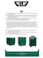
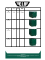
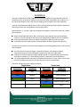
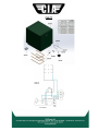
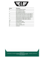
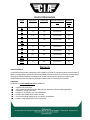
Safety ● The stationary oven sold with this manual should not be used for any purpose other than that for which it was designed. ● Before operating the oven it is advised that this user manual is read and understood by all users. Accidents and potential risks can be reduced by a thorough knowledge of the ovens operations and ideal working environment. ● It is important that the manual is kept in a tidy condition for any future reference, if a manual is misplaced or damaged, a replacement can be obtained from CIA Ovens. ● Do not damage or remove the safety and rating labels from the oven All mineral coated electrodes begin absorbing moisture once they are unpacked. Welding with moist electrodes leads to increase arc spatter, undercutting and poor slag removal. Other side effects include porosity, underbead cracking and generally low grade welds. The range of ovens provides facilities for every application where quality welds are required. NOTE: ELECTRODES MUST ALWAYS be removed from their wrappers or packets prior to heating. Failure to do so will result in an increased risk of fire and moisture not being carried off and being re-absorbed into the coating when the electrodes cool. ● In the event of danger such as fire or overheating it is important that the electrical supply be switched off at the first sight of danger ● Take great care when removing electrodes from the oven after heating, wear gloves and take care, the oven may still be very hot. ● Undergo all operations with general due care and attention Electrical Information To ensure that your CIA product is electrically safe, it is important to ensure that a suitably rated fuse is used in the plug when using the oven. By following simplistic electrical codes of practice such as Ohms law and the Power Triangle, determining the correct and appropriately rated fuse is used. Below is a explanation of these electrical theories: Oven Capacity Max Temp Power Output B1 50 KG 300 C 750Watt 150KG 300 C 1500Watt 110V, 240V 110-220V Single Phase B2 110V, 240V C1 150KG 400 C 2250 Watt 110V, 240V 110-220V Single Phase C2 150KG 500 C 3000 Watt 110V, 240V C2P 150KG 500 C 3000 Watt 110V, 240V C3 225KG 400 C 4700 Watt 380V 3 Phase C6 450KG 400C 9400 Watt 380V 3 Phase C9 380V 3 Phase 650KG 400C 13500 Watt MEC1 300KG 300C 2500Watt 240V MEC2 405KG 300C 5100Watt 380V 3 Phase Installation The Oven is shipped in a durable cardboard box to provide protection during shipment, wherever possible try to re-use the box or dispose it in an environmentally responsible way. For ovens C3, C6, C9 a heavy duty wooden crate is also used for shipping, please dispose of the crate responsibly. Great care should be taken with the ovens location and operating environment, please consider the following to ensure your CIA Stationary Oven is located safely: Oven models C3, C6, C9, MEC1, MEC2 are equipped with eyebolts, use these to lift the oven into the desired location. ● Where possible place the oven on flat or level ground, avoid slanted, uneven and undulating surfaces, or any environment in which the oven could become unstable or fall over completely. ● Ensure the ovens power cable is not subject to high tension, always provide some slack ● Do not place the oven in places where it could be subject to draft or high levels of humidity. Once the oven is placed in its optimal location adhere to the following guidelines for an efficient and safe installation: ● Check that the mains electrical supply is suitable for the oven. The voltage and power requirements are given on the rating plate located next to the mains supply cable. ● Connection to the mains electrical supply should be made via an appropriately fused plug for a single phase installation, or a fused isolator switch for a permanent 3 phase installation. ● It is recommended that the earth lead is connected with provision for some `slack` so that, in the event of the cable coming under stress the earth wire is the last to be affected The colour coding of the mains supply is as follows: Single Phase T hree Phase Wire Colour Connection Wire Colour Connection Brown Live Brown Line Conductor 1 Blue Neutral Black Line Conductor 2 Green/Yellow Earth Grey Line Conductor 3 - - Blue Neutral (Where Fitted) - - Green/Yellow Earth Operating Instructions Stationary Ovens B1, B2, C1, C2, C2P Starting the oven: 1. 2. 3. 4. 5. Ensure the oven is sitting steadily Open the door and fill with desired quantity of electrodes & close door firmly using door catch Securely plug the oven into a suitable power source and switch on the supply Turn the oven on via the neon switch located on the front of the oven, the digital display will begin to flash in its startup procedure. The display will then indicate the ovens internal temperature. Changing the ovens target temperature: (except C2P) 1. 2. 3. 4. Press the ‘P’ key on the digital controller Use the UP arrow or DOWN arrow keys to adjust to desired temperature Confirm the new temperature by pressing the ‘P’ key After a period of inactivity the controller will return to show the internal temperature whilst heating up to the desired temperature. Stationary Oven C2P Changing the ovens target temperature (Normal mode conditions) This sequence allows the user to select a custom cycle comprising of a main set point-soak time-secondary set point 1. 2. 3. 4. 5. Ensure the controller is switched on and not running in standby mode, (press the ‘O’ride’ button to activate the controller) Press ‘P’ key and Pr.S1 will be displayed, use the UP and DOWN arrow keys to adjust set point 1 Press ‘P’ key to confirm, Pr.t.1 will be displayed, use the UP and DOWN keys to adjust the soak/dwell time (Hours/Minutes), Press ‘P’ key to confirm PrS.2 will be displayed, use the UP and DOWN arrow keys to adjust set point 2- ‘P’ Key to confirm At the end of the cycle the the oven will remain in the active set point (set point 2) until the oven is switched off or the delay timer programme ceases. Changing the ovens target temperature (Delayed Mode Conditions) When used in conjunction with normal mode, this sequence allows the user to select a specific day and time to automatically switch the oven on and complete a pre-set cycle. Setting the clock: 1. Press the ‘Set’ button, the display will show 0.00 with ‘’C’’ flashing to the right of the display 2. Press the ‘Day’ button until the black indicator shows the desired day (1-7) 3. Use the ‘HRS’ button to set the hours followed by the ‘Mins’ button to set the minutes 4. Press ‘Set’ button to confirm Now programme the controller to a desired sequence as explained in ‘normal mode conditions’ section. Setting Programme 1: 1. Press the ‘Set’ button on the delay timer and hold for 3 seconds until the display shows --/-- with ‘1’ flashing (indicating programme 1)- the day indicator will point to ‘Day 1’ 2. Set the ‘ON’ time required for day one using the ‘Hrs’ and ‘Mins’ buttons to set hour and minute time accordingly. 3. Press the ‘Set’ button briefly and the display will show --/-- with ‘INT’ appearing on the display, this now requires an ‘OFF’ point to be set 4. In order to trip the logic input on the controller to switch to the pre-programmed cycle, set the first ‘OFF’ point 1 minute after the ‘’ON’’ time 5. Press the ‘Set’ button briefly and the display will show --/-- and the ON time for programme 2 can be set 6. To set programmes for different days press the ‘day’ button and select the desired day-the display will show --/-- ready for programme 1 setting 7. Programmes for day 2-7 can be set in the same way as day 1. Once the programming is complete press the ‘Set’ button and hold for 3 seconds until the display returns to the correct time of day, the timer is now in its operating condition. Suspending Programmes Press and hold down the Set button for about 3 seconds until the first "ON" programme, day 1 is displayed. Press the Day button repeatedly until the day indicator points to the day on which you wish to suspend the ON / OFF time. Press the Set button repeatedly until the "ON" or "OFF" time of the programme you wish to suspend is displayed. Now press the O'ride button. A black "X" will appear indicating that both the "ON" and "OFF" times for this programme have been suspended until reinstatement by the user. There is no limit to the number of programmes you can suspend. To reinstate a suspended programme return to either the "ON" or "OFF" time of the programme which has been suspended and cancel the black "X" by pressing the O'ride button. The ON / OFF programme will now operate on the selected day. Reviewing The Programmes Press and hold down the Set button for about 3 seconds until the first programme "ON" time for day 1 is displayed. Press the Day button repeatedly until the day indicator points to the day to be reviewed after which brief pressing of the Set button will display each programme or unused setting in sequence for that day. At any point the setting may be altered, if required, by using the hour & minute buttons. To review another day press the Day button until the day indicator points to the required day and use the Set button to select programmes as before. Stationary Ovens MEC1, MEC2 Starting the oven: 1. Check the power supply connections 2. The ‘white’ pilot light confirms that the oven is on. 3. Set the desired temperature on thermo-regulator; electrodes can be loaded in the oven immediately 4. The ‘Green’ pilot light (labeled Resistenze) confirms that the oven is heating up to desired temperature. Stationary Ovens C3, C6, C9 Starting the oven: 1. Load the oven with the desired amount of electrodes 2. Ensure the door is fully shut 3. Check that the power connections are secure 4. Turn the oven on via the main switch and check for power 5. After 10 seconds the thermoregulators are able to be programmed to the desired conditions. Altering the temperature and time set-points: In cases where a custom programme is required, please follow the instructions below: a) ADJUSTMENT OF THE HEATING ELEMENTS CONTROL AND SAFETY THERMOREGULATOR (°C heating element) : press and release the key L1 : the L1 led starts flashing, 1SP is displayed for one second , then the value linked to the setpoint appears; press LEFT or RIGHT to change the value ; the new value and the return to normal mode can be saved; the same happens after 10 seconds of inactivity. Press 0/1 to return to normal mode without saving any value. b) ADJUSTMENT OF THE OVEN-ENVIRONMENT THERMOREGULATOR (°C oven- environment) at active “SET POINT” stage ( SP1 or SP2 ). Cycle SP1 (drying): pressing the “P” key (for 1 sec.max.) , the SP1 adjustment is activated; act on UP and DOWN and set the required temperature (400°C max.); enter by pressing the P” key (for max. 1 sec.) After 6 hours (the time is adjustable from MENU as per following description) you can go to: Cycle SP2 (keeping): pressing the “P” key (for 1 sec.max.), the SP2 adjustment is activated; act on UP and DOWN set the required temperature (200°C max.); enter by pressing the “P” key (for 1 second max.) During the programming time checking is halted c) ADJUSTMENT OF THE OVEN-ENVIRONMENT THERMOREGULATOR (°C oven- environment) at inactive “SET-POINT” stage ( SP1 – SP2 ): The programming menu is activated pressing on “P” key for more than 2 seconds. Through UP and DOWN keys, select ‘’OPER’’ and confirm with the ‘’P’’ key. Select by UP/DOWN and choose “SP2”, enter by pressing “P”, 120° (or last programming) appears, select by UP/DOWN until the required value is achieved, enter by pressing “P” key. ( The thermoregulator gets back to start, whether no change is done in 20 seconds) Drying Time Programming (T Lasting) The programming menu is activated pressing on “P” key for more than 2 seconds . Through UP & DOWN keys, select ‘’OPER’’ and confirm with the ‘’P’’ key. ‘’ SP” appears, select by UP /DOWN keys, “] REG” appears, press “P” and time last. appears, press “P” and 6.00 (last programming stated in hours, min.) appears, select by UP/DOWN keys, until the required value is achieved, enter by pressing “P” key. (The thermo regulator gets back to start, if no change is completed within 20 seconds). It is necessary to switch the oven off and switch it on again when you change the parameters to apply them. Operating Recommendations Re-drying Temperatures The temperature at which basic electrodes should be re-dried depends on the level of hydrogen considered permissible in the deposited weld. Recommended re- drying temperatures to reduce hydrogen content to various limits are as follows: Condition Re-Drying Temperature Typical Application 10/15ml H2/100 grams weld 150 Celsius-60 Minutes To resist HAZ cracking on highly restrained joints & thick mild steel sections 5/10ml H2/100 grams weld 250 Celsius-60 Minutes For high duty applications pressure vessels structural work e.g. BS 1501. BS 4360 Below 5ml H2/100 450 Celsius-60 Minutes Highly critical alloyed materials Note: It has been suggested that the presence of even the smallest amount of hydrogen can adversely affect lamellar tearing. Therefore where lamellar tearing is a problem re-drying at 450c for 60 minutes is often carried out. Prolonged Drying Periods Some fabricators who are concerned to obtain the highest possible radiographic standards of weld metal have developed a technique whereby, the electrodes, on completion of drying, remain in the oven at full temperature until they are required for use. The technique is very effective in providing thoroughly dry electrodes but may tend to decrease the strength of the coating. It is suggested, therefore, that the maximum drying period for various re-drying temperatures should be set as follows: Drying Temperature Maximum Period at Temperature 150 Celsius 72 Hours 250 Celsius 12 Hours 450 Celsius 2 Hours Recommended Re-Drying Conditions Group Size (mm) Condition Mild steel rutile electrodes (Fastex 5, Zodian Universal) 1.6-6.0 80 Celsius- 60 Minutes Stainless steel electrodes (e.g: Nicrex E347-16. Nicrex E308L-16, Nicrex E316L-16) 1.6-5.0 350 Celsius- 120 Minutes 2.5-5.0 NOT RECOMMENDED Cellulosic electrodes (e.g: Celtian) Maintenance Planning of routine maintenance is an essential part of ensuring your CIA Ovens product is kept in the best possible condition and to ensure continual, efficient operation. Always conduct maintenance when the oven is out of service. Always ensure that the power cable is in good condition, free from breakages or tearing. NOTE: Check that the oven is cool before commencing maintenance work. STATIONARY OVEN B1 Element Replacement 1.Switch off and disconnect the oven from the electrical mains supply. 2.Retain all screws, nuts etc. for re-assembly. 3.Turn the oven upside down and remove the six screws securing the control box. 4.Note the connections and remove nuts, washers and wires from the element terminals. 5.Remove the bottom shelf & release the p’clip securing the element. Remove the element. 6.Check the element/s for continuity. 7.Replace the faulty element. 8.Re-assemble in the reverse order Thermocouple Replacement 1. Complete steps 1-3 of B1 element replacement 2. Note connections for the thermocouple into the controller, and disconnect where necessary 3. Remove the outer back panel with the 4 screws at the rear of the oven 4. Remove the clip holding the thermocouple at the back of the inner chamber and remove the thermocouple 5. Replace the faulty thermocouple and reverse steps 4-1 to build the oven back up Digital Controller Replacement 1. Complete steps 1-3 of B1 element replacement 2. Carefully note the connections to the rear of the controller before disconnecting 3. Remove the two white plastic panel clips holding the controller to the fascia 4. Remove the faulty controller. 5. Replace with new controller and reverse steps 4-1 to build the oven back up STATIONARY OVEN B2, C1, C2, C2P Element removal 1.Switch off and disconnect the oven from the electrical mains supply. 2.Retain all screws, nuts etc. for re-assembly. 3.Remove the four screws securing the back panel. 4.Note the connections and remove the nuts, washers and wires from the element terminals. 5.Loosen the element retaining clips on the top and bottom shelves and slide the elements out of the oven. 6.Check the elements for continuity. 7.Replace the faulty element/s. 8.Re-assemble in the reverse order. Thermocouple Replacement 1. Switch off and disconnect the oven from the electrical mains supply. 2. Retain all screws, nuts etc. for re-assembly. 3. Turn the oven upside down and remove the six screws securing the control box. 4. Note connections for the thermocouple into the controller, and disconnect where necessary 5. Remove the outer back panel with the 4 screws at the rear of the oven 6. Remove the nut holding the thermocouple at the back of the inner chamber and remove the thermocouple 7. Replace the faulty thermocouple and reverse steps 4-1 to build the oven back up Digital Controller Replacement 1. Complete steps 1-3 of thermocouple replacement 2. Carefully note the connections to the rear of the controller before disconnecting 3. Remove the two white plastic panel clips holding the controller to the fascia 4. Remove the faulty controller. 5. Replace with new controller and reverse steps 4-1 to build the oven back up STATIONARY OVENS C3, C6, C9 Element replacement 1. Open the oven door and remove the electrode trays. 2. Remove the metal hat shaped cover located on the rear of the oven. 3. Disconnect the faulty heating element and replace with a new one having the same properties and sizes. 4. Fit the new heating element. 5. Reassemble the bottom cover on the rear of the oven. 6. Place the electrode trays in the oven chamber 7. Switch on the oven main power switch for few minutes to eliminate any possible humidity residual on the new heating element. 8. Switch off the oven and let the heating elements cool. 9. The oven is now ready for operation. Extraordinary maintenance Periodically check the quality and connection of electrical wires and components, and replace where necessary. In the case of any further problem, please contact your dealer or directly to CIA Ovens who are on hand to help resolve your problem. STATIONARY OVENS MEC1, MEC2 Element replacement 1. Disconnect the oven from the power source. 2. Open the door and remove the tray from the oven. 3. Remove the metal hat shaped cover located on the rear of the oven. 4. Disconnect the electrical cable from the faulty heating element. 5. Fit the new heating element having the same properties and sizes and restore the right connections. 6. Install the metal hat shaped cover electrical heating element connections. 7. Place the electrode trays in the oven chamber. 8. Switch on the oven main power switch for few minutes, then switch it off and let the heating elements cool and let them cool for about 15 minutes. This stabilizes the new heating element so it will last longer. 9. The oven is now ready for operation CIA B1 CIA B2 CIA C1 CIA C2 CIA C2P CIA C3, C6, C9 MPS Main Power Switch 3x16/3x25/3x32A ThE Element Thermoregulator ThAT Air temp Thermoregulator IND1 Green ‘’ON’’ signal lamp IND2 White ‘’CONNECTION’’ signal lamp HERCS Element(s) remote control switch HE1HE2HE3 Heating Elements 230V 1500W x C3C6C9Fm2/ 2750W x FmFm1/ 1300W x C100 C200C400D TR 220380/24V Transformer F10F20F30 Fuses 16A (C3)20A (C6)32A (C9) F4050 Fuse 2A DMS Door Micro Switch CIA MEC1, MEC2 Item Part Number Item Part Number Neons High Temp Elements Neon Indicator 110/240V 100.001 C2C2P Element 1500Watt 205.030 Neon Indicator 48/85V Chrome Bezel 100.002 Thermocouple Neon switch 240V 100.003 Thermocouple Type K 300.004 Digital Controllers Solid State Relay B1, B2, C1 Digital Controller 101.050 Solid State Relay (90240V 332Vdc) 40Amp 300.019 C2 Digital Controller 101.055 Door Parts C2P Digital Controller 101.060 Door Catch 600.007 Stationary Oven Elements Door Knob (M6 Black Moulded Knob) 600.008 110V, 750Watt, 940mmx 6.5ø element 202.020 Door Seal Kit (Glass fibre tape + rivets) 600.009 240V 750W, 940mmx6.5ø element 202.021 Thermostats Quiver Elements Thermostat Kit (120c) 700.120 110240V Dual voltage element (P16) 203.001 Thermostat Kit (200c) 700.200 24V150Watt 6.35ø element 203.002 Thermostat Kit (320c) 700.320 80V200Watt 6.35ø element 203.003 Capacitors 110V150Watt 6.35ø element 203.004 Capacitor (48/85V versions only) 999.000 240V150Watt 6.35ø element 203.008 Data Logger Kits 48/85V300Watt Element P8P15 203.005 Data Logger 999.001 110V300Watt Element P8P15 203.006 Thermal Cut Out's 240V300Watt Element P8P15 203.007 Thermal Cut out (2448/85V Quiver only) 999.002 Dual voltage quiver element 110/240V 150W 203.009 Thermometers 85V275Watt 100x100 Square Element 204.060 0250 Deg Thermometer 999.003 110V275Watt 100x100 Square Element 204.061 32500 Deg Thermometer 999.004 240V275Watt 100x100 Square Element 204.062 Voltage Selectors Voltage Selector Switch 999.005 Programmable Timer 7 Day Programmable Timer C2P 999.006 Useful Information Model Power (kW) Capacity Kg Internal dimensions (mm) Shipping Weight Kg B1 0.75 50 250x480x250 19 B2 1.5 136 470x470x480 40 C1 2.25 136 470x470x480 40 C2 3 136 470x470x480 65 C2P 3 136 470x470x480 65 C3 4.7 225 740x530x470 150 C6 9.4 450 740x530x890 215 C9 13.5 650 740x530x1330 280 MEC1 2.5 300 650x520x550 95 MEC2 5.1 405 650x520x810 117 Warranty General conditions CIA guarantees the product mentioned in this manual for a period of 12 (twelve) months from the date of delivery. The warranty is valid for the above mentioned period and only for the parts that will have defect of design or defective material. CIA will give you further instructions for repairing or replacing the complained parts, free of charge. Any transport expenses will be covered by the customer. Limitations CIA Ovens Ltd is not and will not be responsible for: ● ● ● ● ● ● ● Improper use of the oven A use against the national and/or International regulations in force (where applicable) Improper or wrong connection Improper or insufficient care and maintenance Unauthorized modifications and/or services Use of non-original spare parts or non-specific components Partial or total Inobservance of the instructions