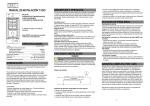
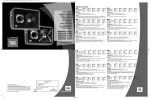
1
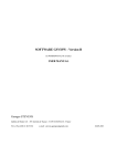
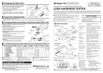
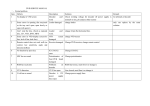
Safety ● The portable oven sold with this manual should not be used for any purpose other than that for which it was designed. ● Before operating the oven it is advised that this user manual is read and understood by all users. Accidents and potential risks can be reduced by a thorough knowledge of the ovens operations and ideal working environment. ● It is important that the manual is kept in a tidy condition for any future reference, if a manual is misplaced or damaged, a replacement can be obtained from CIA Ovens. ● Do not damage or remove the safety and rating labels from the oven All mineral coated electrodes begin absorbing moisture once they are unpacked. Welding with moist electrodes leads to increase arc spatter, undercutting and poor slag removal. Other side effects include porosity, underbead cracking and generally low grade welds. The range of ovens provides facilities for every application where quality welds are required. NOTE: ELECTRODES MUST ALWAYS be removed from their wrappers or packets prior to heating. Failure to do so will result in an increased risk of fire and moisture not being carried off and being re-absorbed into the coating when the electrodes cool. ● In the event of danger such as fire or overheating it is important that the electrical supply be switched off at the first sight of danger ● Take great care when removing electrodes from the oven after heating, wear gloves and take care, the oven may still be very hot. ● Undergo all operations with general due care and attention Electrical Information To ensure that your CIA product is electrically safe, it is important to ensure that a suitably rated fuse is used in the plug when using the oven. By following simplistic electrical codes of practice such as Ohms law and the Power Triangle, determining the correct and appropriately rated fuse is used. Below is a explanation of these electrical theories: Oven Capacity Max Temp Power Output P7 9 KG 110 ° C 150Watt 7KG 190 ° C 275Watt 24V, 48-85V, 110V, 240V 110-220V Single Phase P8 48-85V, 110V, 240V P8M2 9KG 48/85V, 110V, 240V 190 ° C 275 Watt 110-220V Single Phase P15 48-85V, 110V, 240V 11KG 200 ° C 275 Watt P15M2 15KG 24V, 48-85V, 110V, 240V 190 ° C 275 Watt P16 110V/240V Dual Voltage 14KG 320 ° C 300 Watt Installation The Oven is shipped in a durable cardboard box to provide protection during shipment, wherever possible try to re-use the box or dispose it in an environmentally responsible way. Great care should be taken with the ovens location and operating environment, please consider the following to ensure your CIA Portable Oven is located safely: ● Where possible place the oven on flat or level ground, avoid slanted, uneven and undulating surfaces, or any environment in which the oven could become unstable or fall over completely. ● Ensure the ovens power cable is not subject to high tension, always provide some slack ● Do not place the oven in places where it could be subject to draft or high levels of humidity. Once the oven is placed in its optimal location adhere to the following guidelines for an efficient and safe installation: ● Check that the mains electrical supply is suitable for the oven. The voltage and power requirements are given on the rating plate located next to the mains supply cable. ● Connection to the mains electrical supply should be made via an appropriately fused plug for a portable oven. ● It is recommended that the earth lead is connected with provision for some `slack` so that, in the event of the cable coming under stress the earth wire is the last to be affected The colour coding of the mains supply is as follows Single Phase Wire Colour Connection Brown Live Blue Neutral Green/Yellow Earth Operating Instructions Portable Quiver P7 Starting the oven: 1. 2. 3. 4. Ensure the oven is sitting steadily Open the door and fill with desired quantity of electrodes & close door firmly Securely plug the oven into a suitable power source and switch on the supply The oven will now start to heat up to maximum temperature, it may be necessary to turn on the neon switch (where fitted) Portable Rod Oven P8, P8M2, P15, P15M2 Starting the oven: 1. 2. 3. Complete steps 1-3 from P7 startup instructions Turn the thermostat bezel to the desired temperature, a ‘click’ can be heard as the thermostat is switched on. The oven will now heat up to its target temperature set by the operator, the neon indicator will go out when the oven reaches its set target. Portable Rod Oven P16 Starting the oven: 1. 2. 3. 4. Ensure that the voltage selector switch is set to the desired operating voltage. Complete steps 1-3 of P7 startup instructions. Turn the thermostat bezel to the desired temperature, a ‘click’ can be heard as the thermostat is switched on. The oven will now heat up to its target temperature set by the operator, the neon indicator will go out when the oven reaches its set target. Operating Recommendations Electrode Stabilization The temperature at which basic electrodes should be re-dried depends on the level of hydrogen considered permissible in the deposited weld. Recommended re- drying temperatures to reduce hydrogen content to various limits are as follows: Type Temperature after Opening Typical Reconditioning environment Cellulose 40∘C-50∘C Not Recommended Iron Powder M.S 40∘C-50∘C 80-100∘C 30 Minutes Titania 40∘C-50∘C 80-100∘C 30 Minutes Low Hydrogen/ Low Hydrogen High Tensile 120∘C-150∘C 80-100∘C 90 Minutes Stainless 120∘C-150∘C 80-100∘C 90 Minutes Inconel,Monel, Hard surfacing 65∘C-95∘C 80-100∘C 30 Minutes Brasses, Bronzes 65∘C-95∘C Not Recommended Note: It has been suggested that the presence of even the smallest amount of hydrogen can adversely affect lamellar tearing. Therefore where lamellar tearing is a problem re-drying at 450c for 60 minutes is often carried out. Prolonged Drying Periods Some fabricators who are concerned to obtain the highest possible radiographic standards of weld metal have developed a technique whereby, the electrodes, on completion of drying, remain in the oven at full temperature until they are required for use. The technique is very effective in providing thoroughly dry electrodes but may tend to decrease the strength of the coating. It is suggested, therefore, that the maximum drying period for various re-drying temperatures should be set as follows: Drying Temperature Maximum Period at Temperature 150 Celsius 72 Hours 250 Celsius 12 Hours 450 Celsius 2 Hours Maintenance Planning of routine maintenance is an essential part of ensuring your CIA Ovens product is kept in the best possible condition and to ensure continual, efficient operation. Always conduct maintenance when the oven is out of service. Always ensure that the power cable is in good condition, free from breakages or tearing. NOTE: Check that the oven is cool before commencing maintenance work. HEATED QUIVER P7 Element and Switch Replacement 1.Switch off and isolate the quiver from the mains supply. 2.Retain all screws. 3.Turn the quiver and remove the four screws securing the base panel. 4.Remove the two screws from the element anchor. 5.Remove the element and replace as necessary. 6.To replace switch, note connections, remove leads from the terminals and replace the switch. 7.Reassemble in the reverse order. HEATED INSULATED QUIVER P8, P8M2, P15 & P15M2 Thermostat replacement 1.Switch off and disconnect the oven from the electrical mains supply. 2.Retain all screws, nuts etc. for re-assembly. 3.Stand the oven on its front edge and remove the four screws securing the base panel. 4.Remove the thermostat knob & the bezel retaining screws. 5.Note the electrical connections before removing any terminations. 6.Remove the wires from their terminals. 7.Remove the thermostat. 8.Re-assemble in the reverse order. Element replacement (P8 & P15) 1.Carry out paragraphs 1 - 4 of thermostat replacement. 2.Note the position of the element terminations and remove the Fastons. 3.Remove the two screws retaining the Element assembly. 4.Remove the element assembly and replace with new. 5.Reassemble in the reverse order Element replacement (P8M2 & P15M2) 1.Carry out paragraphs 1 - 4 of thermostat replacement. 2.Note the position of the element terminations and remove the Fastons. 3.Un tighten the nut retaining the heat sink and element assembly on the back of the inner body. 4. Remove the heatsink clear of the element 5.Remove the element assembly and replace with new. 6.Reassemble in the reverse order. PORTABLE DRYING ROD OVEN P16 Thermostat replacement 1.Switch off and disconnect the oven from the electrical mains supply. 2.Retain all screws, nuts etc. for re-assembly. 3.Stand the oven on its front edge and remove the four screws securing the base panel. 4.Remove the thermostat knob & the bezel retaining screws. 5.Note the electrical connections before removing any terminations. 6.Remove the wires from their terminals. 7.Remove the thermostat. 8.Re-assemble in the reverse order. Element replacement 1.Carry out paragraphs 1 - 4 of thermostat replacement. 2.Note the position of the element terminations and remove the nuts and washers. 3.Remove the two screws retaining the Element assembly. 4.Remove the element assembly and replace with new. 5.Reassemble in the reverse order . Extraordinary maintenance Periodically check the quality and connection of electrical wires and components, and replace where necessary. In the case of any further problem, please contact your dealer or directly to CIA Ovens who are on hand to help resolve your problem. CIA P7 CIA P8 48/85V Versions are fitted with a capacitor between the thermostat terminals CIA P8M2 48/85V Versions are fitted with a capacitor between the thermostat terminals CIA P15 48/85V Versions are fitted with a capacitor between the thermostat terminals CIA P15M2 48/85V Versions are fitted with a capacitor between the thermostat terminals CIA P16 Item Part Number Item Part Number Neons High Temp Elements Neon Indicator 110/240V 100.001 C2C2P Element 1500Watt 205.030 Neon Indicator 48/85V Chrome Bezel 100.002 Thermocouple Neon switch 240V 100.003 Thermocouple Type K 300.004 Digital Controllers Solid State Relay B1, B2, C1 Digital Controller 101.050 Solid State Relay (90240V 332Vdc) 40Amp 300.019 C2 Digital Controller 101.055 Door Parts C2P Digital Controller 101.060 Door Catch 600.007 Stationary Oven Elements Door Knob (M6 Black Moulded Knob) 600.008 110V, 750Watt, 940mmx 6.5ø element 202.020 Door Seal Kit (Glass fibre tape + rivets) 600.009 240V 750W, 940mmx6.5ø element 202.021 Thermostats Quiver Elements Thermostat Kit (120c) 700.120 110240V Dual voltage element (P16) 203.001 Thermostat Kit (200c) 700.200 24V150Watt 6.35ø element 203.002 Thermostat Kit (320c) 700.320 80V200Watt 6.35ø element 203.003 Capacitors 110V150Watt 6.35ø element 203.004 Capacitor (48/85V versions only) 999.000 240V150Watt 6.35ø element 203.008 Data Logger Kits 48/85V300Watt Element P8P15 203.005 Data Logger 999.001 110V300Watt Element P8P15 203.006 Thermal Cut Out's 240V300Watt Element P8P15 203.007 Thermal Cut out (2448/85V Quiver only) 999.002 Dual voltage quiver element 110/240V 150W 203.009 Thermometers 85V275Watt 100x100 Square Element 204.060 0250 Deg Thermometer 999.003 110V275Watt 100x100 Square Element 204.061 32500 Deg Thermometer 999.004 240V275Watt 100x100 Square Element 204.062 Voltage Selectors Voltage Selector Switch 999.005 Useful Information Model Power (kW) Capacity Kg Internal dimensions (mm) Shipping Weight Kg P7 0.15 9 121x115x460 3.3 P8 0.3 7 73x73x450 6 P8M2 0.275 7 73x73x450 5 P15 0.3 11 105x105x450 7 P15M2 0.275 15 105x105x450 7 P16 0.3 14 121x115x460 8 Warranty General conditions CIA guarantees the product mentioned in this manual for a period of 12 (twelve) months from the date of delivery. The warranty is valid for the above mentioned period and only for the parts that will have defect of design or defective material. CIA will give you further instructions for repairing or replacing the complained parts, free of charge. Any transport expenses will be covered by the customer. Limitations CIA Ovens Ltd is not and will not be responsible for: ● ● ● ● ● ● ● Improper use of the oven A use against the national and/or International regulations in force (where applicable) Improper or wrong connection Improper or insufficient care and maintenance Unauthorized modifications and/or services Use of non-original spare parts or non-specific components Partial or total Inobservance of the instructions