1
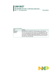
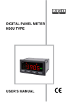
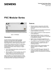
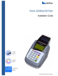
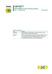
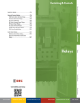
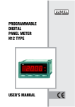
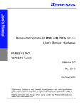
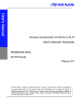
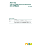
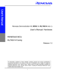
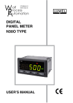
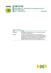
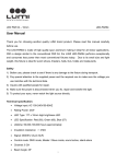
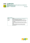
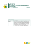
AN11617 SSL6203TW 120 V 12 W linear LED driver Rev. 1 — 13 April 2015 Application note Document information Info Content Keywords SSL6203TW, TRIAC dimmable, linear LED driver, incandescent dimming curve Abstract This application note is a guide for the design and layout of a linear LED driver used in dimmable Solid-State Lighting (SSL) LED lighting. This document describes the theory of linear LED drivers, the benefit of SSL6203TW patented structure (81644813; US 20140125235 A1; US 20130257282 A1; CN103384431A; EP2645816A1). It also describes the circuit design to get good dimmer compatibility and incandescent dimming curve. AN11617 NXP Semiconductors SSL6203TW 120 V 12 W linear LED driver Revision history Rev Date Description v.1 20150413 first issue Contact information For more information, please visit: http://www.nxp.com For sales office addresses, please send an email to: [email protected] AN11617 Application note All information provided in this document is subject to legal disclaimers. Rev. 1 — 13 April 2015 © NXP Semiconductors N.V. 2015. All rights reserved. 2 of 24 AN11617 NXP Semiconductors SSL6203TW 120 V 12 W linear LED driver 1. Introduction Linear LED drivers are a relatively new way of driving LEDs. The driver connects high-voltage (HV) LEDs directly to the mains when sufficient voltage is available. More HV LEDs are connected in series as more mains voltage is available. To optimize LED utilization and achieve a balanced optical and thermal lamp design, the NXP Semiconductors linear LED driver employs switches. A linear LED driver enables very small form factor LED lamps because it incorporates fewer components than traditional switched-mode LED drivers. The linear LED driver is small enough to be integrated on the LED plate. Making performance compromises and removing components can further reduce the driver size. AN11617 Application note All information provided in this document is subject to legal disclaimers. Rev. 1 — 13 April 2015 © NXP Semiconductors N.V. 2015. All rights reserved. 3 of 24 AN11617 NXP Semiconductors SSL6203TW 120 V 12 W linear LED driver 2. High-voltage linear driver Depending on the instantaneous rectified mains voltage (Vrect), linear LED drivers connect one or multiple HV LED strings to the mains. Figure 1 shows the concept of a conventional linear LED driver. When the mains voltage is high enough to turn on one LED string (Vrect > VLED), the driving current starts flowing through that LED. Similarly, if the mains voltage is high enough, LEDs 2 and 3 are turned on. When the mains voltage decreases, LED3 is turned off when Vrect < 3 * VLED, LED2 when Vrect < 2 * VLED. Finally, when Vrect < VLED, LED1 is turned off. A significant drawback is that LED1 remains turned on for a relatively long time, while LED3 is only turned on for a relatively short time. The impact on the application is that LED1 has both a higher average current and a higher temperature, leading to a lower efficacy and a lower lifetime. Simultaneously, LED3 is underutilized. So this system has a poor LED utilization. 9UHFW 9/(' 9/(' 9/(' 9UHFW ,/(' /(' /(' 9PDLQV ,/(' FRQWURO /(' FRQWURO ,/(' FRQWURO 4 a. Circuit Fig 1. 4 DDD DDD b. Waveform Conventional linear LED driver AN11617 Application note All information provided in this document is subject to legal disclaimers. Rev. 1 — 13 April 2015 © NXP Semiconductors N.V. 2015. All rights reserved. 4 of 24 AN11617 NXP Semiconductors SSL6203TW 120 V 12 W linear LED driver 2.1 Improved LED utilization To overcome the problem that conventional linear drivers have, the NXP Semiconductors linear LED driver uses switches. Switches are added to disable LEDs 1 and 2. Figure 2 shows this concept. In the first quarter of the mains cycle, LED1, LED2, and LED3 turn on in the same way as with the conventional LED driver. However, in the second quarter a switch is used to turn off LED1 when Vrect < 3 * VLED. A second switch is used to turn off LED2 when Vrect < 2 * VLED. The result is that the on-times of the three LEDs have now become similar, as have their efficacy, light output, and temperature. It simplifies the design and so reduces the overall system cost. 9UHFW 9/(' 9/(' 9/(' 9UHFW ,/(' ,/(' 9PDLQV FRQWURO ,/(' FRQWURO FRQWURO 4 a. Circuit Fig 2. 4 DDD DDD b. Waveform NXP Semiconductors linear LED driver AN11617 Application note All information provided in this document is subject to legal disclaimers. Rev. 1 — 13 April 2015 © NXP Semiconductors N.V. 2015. All rights reserved. 5 of 24 AN11617 NXP Semiconductors SSL6203TW 120 V 12 W linear LED driver 2.2 Improved quality of light While the system shown in Figure 2 has balanced LED utilization, it still has 100 % light ripple at 100 Hz. The LEDs cannot be driven when Vrect < VLED. So, around the zero crossings of the mains voltage, all LEDs are off. The result is a poor quality of light. To solve this issue, capacitors can be placed in parallel with the LEDs. Figure 3 shows this concept. This solution causes the LED currents to be averaged. It prevents that the LEDs turn off completely around the mains zero crossings. The remaining current ripple is a design parameter. Choosing a proper capacitance value can set this parameter. To prevent that the capacitors are discharged at low mains voltages or when the switches are used, blocking diodes must be placed as well. An additional advantage of using the electrolytic capacitors is that the LEDs are driven at a lower current, which means the efficacy of the LEDs is slightly higher. The NXP Semiconductors linear LED driver IC works both with and without capacitors being added to the system. 9PDLQV FRQWURO FRQWURO FRQWURO DDD Fig 3. AN11617 Application note NXP Semiconductors linear LED driver with electrolytic capacitors All information provided in this document is subject to legal disclaimers. Rev. 1 — 13 April 2015 © NXP Semiconductors N.V. 2015. All rights reserved. 6 of 24 AN11617 NXP Semiconductors SSL6203TW 120 V 12 W linear LED driver 2.3 Improved thermal performance The mismatch between the cumulative LED voltage and the mains voltage mainly determines the efficiency of linear LED drivers (see Figure 4). Because the same current is drawn from the mains regardless of how many HV LEDs are active, the dissipation in the LED driver varies with the difference between the cumulative LED voltage and the instantaneous mains voltage. 9ROWDJH 9 9OHG 5HODWLYHWLPHIUDFWLRQ 5HODWLYHWLPHIUDFWLRQ 3RZHUORVV : DDD Fig 4. Mains voltage compared to the cumulative LED voltage and resulting dissipation in the LED driver To prevent that the IC becomes a hot spot in the application, heat reduction resistors are added. These resistors allow a 40 % reduction of the dissipation in the LED driver IC. The resistors can be placed at a distance from the IC, so they provide a way for the dissipation to spread across the application. Figure 5 shows the concept of the heat reduction resistors. Each LED current source is divided in an A and a B branch. An external resistor is placed in the B branch. When a string has turned on, current initially flows mostly through branch A. As the mains voltage increases, the mismatch between the cumulative LED voltage and the mains voltage increases as well. This additional voltage allows current to start flowing through the B branch. The transistors in the A and B branch are biased so that the transfer of current occurs automatically. AN11617 Application note All information provided in this document is subject to legal disclaimers. Rev. 1 — 13 April 2015 © NXP Semiconductors N.V. 2015. All rights reserved. 7 of 24 AN11617 NXP Semiconductors SSL6203TW 120 V 12 W linear LED driver 9UHFW9/(' 9UHFW9/(' 5+[ 675[$ 675[% 9GG 9RIIVHW 9GG ,675[$ ,675[% /(' FXUUHQW VRXUFH DDD Fig 5. Heat reduction resistor For Vrect = 120 V, Pin = 12 W, and IHVLCS = 120 mA, a good value for the heat reduction resistor is: RHx = 350 . AN11617 Application note All information provided in this document is subject to legal disclaimers. Rev. 1 — 13 April 2015 © NXP Semiconductors N.V. 2015. All rights reserved. 8 of 24 AN11617 NXP Semiconductors SSL6203TW 120 V 12 W linear LED driver 2.4 Limiting maximum dissipation and design for typical operation Linear LED drivers normally have relatively poor line regulation because for higher mains voltages, the on-time of the LEDs increases. The result is a higher average LED current and a higher output power. Figure 6 shows this effect. The thermal design of the lamp must be dimensioned for the highest power level, which is for Vmains = 132 V. Dimensioning in this way is undesirable because Vmains = 132 V is not the typical operating condition. DDD 9UHFW P9/('V 9 WLPHV a. Vrect = 108 V (AC) DDD 9UHFW P9/('V 9 WLPHV b. Vrect = 132 V (AC) Fig 6. AN11617 Application note Mains waveform and cumulative LED All information provided in this document is subject to legal disclaimers. Rev. 1 — 13 April 2015 © NXP Semiconductors N.V. 2015. All rights reserved. 9 of 24 AN11617 NXP Semiconductors SSL6203TW 120 V 12 W linear LED driver To allow the design for the typical operating condition of Vmains = 120 V, the LED driving current is reduced when Vmains > 120 V. To achieve this LED driving current limitation, the feedback through the OV pin of the IC is used. The OV feedback limits the dissipation of the lamp for higher mains voltages (See Figure 7). Fig 7. OV feedback used to limit the dissipation of the lamp for Vmains > 120 V At what voltage the OV feedback starts, can be configured using Zener diode ZOV. Resistor ROV then sets the strength of the feedback. Figure 11 shows the connection of ZOV and ROV. Typical values for ZOV and ROV are: • ZOV = 20 V • ROV = 360 k AN11617 Application note All information provided in this document is subject to legal disclaimers. Rev. 1 — 13 April 2015 © NXP Semiconductors N.V. 2015. All rights reserved. 10 of 24 AN11617 NXP Semiconductors SSL6203TW 120 V 12 W linear LED driver 2.5 Mains surge protection The maximum rated voltage of the HV pins of the SSL6203TW at room temperature is 350 V. As the SSL6203TW targets the US market, the application has to withstand a 2.5 kV ring wave test, superimposed on a peak mains voltage of V peak = 132 2 = 187 V . As the power to be dissipated during the surge test is too high for the SSL6203TW to handle, external protections are required to protect the IC. Figure 8 shows a proposed protection circuit. A large TVS is used as a primary protection. A small surge resistor creates some voltage drop for the secondary protection TVS. Finally, a small capacitor limits the dV/dt and the maximum voltage swing on the rectified mains. Place this capacitor as close to the IC as possible. A Metal-Oxide Varistor (MOV) can also replace the large input TVS. 796 N: 9PDLQV 796 : Q) DDD Fig 8. AN11617 Application note Proposed input protection circuit All information provided in this document is subject to legal disclaimers. Rev. 1 — 13 April 2015 © NXP Semiconductors N.V. 2015. All rights reserved. 11 of 24 AN11617 NXP Semiconductors SSL6203TW 120 V 12 W linear LED driver 3. Applications The NXP Semiconductors linear driver can be used with a mains voltage of 120 V (RMS). Three applications with varying performance levels are suggested here. All three solutions conform to standard mains surge and EMI requirements. A 10 nF HV input capacitor is required from RECT to GND to ensure correct operation of the linear driver IC. The NXP Semiconductors linear LED driver incorporates a smart bleeder for increased dimmer compatibility. This bleeder is only activated when insufficient mains voltage is available to support activation of an HV LED. A single resistor RBLEED sets the bleeder current IHVBCS for each of the solutions. This resistor is connected between the IC voltage supply pins VDD1/2 and the bleeder current reference pin BLEED. To generate the bleeder current IHVBCS 1000 II(BLEED), the reference current flowing into the BLEED pin is multiplied by approximately 1000. I HVBCS I I BLEED + 2.5 mA 1000 45 mA (1) The bleeder current must be 45 mA, as indicated by Equation 1. The bleeder current IHVBCS is sunk from the RECT pin. For more information about how the bleeder current is calculated, see the SSL6203TW data sheet. The resistor value that sets the bleeder reference current II(BLEED) can be calculated with Equation 2: 12.5 R BLEED = ----------------------- I I BLEED (2) Figure 9 shows the phase-cut dimming waveforms of total input current (magenta), IHVBCS (yellow), mains voltage (blue) and STR3A (green). When the dimmer is off (i.e. when the mains voltage is zero), the bleeder only discharges the capacitive current from the dimmer. At the end of the mains cycle, when insufficient mains voltage is available to turn on one HV LED, the bleeder becomes fully active. AN11617 Application note All information provided in this document is subject to legal disclaimers. Rev. 1 — 13 April 2015 © NXP Semiconductors N.V. 2015. All rights reserved. 12 of 24 AN11617 NXP Semiconductors SSL6203TW 120 V 12 W linear LED driver (1) Magenta = Input current (2) Yellow = IHVBCS (3) Blue = Mains voltage (4) Green = STRA3A Fig 9. Phase-cut dimming waveforms showing when the bleeder is active When insufficient bleeder current is set, shimmer or flutter can occur at certain dimmer angles for a phase-cut dimmer. Figure 10 show example waveforms of a dimmer showing this behavior. The discontinuity in the mains voltage indicates that the dimmer turns off because of insufficient bleeder current. As in some cycles the dimmer works properly and in other cycles it does not, shimmer or flutter can be observed. (1) Magenta = Input current (2) Yellow = IHVBCS (3) Blue = Mains voltage (4) Green = STRA3A Fig 10. Shimmer or flutter can occur when an insufficient bleeder current is set AN11617 Application note All information provided in this document is subject to legal disclaimers. Rev. 1 — 13 April 2015 © NXP Semiconductors N.V. 2015. All rights reserved. 13 of 24 AN11617 NXP Semiconductors SSL6203TW 120 V 12 W linear LED driver 3.1 High-performance dimmable application Figure 11 shows the high performance phase-cut dimmable application. ' 5685*( 5(&7 QF 5/ '%5,'*( IXVH *1' PDLQV 029796 796 %/((' 5/(' &'9'7 9'' 9'' &/ 5/(' &9'' /(' &/(' 675% ' QF 675$ 5 29 & /(' QF 675% 5+ ' QF 5 QF /(' 5+ &/(' /*1' & 66/7: =/(' 5 5%/((' 675$ (3$' =29 & /(' 675$ QF 5+$ 675% 5+% 529 DDD Fig 11. High-performance dimming application schematic This application features a near-incandescent lamp dimming curve and a high quality of light through placement of capacitors C1, C2. and C3 in parallel with the LEDs. To prevent that capacitors C1, C2, and C3 are discharged at low mains voltages and when the switches are used, blocking diodes D1, D2. and D3 are required. Figure 12 shows the waveforms of the RECT, STR3A, and C3 ripple current when a capacitor of 100 F is used. The remaining current ripple for this configuration is 30 %. AN11617 Application note All information provided in this document is subject to legal disclaimers. Rev. 1 — 13 April 2015 © NXP Semiconductors N.V. 2015. All rights reserved. 14 of 24 AN11617 NXP Semiconductors SSL6203TW 120 V 12 W linear LED driver (1) Green = Mains current (2) Blue = STRA3A (3) Yellow = Output ripple Fig 12. Ripple current of capacitor 3 (yellow) for a capacitance of 100 F Providing a reference current II(LED) to the LED pin of the IC sets the LED current IHVLCS. To obtain the LED driving current, i.e. ILED 1000 (II(LED) + 17 A), this reference current and the internal reference current of about 17 A are multiplied by approximately 1000. For the high-performance application, the RLED1, RLED2, ZLED, CLED1, CLED2 network generates the Iref(LED). This network provides a reference current that scales with the average mains voltage. When phase-cut dimming is used, the average mains voltage decreases. Iref follows and decreases the LED driving current. The result is a near-incandescent dimming curve (see Figure 13). AN11617 Application note All information provided in this document is subject to legal disclaimers. Rev. 1 — 13 April 2015 © NXP Semiconductors N.V. 2015. All rights reserved. 15 of 24 AN11617 NXP Semiconductors SSL6203TW 120 V 12 W linear LED driver DDD ,/(' 'LPPHUDQJOH (1) Upper NEMA limit (2) Incandescent (3) SSL6203TW (4) Lower NEMA limit Fig 13. Dimming curve of the high-performance dimmable application To trigger phase-cut dimmers correctly, an RC latch (components RL and CL) between the RECT and GND nodes is required. Typically, RL = 1 k and CL = 68 nF. AN11617 Application note All information provided in this document is subject to legal disclaimers. Rev. 1 — 13 April 2015 © NXP Semiconductors N.V. 2015. All rights reserved. 16 of 24 AN11617 NXP Semiconductors SSL6203TW 120 V 12 W linear LED driver 3.2 Low-cost dimmable application Figure 14 shows the low-cost phase-cut dimmable application schematic. The main differences with the high-performance dimmable application are that the capacitors to improve light quality have been omitted and that II(LED) is now generated with a single resistor to the IC voltage supply VDD. 5685*( 5(&7 QF 5/ '%5,'*( IXVH *1' PDLQV 029 796 %/((' &'9'7 9'' 9'' &/ &9'' 5/(' /(' /(' 5%/((' 675$ 675% 5+ QF /(' 675$ QF 675% 5+ 66/7: /(' QF &/(' /*1' QF 29 (3$' =29 675$ QF 5+$ 675% 5+% 529 DDD Fig 14. Low-cost dimmable application schematic AN11617 Application note All information provided in this document is subject to legal disclaimers. Rev. 1 — 13 April 2015 © NXP Semiconductors N.V. 2015. All rights reserved. 17 of 24 AN11617 NXP Semiconductors SSL6203TW 120 V 12 W linear LED driver Figure 15 shows how the fixed II(LED) reference current changes the dimming curve of the linear LED driver, which is according to the NEMA standard. DDD ,/(' 'LPPHUDQJOH (1) Upper NEMA limit (2) Incandescent (3) SSL6203TW (4) Lower NEMA limit Fig 15. Low-cost dimmable application dimming curve The LED driving current IHVLCS can be estimated using Equation 3: I HVLCS I I LED + 17 A 1000 120 mA (3) The LED driving current must be 120 mA as indicated by Equation 3. The required value for RLED can be set using Equation 4: 11.25 R LED = ---------------- I I LED (4) Section 3.1 describes the setting of the bleeder current. AN11617 Application note All information provided in this document is subject to legal disclaimers. Rev. 1 — 13 April 2015 © NXP Semiconductors N.V. 2015. All rights reserved. 18 of 24 AN11617 NXP Semiconductors SSL6203TW 120 V 12 W linear LED driver 3.3 Non-dimmable application Figure 16 shows the non-dimmable application. For this application, the RC latch required to trigger phase-cut dimmers the resistor to set the bleeder reference current II(BLEED) have been removed. 5685*( 5(&7 QF '%5,'*( IXVH *1' %/((' 029 796 &'9'7 9'' 9'' &9'' 5/(' /(' /(' PDLQV 675$ 675% 5+ QF /(' 675$ QF 675% 5+ 66/7: /(' QF &/(' /*1' QF 29 675$ QF (3$' =29 5+$ 675% 5+% 529 DDD Fig 16. Non-dimmable application The non-dimmable application is the lowest cost option for the NXP Semiconductors linear LED driver. The BLEED pin can be left floating because for a non-dimmable application, no bleeder current is required. To ensure that the rectified mains node is properly discharged, a small bleeder current (1.2 mA) is still drawn from RECT. Section 3.2 describes the setting of the LED driving current. 3.4 LED requirements For the proposed A19 solution [2], three LED strings of 48 V each are used. The maximum voltage of one LED string depends on the mains input voltage. It can be calculated with Equation 5: 3 V LED + 16 V mains peak (5) Example for a 120 V (AC) design with 10 % variation: • The typical Vmains(peak): 2 108 2 108 – 16 • The typical VLED for each string: -------------------------------------- = 51 V 3 AN11617 Application note All information provided in this document is subject to legal disclaimers. Rev. 1 — 13 April 2015 © NXP Semiconductors N.V. 2015. All rights reserved. 19 of 24 AN11617 NXP Semiconductors SSL6203TW 120 V 12 W linear LED driver For the best system efficiency, it is better to select an LED voltage at typical Vmains according to Equation 6: 3 V LED + 16 V V mains typical (6) Example for a 120 V (AC) design with 10 % variation: • The typical Vmains: 2 120 2 120 – 21 • The typical VLED for each string: -------------------------------------- = 48 V 3 For the low-cost solution without electrolytic capacitors, the peak current which is set by RLED (as described in Section 3.2), is drawn through each LED string. For the high performance solution with electrolytic capacitors, the peak current that flows through the LED strings depends strongly on the selected size of the electrolytic capacitor. The average LED current is the duty cycle multiplied with the maximum current through an LED string. When VLED is 47 V, the duty cycle is approximately 0.57 for each string at typical mains Voltage, thus the average current is then 0.55 * Ipeak. The maximum average current through each LED string for a typical application (120 V (AC)/60 Hz) is therefore: 0.55 120 V = 68 mA . Choosing VLED = 51 V results in a high efficiency for Vmains > 120 V (AC). For Vmains < 120 V (AC), one string does not turn on and the efficiency reduces. AN11617 Application note All information provided in this document is subject to legal disclaimers. Rev. 1 — 13 April 2015 © NXP Semiconductors N.V. 2015. All rights reserved. 20 of 24 AN11617 NXP Semiconductors SSL6203TW 120 V 12 W linear LED driver 4. Layout An LED driver based on the SSL6203TW is small enough to fit on an A19 LED plate. Some guidelines for the layout are provided here. • For the best optical performance, interleave the LEDs of the 3 strings. Figure 17 shows the interleaving for 5 LEDs per string. • Heat reduction resistors RH3A and RH3B dissipate most power (see Figure 17). Place them at a distance from the SSL6203TW because it dissipates a relatively large amount of power as well. • Place CVDD as close to the SSL6203TW as possible. When CVDD is disconnected, the IC is not robust against high dV/dts on its input pins. To increase the robustness of the IC, place 2 VDD capacitors that can handle half the capacitance as if one C is placed. • Low thermal resistance from LED to heat sink is crucial for the best LED light efficiency. Thermal vias can be used underneath the LEDs and the SSL6203TW to transport heat towards the heat sink efficiently. • For the best optical performance, an electrolytic capacitor can be placed on backside. 5KD 5KE 66/ DDD Worst-case dissipation: (1) PIC 1.3 W (2) Prh1 0.2 W (3) Prh2 0.3 W (4) Prh3a 0.5 W (5) Prh3b 0.5 W Fig 17. Placement guidelines for the SSL6203TW, heat reduction resistors, and LEDs AN11617 Application note All information provided in this document is subject to legal disclaimers. Rev. 1 — 13 April 2015 © NXP Semiconductors N.V. 2015. All rights reserved. 21 of 24 AN11617 NXP Semiconductors SSL6203TW 120 V 12 W linear LED driver 5. Abbreviations Table 1. Abbreviations Acronym Description EMI ElectroMagnetic Interference LE Leading-Edge (referring to an R or RL dimmer) LED Light-Emitting Diode PF Power Factor SSL Solid-State Lighting TE Trailing-Edge (referring to an RC dimmer) 6. References AN11617 Application note [1] SSL6203TW data sheet — 120 V mains dimmable, 12 W linear LED driver [2] UM10857 user manual — SSL6203DB1276 120 V 12 W linear LED driver All information provided in this document is subject to legal disclaimers. Rev. 1 — 13 April 2015 © NXP Semiconductors N.V. 2015. All rights reserved. 22 of 24 AN11617 NXP Semiconductors SSL6203TW 120 V 12 W linear LED driver 7. Legal information 7.1 Definitions Draft — The document is a draft version only. The content is still under internal review and subject to formal approval, which may result in modifications or additions. NXP Semiconductors does not give any representations or warranties as to the accuracy or completeness of information included herein and shall have no liability for the consequences of use of such information. 7.2 Disclaimers Limited warranty and liability — Information in this document is believed to be accurate and reliable. However, NXP Semiconductors does not give any representations or warranties, expressed or implied, as to the accuracy or completeness of such information and shall have no liability for the consequences of use of such information. NXP Semiconductors takes no responsibility for the content in this document if provided by an information source outside of NXP Semiconductors. In no event shall NXP Semiconductors be liable for any indirect, incidental, punitive, special or consequential damages (including - without limitation - lost profits, lost savings, business interruption, costs related to the removal or replacement of any products or rework charges) whether or not such damages are based on tort (including negligence), warranty, breach of contract or any other legal theory. Notwithstanding any damages that customer might incur for any reason whatsoever, NXP Semiconductors’ aggregate and cumulative liability towards customer for the products described herein shall be limited in accordance with the Terms and conditions of commercial sale of NXP Semiconductors. Right to make changes — NXP Semiconductors reserves the right to make changes to information published in this document, including without limitation specifications and product descriptions, at any time and without notice. This document supersedes and replaces all information supplied prior to the publication hereof. Suitability for use — NXP Semiconductors products are not designed, authorized or warranted to be suitable for use in life support, life-critical or safety-critical systems or equipment, nor in applications where failure or malfunction of an NXP Semiconductors product can reasonably be expected to result in personal injury, death or severe property or environmental damage. NXP Semiconductors and its suppliers accept no liability for inclusion and/or use of NXP Semiconductors products in such equipment or applications and therefore such inclusion and/or use is at the customer’s own risk. design. It is customer’s sole responsibility to determine whether the NXP Semiconductors product is suitable and fit for the customer’s applications and products planned, as well as for the planned application and use of customer’s third party customer(s). Customers should provide appropriate design and operating safeguards to minimize the risks associated with their applications and products. NXP Semiconductors does not accept any liability related to any default, damage, costs or problem which is based on any weakness or default in the customer’s applications or products, or the application or use by customer’s third party customer(s). Customer is responsible for doing all necessary testing for the customer’s applications and products using NXP Semiconductors products in order to avoid a default of the applications and the products or of the application or use by customer’s third party customer(s). NXP does not accept any liability in this respect. Export control — This document as well as the item(s) described herein may be subject to export control regulations. Export might require a prior authorization from competent authorities. Evaluation products — This product is provided on an “as is” and “with all faults” basis for evaluation purposes only. NXP Semiconductors, its affiliates and their suppliers expressly disclaim all warranties, whether express, implied or statutory, including but not limited to the implied warranties of non-infringement, merchantability and fitness for a particular purpose. The entire risk as to the quality, or arising out of the use or performance, of this product remains with customer. In no event shall NXP Semiconductors, its affiliates or their suppliers be liable to customer for any special, indirect, consequential, punitive or incidental damages (including without limitation damages for loss of business, business interruption, loss of use, loss of data or information, and the like) arising out the use of or inability to use the product, whether or not based on tort (including negligence), strict liability, breach of contract, breach of warranty or any other theory, even if advised of the possibility of such damages. Notwithstanding any damages that customer might incur for any reason whatsoever (including without limitation, all damages referenced above and all direct or general damages), the entire liability of NXP Semiconductors, its affiliates and their suppliers and customer’s exclusive remedy for all of the foregoing shall be limited to actual damages incurred by customer based on reasonable reliance up to the greater of the amount actually paid by customer for the product or five dollars (US$5.00). The foregoing limitations, exclusions and disclaimers shall apply to the maximum extent permitted by applicable law, even if any remedy fails of its essential purpose. Translations — A non-English (translated) version of a document is for reference only. The English version shall prevail in case of any discrepancy between the translated and English versions. Applications — Applications that are described herein for any of these products are for illustrative purposes only. NXP Semiconductors makes no representation or warranty that such applications will be suitable for the specified use without further testing or modification. 7.3 Customers are responsible for the design and operation of their applications and products using NXP Semiconductors products, and NXP Semiconductors accepts no liability for any assistance with applications or customer product GreenChip — is a trademark of NXP Semiconductors N.V. AN11617 Application note Trademarks Notice: All referenced brands, product names, service names and trademarks are the property of their respective owners. All information provided in this document is subject to legal disclaimers. Rev. 1 — 13 April 2015 © NXP Semiconductors N.V. 2015. All rights reserved. 23 of 24 AN11617 NXP Semiconductors SSL6203TW 120 V 12 W linear LED driver 8. Contents 1 2 2.1 2.2 2.3 2.4 2.5 3 3.1 3.2 3.3 3.4 4 5 6 7 7.1 7.2 7.3 8 Introduction . . . . . . . . . . . . . . . . . . . . . . . . . . . . 3 High-voltage linear driver . . . . . . . . . . . . . . . . . 4 Improved LED utilization. . . . . . . . . . . . . . . . . . 5 Improved quality of light . . . . . . . . . . . . . . . . . . 6 Improved thermal performance. . . . . . . . . . . . . 7 Limiting maximum dissipation and design for typical operation . . . . . . . . . . . . . . . . . . . . . . . . 9 Mains surge protection . . . . . . . . . . . . . . . . . . 11 Applications . . . . . . . . . . . . . . . . . . . . . . . . . . . 12 High-performance dimmable application . . . . 14 Low-cost dimmable application. . . . . . . . . . . . 17 Non-dimmable application . . . . . . . . . . . . . . . 19 LED requirements. . . . . . . . . . . . . . . . . . . . . . 19 Layout . . . . . . . . . . . . . . . . . . . . . . . . . . . . . . . . 21 Abbreviations . . . . . . . . . . . . . . . . . . . . . . . . . . 22 References . . . . . . . . . . . . . . . . . . . . . . . . . . . . 22 Legal information. . . . . . . . . . . . . . . . . . . . . . . 23 Definitions . . . . . . . . . . . . . . . . . . . . . . . . . . . . 23 Disclaimers . . . . . . . . . . . . . . . . . . . . . . . . . . . 23 Trademarks. . . . . . . . . . . . . . . . . . . . . . . . . . . 23 Contents . . . . . . . . . . . . . . . . . . . . . . . . . . . . . . 24 Please be aware that important notices concerning this document and the product(s) described herein, have been included in section ‘Legal information’. © NXP Semiconductors N.V. 2015. All rights reserved. For more information, please visit: http://www.nxp.com For sales office addresses, please send an email to: [email protected] Date of release: 13 April 2015 Document identifier: AN11617