1
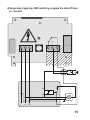
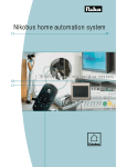
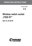
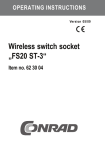
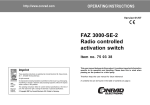
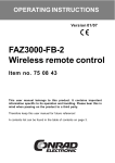
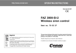
OPERATING INSTRUCTIONS Version 12/06 Wall-mounted remote switch ‘FS20 AS1’ Item no. 62 03 37 Table of contents Page 1. 2. 3. 4. 5. 6. 7. 8. 9. 10. 11. 12. 13. 14. 15. 16. 17. 18. 2 Introduction ....................................................................................... 3 Prescribed use ................................................................................. 4 Scope of delivery ............................................................................. 4 Explanation of icons ......................................................................... 5 Safety instructions ........................................................................... 5 Description of functions ................................................................... 7 Preparation for operation and assembly ........................................ 8 Operating modes ........................................................................... 16 Programming/operation ................................................................. 17 a) Programming ........................................................................... 17 b) Operation ................................................................................. 17 Timer function ................................................................................ 19 a) Programming the timer ............................................................ 19 b) Timer operation ........................................................................ 20 1. Starting the timer ............................................................... 20 2. Turning off the timer ahead of time .................................. 20 3. Deleting the timer function ................................................ 20 4. Activating/deactivating programmed timers .................... 20 Integrating the ‘FS20 AS1’ into the FS20 address system ......... 22 a) Assigning further addresses/address types .......................... 22 b) Deleting addresses/address types ......................................... 22 Resetting the settings .................................................................... 23 Range/reception disturbances ...................................................... 24 Maintenance ................................................................................... 25 Handling ......................................................................................... 25 Disposal .......................................................................................... 26 Technical specifications and features .......................................... 27 Declaration of conformity (DOC) .................................................. 27 1. Introduction Dear customer, Thank you for purchasing this product. This product meets the requirements of both current national and European guidelines. In order to ensure continued fulfilment of legal requirements and safe operation of this product, we kindly ask you to carefully follow the instructions in this user manual! Please read the user manual completely and observe the safety and operation instructions before using the product! All company and product names contained herein are trademarks of their respective owners. All rights reserved. For more inquiries, contact or consult our technical service: Germany: Tel. no.: +49 9604 / 40 88 80 Fax. no.: +49 9604 / 40 88 48 e-mail: [email protected] Mon. to Thur. 8.00am to 4.30pm Fri. 8.00am to 2.00pm 3 2. Prescribed use The wall-mounted remote switch ‘FS20 AS1’ is for remote switching of stationary consumers with a power consumption of up to 3680VA connected to a AC voltage with 230V~/50Hz in conditions described by the technical specifications and safety instructions. The installation instructions must be followed exactly when using the potential-free switching contact separate from the power supply. The device can be operated directly or with a wireless remote control of the FS20 system. In order to ensure proper functioning, the assembly instructions in this manual must be followed. The device may not be altered or converted. The manufacturer does not take any responsibility for incorrect use. All guarantees will be invalidated in any such cases. Any other use may damage the product, and there are also other dangers. Read these operating instructions thoroughly and carefully, as they contain a great deal of important information for the operation and handling. Please take special note of the safety instructions for dealing with voltage-carrying parts! 3. Scope of delivery • Wall-mounted remote switch ‘FS20 AS1’ • User manual 4 4. Explanation of icons The icon with a lightning flash in a triangle is used to alert you to potential personal injury hazards such as electric shock. The icon with an exclamation mark in a triangle points to important instructions in this user manual that must be observed. The ‘hand’ symbol indicates special tips and information on operation. 5. Safety instructions The product’s guarantee becomes invalid if the product is damaged as a result of failure to observe these operating instructions. We do not assume any liability for any resulting damages! Nor do we assume liability for damage to property or personal injury caused by improper use or failure to observe the safety instructions. In such cases the product’s guarantee becomes invalid! • For safety and licensing (CE) reasons any unauthorised conversion, disassembly and/or modification of the product is not permitted. • The product is not a toy and should be kept out of the reach of children. • In order for the device to be connected to the supply voltage and the consumer load work needs to be carried out on live voltage-carrying parts. Completely disconnect the device from the power supply before removing the control panel cover and ensure that the supply voltage cannot be turned on again by a third-party during the course of the work. 5 • Make sure to always put back the control panel cover and screw it down tightly before turning the supply voltage back on. • Only people who are appropriately trained are permitted to carry out work on voltage-carrying parts. If you are not appropriately trained, please consult a qualified electrician who is authorised to carry out such work. • Make sure you only load the product up to the capacity indicated. An overload may lead to the destruction of the device, a fire or an electrical accident. • Do not use inadequate power cords. These should be sized according to the load to be connected. • Aside from installation inside, the device can be installed outside, in damp rooms and areas with high levels of dust as long as the assembly and operating instructions are followed. The product then has the protection class IP 65 (protection against contact and protection against penetration of dust and hose water). • Only rigid installation cables that are designed for fixed installations may be connected to the device. The device must be securely attached within a fixed installation. • Do not leave packaging material lying around. This may become a dangerous plaything in the hands of children. • The accident-prevention regulations, established by the Employer’s Liability Insurance Association for electrical equipment and facilities, must be adhered to in commercial facilities. 6 6. Description of functions The programmable wall-mounted remote switch ‘FS20 AS1’ is a part of the 868 MHz wireless remote switching system FS20 and enables remote controlled switching of loads up to 3680VA (230V~/16A, potential-free switching contact) over a distance of up to 100 m (free-field range). It is designed especially for remote switching of stationary objects such as garage doors, door openers, pumps, lamps, etc. The potential-free switching contacts allow the device to also control switching inputs, 12 V lighting systems, etc. The ‘FS20 AS1’ can easily be integrated into a stationary wiring system. The remote switch can be operated directly as well as from a distance of up to 100 m using the FS20 system’s remote control and other remote switch transmitters. In addition to normal switching (on/off), a switch-off timer is available that can be activated and set between 1 second and 4.5 hours. This timer automatically switches off a turned-on consumer load after the programmed time has run down. Due to its weatherproof casing with a protection class IP 65, the device can also be used outdoors as long as all necessary measures are taken during assembly. Due to the 65,536 selectable house codes and 256 possible addresses, a high level of security against accidental switching is ensured. 7 7. Preparation for operation and assembly The installation location is partially dependent on potentially pre-existing stationary power supply wiring and, more importantly, on an adequate reception of the wireless signal. For more information please read the section ‘Range/reception disturbances’. For this reason you should test that the receiver can receive the switching commands of the remote control at all times before final assembly. There should be no large metal surfaces near the installation location and no cables should run directly by the receiver module. Caution! Before connecting the remote switch to the consumer load to be switched and to the 230V power supply, the fuses of the corresponding electrical circuits must be removed (or the circuit breaker turned off) and it should be tested that there is in fact no voltage in the line with an appropriate voltage tester. The distributor must be secured against unauthorised turning on and a warning sign must be hung up. Proceed as follows: 1. Open the remote switch by removing the casing cover (4 screws). 2. Mount the device above the four mounting holes in the casing corners at the installation location so that the cable openings in the casing lead downwards and the fixed installation wiring can be securely lead into the device. 3. Screw the control panel cover off and carefully remove it from the casing. 4. On the circuit board there are two screw-terminal blocks. The power cable and the lines to the load will be connected here. 5. Prepare the cable ends by stripping them. 8 6. After loosening the fastening nuts slightly, lead the cable ends into the casing through the cable bushings on the underside of the casing. 7. First, wire the cables for the load on KL1 and then to the power supply on KL2 according to the desired task. The potential-free relay contact can be used as a normally closed contact as well as a normally open contact. A wiring diagram as well as a number of suggested uses can be found on the next pages. Caution! Please note that the power cables to the remote switch are only for supply power to the remote switch and not for the consumer load! These must be connected using appropriate branches in the stationary electrical wiring. In the case that voltages independent of the supply voltage, for instance, 12 V from a transformer, or switching inputs, for instance, from a garage door motor, are to be switched, then their wiring must have a safety clearance of at least 8 mm from the supply voltage that is freely lead to the circuit board. The area in which this wiring may be lead has a hatched marking on the application circuits. For this reason you must lead the wiring to KL1 straight down from the circuit board and out of the casing. Never deposit extra wiring length in the casing! 9 Warning! The circuit is operated with a capacitor power supply, meaning there is no galvanic separation of the supply voltage! This dangerous voltage is everywhere on the circuit board and components except in the area of the relay contacts (see hatching in the application circuits). An electric shock can be fatal! 8. Screw the nuts of the cable bushings tight and then place the control panel cover back in. Be sure that the push button cap comes through the corresponding hole. 9. Seal unused cable bushings. 10. You can now connect the power cables to the power grid. 11. After programming, put the casing cover on and screw it down. Be careful to make sure that the cover’s rubber seal sits in its groove properly and does not get pinched when you screw on the cover. When operated in clean and dry conditions, the cover does not have to be used, allowing the device to be operated with the internal buttons and without the remote control. 10 Wiring diagram, location of control panel and indicators 1 L KL 2 N PE LED KL 1 NC NO COM REL 1 Taste L N 2 PE 3 1 Radio receiver 2 Connection to the supply voltage (230V~/50Hz) 3 Load connection 11 Suggested uses The low-voltage cable may only be laid down in the hatched area! Otherwise, there is risk of a fatal electric shock! a) Switching of a 230V consumer REL 1 L 12 N PE b) Switching of a 12V consumer REL 1 L N PE 12 V~ 13 c) Surge relay triggering, 12V switching, program the shut-off timer to 1 second REL 1 A1 1 A2 2 12 V~ L 14 N PE d) Surge relay triggering, 230V switching, program the shut-off timer to 1 second REL 1 L N A1 1 A2 2 PE 15 8. Operating modes The device can be operated directly as well as using a remote switch of the FS20 system. The following description assumes operation with an FS20 handheld transmitter (one button each for ON and OFF). The following operating modes are available: On/off Manual switching of the relay contacts. The outputs remain in the chosen switch state until another switching command is given. Timer Automatic turn off after a defined (1 second to 4.5 hours) time span. Once this time has elapsed, the relay returns to the OFF state. Install the device as described in section 7, do not mount the casing cover yet, and turn on the supply voltage. Briefly press the button of the ‘FS20 AS1’. The load should now turn on and off using the button (first press ‘On’, second press ‘Off’, third press ‘On’, and so on). The LED confirms the respective states (when using the NO contact). 16 9. Programming/operation a) Programming • Press the control button of the ‘FS20 AS1’ for at least 5 seconds. The LED on the ‘FS20 AS1’ begins to blink, and the device is now in programming mode. • Now press one of the buttons of the desired button combination on your remote control. If the ‘FS20 AS1’ has received the code, the control indicator will stop blinking and the remote switch has been programmed for this remote control. • If required, the programming can be replaced at any time by another button on the remote control, as well as by another remote control channel. To do this, proceed again as described above. b) Operation When consumer loads are switched ‘on’, the LED lights up on the remote switch. 1. Remote control operation: Switching on: Briefly press the right button of the programmed button combination Switching off: Briefly press the left button of the programmed button combination 2. Direct operation: Briefly press the button on the remote switch 17 You are now able to use the basic functions of the remote switch. If you would like to expand your wireless control system or to utilise further special functions of the remote switch, please read the following section. You will find detailed instructions for operation and addressing of the respective remote control in its manual. 18 10. Timer function The remote switch can also be used as a timer. That means that when a switch time has been programmed, after every power-on command the switch will stay on for the programmed time and then turn off when this time has elapsed. The timer can be programmed with a on-time between 1 second and 4.5 hours. In order to program the timers you require a remote control from the FS20 wireless control system. a) Programming the timer • Simultaneously press and hold both of the buttons of the respective button combination on the remote control for your remote switch for 1 to 5 seconds. • The control indicator on the remote switch blinks; the time measurement for the timer is started. • Wait the required amount of time and then press both buttons on the remote control again simultaneously for one to five seconds (1 sec to 5 sec). The timer duration is now programmed. Please note: If the time measurement is not ended manually, the timer programming mode will automatically be abandoned after 4.5 hours. The timer is then programmed with a time of 4.5 hours. 19 b) Timer operation 1. Starting the timer Briefly press the control button on the remote switch. Or: Briefly press the right button of the corresponding button combination of your remote control. 2. Turning off the timer ahead of time The remote switch can be turned off manually at any time: Briefly press the control button on the remote switch. Or: Briefly press the left button of the corresponding button combination on your remote control. 3. Deleting the timer function Simultaneously press and hold the respective button combination on the remote control for your remote switch for 1 to 5 seconds. The LED of the remote switch blinks. Briefly press the control button on the remote switch. The switch has left the timer program mode and the timer function is removed (the programmed timer setting is deleted). You can now use the remote switch in its normal manual operation. 4. Activating/deactivating programmed timers If you don’t want to use the timer but would like to keep the programmed timer settings, then you can simply deactivate the timer. You can then use the remote switch in its normal manual operation. If desired, you can use the timer again without having to program the settings. 20 Deactivating the timer: Simultaneously press and hold both of the buttons of the respective button combination on the remote control for your remote switch for 1 to 5 seconds. The control indicator of the remote switch blinks. Press and hold the left button of the corresponding button combination on your remote control for at least 0.4 seconds. The remote switch can now be switched manually: The timer is deactivated. Reactivating the timer: Simultaneously press and hold both of the buttons of the respective button combination on the remote control for your remote switch for 1 to 5 seconds. The control indicator of the remote switch blinks. Press the right button of the assigned button combination on your remote control for longer than 0.4 seconds. Now the timer is active again and can be started the next time the switch is turned to the on state. 21 11. Integrating the ‘FS20 AS1’ in the FS20 address system The ‘FS20 AS1’ can be integrated into the address system of the FS20 wireless control system via the latter’s addressing scheme using single addresses, function groups, local and global masters. More detailed information on exactly how this address system is structured is provided in the user manual of each transmitter belonging to the FS20 wireless control system. a) Assigning further addresses/address types Up to four address types can be assigned to the ‘FS20 AS1’ within the address system of the FS20 system. This makes it possible, for example, to operate the switch remotely from several transmitters with the same or different address types. You can find more detailed information on the address system in the user manual of each remote control belonging to the system. To assign several address types to the ‘FS20 AS1’, repeat the programming steps described in section 9. You can create a list of up to four addresses or address types in the memory of the ‘FS20 AS1’. b) Deleting addresses/address types When you would like to delete a reception channel from the saved list, place the remote switch in programming mode according to the instructions in section 9. Now you press and hold (for at least 0.4 seconds) the button on your remote control that has been designated to the reception channel that you wish to delete. Afterwards, the programming mode is automatically abandoned and the corresponding channel is deleted from the remote switch’s address list. 22 12. Resetting the settings If required, you can delete all the settings that are stored in the remote switch at once. • Press the control button of the ‘FS20 AS1’ for at least 5 seconds. The LED on the ‘FS20 AS1’ begins to blink, and the device is now in programming mode. • Briefly press the control button again. All assigned addresses and the timer mode with its programmed timer setting are deleted or deactivated. • The LED going out, signals that the programming mode has been exited. The remote switch no longer responds to any remote command and must be programmed again! 23 13. Range/reception disturbances The free-field range, that is, the range within visual contact between the transmitter and receiver is 100 m under optimal conditions. The signal can go through walls and even reinforced concrete, but the range will be reduced. Test the reception at different times of day before installation. If necessary, you can use an FS20 system repeater to increase the range. Please note: Do not position several radio switches directly next to each other, as these can interfere with each other (minimum distance 0.2 m, we recommend 0.5 m or more). A reduced range can have the following causes: • All types of high-frequency interference • All buildings or vegetation. Especially within metal structures, the range can be reduced greatly due to attenuation and distortion. • The distance of the transmitter or receiver to conductive surfaces or objects (also to human bodies or the ground) influences the radiation pattern and with it the range. • Broadband interference in urban areas can reach levels that diminish the signal-to-noise ratio, thus reducing the range. • Devices with neighbouring working frequencies can also influence the receiver. • Poorly shielded or openly operating computers can radiate into the receiver and reduce the range. 24 14. Maintenance This product does not require maintenance. Please let a professional workshop carry out the necessary repairs. 15. Handling Take note of all the safety instructions in this user manual. Due to its construction, the product can be used outdoors provided that the casing is fully and correctly closed. At the same time the product must be assembled and wired properly and professionally. Only people who are appropriately trained are permitted to carry out work on voltage-carrying parts. If you are not appropriately trained, please consult a qualified electrician who is authorised to carry out such work. Never use the product immediately after it has been brought from a cold room into a warm one. The condensation that forms could damage the device! Leave the product switched off and wait until it has reached room temperature before turning it on or installing it. This may take several hours. Make sure that the insulation of the entire product is neither damaged nor destroyed. Normally the product is installed once and then remains fixed at the installation location. Depending on the installation location, check occasionally if the product is in perfect condition. 25 16. Disposal 26 When the product is no longer usable dispose of it in accordance with the applicable statutory regulations. 17. Technical specifications and features Operating voltage: .............................. 230V~/50Hz Reception frequency: ......................... 868.35 MHz Range: ................................................. up to 100 m (free-field) Power consumption: ........................... 0.5W Breaking capacity: .............................. 3680VA (230V~, 16A) Switching output: ................................ potential-free switch-over contact Programmable timer settings: ........... 1 second to 4.5 hours Dimensions (W x H x D): ................... 115 x 90 x 55 mm Casing protection class: .................... IP 65 18. Declaration of conformity (DOC) We, Conrad Electronic, Klaus-Conrad-Straße 1, D-92240 Hirschau (Germany), hereby declare that this product complies with the fundamental requirements and other relevant regulations of directive 1999/5/EG. You can find the declaration of conformity for this product at www.conrad.com 27 http://www.conrad.com Imprint These operating instructions are published by Conrad Electronic SE, Klaus-Conrad-Str. 1, D-92240 Hirschau/Germany. No reproduction (including translation) is permitted in whole or part e.g. photocopy, microfilming or storage in electronic data processing equipment, without the express written consent of the publisher. 100% recycling paper. The operating instructions reflect the current technical specifications at time of print. Bleached without chlorine. © Copyright 2006 by Conrad Electronic SE. Printed in Germany. We reserve the right to change the technical or physical specifications.