1
GSR-12 / 16 / 18 / 24
AS-12 / 16
GCR-12 / 16
User Manual Appendix G
Interconnected Recording Networks
GeoSIG Ltd, Ahornweg 5A, 5504 Othmarsingen, Switzerland
Phone: + 41 44 810 2150, Fax: + 41 44 810 2350
[email protected], www.geosig.com
GS_GSR_GCR_UserManual_App_G_Interconnection_V01.doc / 08.12.2010
Appendix G
ii
Document Revision
Author
Checked
Approved
Patrick Camina
Ricardo Araujo
Christoph Kündig
Version
04.10.2006
Action
First issue: Re-structured document replacing TN_93_SMI_InterconnNet.doc and
pointing out practical aspects such as installation.
Adjustment regarding standard telephone cable in Chapter “Interconnection Cable”,
PC
First level approval with some formatting and relocation, TB
AC connection pin description (Central Communication Box) added, PC
Housing sizes inserted under pictures, TB
09.10.2006
07.11.2006
15.11.2006
08.10.2007
Disclaimer
GeoSIG Ltd reserves the right to change the information contained in this document without notice. While the information contained
herein is assumed to be accurate, GeoSIG Ltd assumes no responsibility for any errors or omissions.
Copyright Notice
No part of this document may be reproduced without the prior written consent of GeoSIG Ltd. The software described in this document
is furnished under a license and may only be used or copied in accordance with the terms of such a license.
Trademark
All brand and product names mentioned are trademarks or registered trademarks of their respective holders.
All rights reserved.
GeoSIG Ltd
Switzerland
GS_GSR_GCR_UserManual_App_G_Interconnection_V01.doc / 08.12.2010
Appendix G
3
Table of Contents
Introduction.......................................................................................................................... 4
1. Description and Functionality........................................................................................... 4
1.1. Common Functionality ............................................................................................................................4
1.1.1. Type A: CCL
(Common Time, Common Trigger, Local Communication)...................................5
1.1.2. Type B: CCC
(Common Time, Common Trigger, Central Communication) ...............................5
1.1.3. Type C: CCM
(Common Time, Common Trigger, Multinode Communication) ..........................5
1.1.4. Comparison of Options ....................................................................................................................5
2. Installation ....................................................................................................................... 7
2.1. Physical Interconnection .........................................................................................................................7
2.1.1. Central Communication Box ............................................................................................................9
2.1.2. Interconnection Signals .................................................................................................................12
2.1.3. Interconnection Cable....................................................................................................................13
2.2. Interconnected Recorders.....................................................................................................................13
2.2.1. CCL................................................................................................................................................13
2.2.2. CCC ...............................................................................................................................................14
2.2.3. CCM...............................................................................................................................................14
2.2.4. Software Configuration ..................................................................................................................18
2.3. Verification of the Installation ................................................................................................................19
GS_GSR_GCR_UserManual_App_G_Interconnection_V01.doc / 08.12.2010
Appendix G
4
Introduction
When interconnection is involved, more options are available in terms of connections, data flow,
accessibility, and cost. One version is the Interconnected Recording Network which uses local recording.
The three possible types of the Interconnected Recording Network are explained in detail in “TN # 85: Strong
Motion Instrumentation Networks”. This document describes practical aspects concerning installation and
their use.
1. Description and Functionality
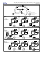
The three types of the Interconnected Recording Network (Interconnection Network) are illustrated in Figure
1 and are described below. A brief functional comparison is also presented in Table 1.
1.1. Common Functionality
Connections: Several recorders with internal or external sensors are placed on site and are interconnected
with one cable while galvanically isolated from each other. For convenient cabling external junction boxes
are used. The interconnection between the stations can be carried out in ring, star, or net topology.
Distances between the stations can be as much as 1 km. This is a favourable and cost effective solution for
many applications.
Common Timing: One of the interconnected recorders (commonly referred to as the Software Master) is
enabled to synchronise and update the internal clock of each of the other recorders (commonly referred to as
Software Slaves) via the network to achieve Common Timing. All stations within the network use this
common time information to synchronise their internal time. The time synchronisation is a permanent task for
the Software Master. The stations within the network permanently check their synchronisation status. In case
of not having the network time information available, the Slave stations base on their internal real time clock.
The time of the last successful synchronisation is available in the status information of a Slave station and is
written into every event header. A GPS time source can be connected to the Software Master to achieve the
time synchronisation of the whole array to the absolute time, which allows easier correlation with recordings
made by other arrays or recorders.
Common Trigger: Triggering functionality of each recorder can be controlled using three flags: 'Internal
Trigger', 'Network Trigger Output' and 'Network Trigger Input'. By enabling or disabling these flags the
behaviour of each station can be defined precisely as needed in the particular application. This functionality
can be summarised as follows:
• Enable / disable self trigger:
The station triggers if an internal trigger condition is fulfilled and the 'Internal Trigger' flag is
enabled.
• Enable / disable sending trigger to network:
The station transmits an active trigger message to the network if an internal trigger condition is
fulfilled and the 'Network Trigger Output' flag is enabled.
• Enable / disable accepting trigger from network:
The station triggers if an active trigger message arrives from the network and the 'Network Trigger
Input’ flag is enabled.
If a station is not synchronised to the network it records based on the specified internal trigger condition. An
output for Local Communication is available at each recorder for local data retrieval and setting of
parameters. The reliability of the monitoring network is high, because a malfunction of a recorder would
affect only the location of malfunction in the array. If the network is interrupted, each of the recorders will
perform as a stand-alone recorder by recording whenever the instrument’s event-recording trigger level is
reached.
GS_GSR_GCR_UserManual_App_G_Interconnection_V01.doc / 08.12.2010
Appendix G
1.1.1. Type A: CCL
5
(Common Time, Common Trigger, Local Communication)
This type of array enables common triggering and common time in the simplest form. The data are stored
locally in every recorder and have to be retrieved locally from each recorder separately, due to the
availability of Local Communication only. Similarly, the setting of parameters of each recorder has to be
performed on the site of each recorder.
a
A shielded cable with a single twisted pair is sufficient for this type.
1.1.2. Type B: CCC
(Common Time, Common Trigger, Central Communication)
A central communication module is utilised in this option. The module is connected to the network as a
central, from which all of the recorders can be accessed for data retrieval and setting of the parameters.
a
Due to the communication option a shielded cable consisting of 3 twisted pairs is required.
1.1.3. Type C: CCM
(Common Time, Common Trigger, Multinode Communication)
The data of every recorder can be accessed and retrieved from any of the recorders in the array. Similarly
the parameters of every recorder is adjustable from any of the accessed recorders. This provides an
extremely versatile system to operate.
a
As for the previous type a shielded cable consisting of 3 twisted pairs is required.
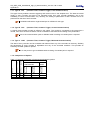
1.1.4. Comparison of Options
To Local
Recorder
To Every
Recorder
To Every
Recorder
CCL 9
CCC 9
CCM 9
Common Triggering
Common Timing
Option
Table 1. Functional comparison of interconnected network options
Communication from
Central
Local Recorder
Module
9
9
9
9
9
9
9
9
(9)
GS_GSR_GCR_UserManual_App_G_Interconnection_V01.doc / 08.12.2010
Appendix G
6
ST2
ST1
ST4
ST3
CM
ST: Station
ST5
CM: Central Module (Option B only)
ST6
: Communication to all recorders
: Local Communication
Option A
GPS
Station n = 1
Station n = 2
Station n = N
CCL
Common Time
Common Trigger
Local Communication
Recorder
Recorder
Recorder
Sensor
Sensor
Modem
Modem
Junction
Box
Sensor
Modem
Junction
Box
Junction
Box
Option B
GPS
Station n = 1
CCC
Station n = 2
Station n = N
Common Time
Common Trigger
Central Communication
Recorder
Recorder
Recorder
Sensor
Sensor
Sensor
Modem
Junction
Box
Central
Module
Junction
Box
Junction
Box
Option C
GPS
Station n = 1
CCM
Station n = 2
Station n = N
Common Time
Common Trigger
Multinode Communication
Recorder
Recorder
Sensor
Modem
Modem
Junction
Box
Recorder
Sensor
Sensor
Modem
Junction
Box
Junction
Box
Figure 1. Topology of the Interconnected Recording Network Options
GS_GSR_GCR_UserManual_App_G_Interconnection_V01.doc / 08.12.2010
Appendix G
7
2. Installation
2.1. Physical Interconnection
The principle of the interconnection wiring of all types of networks described above is the same.
Interconnection Junction Boxes are supplied in order to facilitate on-site wiring. Since these networks can
extend over hundreds of meters involving long cables it is important to protect the recorders against overvoltages, such as electrostatic discharges and lightning, and differences in local earth potentials. The
protection is realised in the following ways:
• Advanced Lightning and over-voltage protection is implemented in the Interconnection Junction
Boxes
• An interconnection option board which takes care of the galvanic isolation is installed in the
recorders
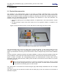
Figure 2 shows the Interconnection Junction Box which is used along with each recorder.
Figure 2. Interconnection Junction Box (150 x 150 x 80 mm)
The interconnection wiring is the only wiring, which is really site-specific, in other words carried out by the
customer. The other wiring, such as INTERCON connection cable, RS-232 PC-connection cable, or AC
cable is pre-assembled. The wiring of the interconnection cable is straight through which makes installation
easy.
In order to achieve a maximum protection and system reliability, a couple of points are important to take care
during installation, mainly earth and cable shield connections. These points are described in the following.
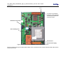
Figure 3 shows a recorder, the corresponding junction box (Interconnection Junction Box) and the
connection of the bus (interconnection) cabling. Each recorder is connected to the bus cable via a junction
box which goes with it.
a
Both, the recorder and the junction box, need to be connected to local earth. There is an earth
screw on both housings which can be used for this purpose. The earth cable is connected first
to the junction box and then goes on to the recorder.
The Junction Box is connected to the recorder using the grey cable already assembled to the box. Its length
is about 1 m.
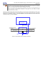
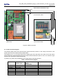
The cable coming from the previous recorder and the cable going to the next recorder are connected as
indicated in Figure 4.
GS_GSR_GCR_UserManual_App_G_Interconnection_V01.doc / 08.12.2010
Appendix G
8
a
The shields of the interconnection cables are connected to the yellow connectors as indicated
in Figure 4. Do not connect them to the housing or local earth!
There is one exception where the shield is connected to local earth. It is in the junction box of
the first recorder in Interconnection Networks of the type CCL and CCM (no Central
Communication Box is used)!
This way, the cable shield of the interconnection cable is only at one point connected directly to earth. At the
other junctions it is connected via an over-voltage breaker. This makes sure that there are no electrical
problems (no equalisation currents) in case the potentials of the local earths are not the same. This
commonly occurs e.g. in dam installations.
GSR/GCR recorder
OPTION
“Interconnection”
Intercon plug
To previous recorder
or PC (BUS)
Junction
Box
Cable shield
To next recorder (BUS)
Cable shield
Local ProtectionEarth
Figure 3. Interconnection wiring, including Junction Box
GS_GSR_GCR_UserManual_App_G_Interconnection_V01.doc / 08.12.2010
Appendix G
9
To Intercon
plug of GXR
To previous
recorder or PC
(BUS)
Pin 1
Shields of in-coming
and out-going BUS
DO NOT CONNECT
BUS-SHIELDS TO
HOUSING!
To next
recorder
(BUS)
Pin 1
Figure 4. Connectors inside Junction Box
2.1.1. Central Communication Box
The Interconnection Network type CCC uses a Central Communication Box at which in general a Computer
is connected (see Figure 5).
Figure 5. Central Communication Box (300 x 200 x 120/140 mm)
The Computer is connected using the standard RS-232 cable delivered with the shipment. The AC power
cable is generally already assembled to the box. Figure 6 shows the connection diagram of the Central
Communication Box.
GS_GSR_GCR_UserManual_App_G_Interconnection_V01.doc / 08.12.2010
Appendix G
10
Central Communication
Box:
PC
•
•
Overvoltage
protection
RS-232/RS-485
conversion
Local ProtectionEarth
15 VDC or
230 VAC
Figure 6. Interconnection Wiring, incl. Central Communication Box
The following table shows the connection of the AC power cable. Its location on the card is indicated in
Figure 7. Connectors and fuses inside Central Communication Box.
Table 2. AC Connector Description
Signal
PE, Protection Earth
--L, Phase
---N, Neutral
Colour
Yellow-green
--Brown
---Light-Blue
Pin
1
2
3
4
5
6
7
8
a
Make sure that the AC main supply is disconnected before starting to manipulate
connections inside the box
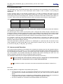
The interconnection cable is connected as indicated in Figure 7. It is the top connector, not to be confused
with the main supply connector on the bottom.
a
The interconnection cable shield needs to be connected to the EMV-stuffing tube. It is here
where the entire cable shield is connected to earth.
The box itself is connected to earth with the earth signal (yellow-green) in the main supply cable or in newer
instruments by the earth screw on the outside of the box.
GS_GSR_GCR_UserManual_App_G_Interconnection_V01.doc / 08.12.2010
Appendix G
11
Pin 1
To closest recorder (BUS)
CONNECT CABLE-SHIELD
TO HOUSING USING EMVSTUFFING-TUBE!
RS-232 PC-connection
DC secondary fuse
Pin 1
230 VAC fuse
230 VAC main supply
Figure 7. Connectors and fuses inside Central Communication Box
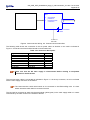
Figure 8 shows the way the cable shield needs to be connected to the Central Communication Box and to
the junction boxes.
GS_GSR_GCR_UserManual_App_G_Interconnection_V01.doc / 08.12.2010
Appendix G
12
Cable shield connected here only!
Interconnection cable
Central Communication Box
(Next to PC)
Interconnection Junction Box
(next to first recorder)
Figure 8. Shield connection
2.1.2. Interconnection Signals
The following table shows the Interconnection signals and their position on the orange connectors in the
junction box and in the Central Communication Box.
The signals on pin 1 to 4 are only used for the network types CCC and CCM. In the case of CCC the names
given indicate the signal directions from the Central Communication Box point of view. In a network of type
CCM the four signals are used bi-directionally.
N_PWR is only used if the Centralised Power Supply Option has been selected.
Table 3. Interconnection Signals
Signal
Needed for
Network Type
485_TX_H
485_TX_L
485_RX_H
485_RX_L
N_PWR
N_SYNC
N_GND
N_GND
CCC, CCM
CCC, CCM
CCC, CCM
CCC, CCM
Optional
CCC, CCM, CCL
CCC, CCM, CCL
Central Communication
Box or
Junction Box
1
2
3
4
5
6
7
8
Next Junction Box
1
2
3
4
5
6
7
8
GS_GSR_GCR_UserManual_App_G_Interconnection_V01.doc / 08.12.2010
Appendix G
13
2.1.3. Interconnection Cable
The appropriate choice of the interconnection cable is important for the functionality of the network. For all
network types the cable has to have twisted-pairs and a shield in order to prevent it from picking up
interference.
Another important aspect is the diameter required which is a trade off between total length of the bus
network and cable diameter. Since the signal which takes care of Common Time and Common Trigger is a
current signal (30 mA) it is the limiting factor. Therefore, the maximum total cable resistance (both ways) is 2
* 50 Ohm. Table 3 shows the relationship between cable cross-sections and maximum network lengths.
Table 4. Cable cross-sections vs. maximum network length
Cross-section
Resistance
Maximum network length
[Ohm/km]
[m]
[mm2]
0.20
89.0
500
0.25
71.2
700
0.35
50.9
900
0.5
36.6
1300
A way to reduce the cable resistance is to connect two pairs in parallel. This effectively halves the resistance
and doubles the maximum length.
For network types which involve communication (CCC, CCM) the total network length is advised to be a
maximum of 1000 m. However, lengths above 1000 m are possible but the maximum communication speed
for reliable connections is decreasing with increasing distance. Please contact GeoSIG Ltd. in such a case.
Another option for long-distance interconnection networks is a transmission based on fibre optics.
For a network of type CCL only one twisted-pair is required which is connected to N_SYNC (pin 6) and
N_GND (pin 7) of the orange connectors. In the case of short in-door networks (up to 200 m) a standard
telephone cable (without shield) is sufficient.
CCC and CCM require a cable with a minimum of 3 twisted-pairs. If 4 pairs are used, two of them can be
used in parallel for N_SYNC and N_GND. In any case one pair is used for 485_TX_H / 485_TX_L (pin 1 and
2), and one for 485_RX_H / 485_RX_L (pin 3 and 4).
2.2. Interconnected Recorders
In an Interconnection Network not all recorders are configured in the same way from the hardware and from
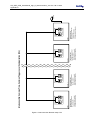
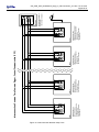
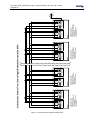
the software point of view. Figures 9, 10, and 11 show the setup and position of the individual recorders in
the corresponding bus network. The text in the Figures below each recorder describes its configuration and
role in the network. The recorders themselves are identified with labels containing the same text. The
following Chapters describe this issue for the different types of networks.
The individual recorders are pre-configured (hardware and software) in the factory.
a
Do not change the interconnection network specific configuration as described below
unless there is a strong reason to do so (check with GeoSIG Ltd.)!
a
The maximum number of recorders in an Interconnected Recorder Network is limited to 10.
2.2.1. CCL
The following different configurations are possible (see Figure 9):
• The first recorder in the bus is configured as Network Driver and has therefore jumpers J91 and
J92 inserted on the internal interconnection card GS_ICC_V05. There can only be one Network
Driver!
• The first recorder in the bus is configured as Software Master, whereas all the other recorders are
configured as Software Slaves. Refer to Chapter “Software Configuration” below
• If a GPS is available it is connected to the Software Master (first instrument)
GS_GSR_GCR_UserManual_App_G_Interconnection_V01.doc / 08.12.2010
Appendix G
14
To summarise, there are two types of instrument configurations:
• GXR Interconnection Master (first)
• GXR Interconnection Slave (all, except first)
a
OVP boxes are not shown in Figure 9.
2.2.2. CCC
The following different configurations are possible (see Figure 10):
• The Central Communication Box serves as Network Driver. Since there is only one network driver
required the jumpers J91 and J92 on the internal interconnection card GS_ICC_V05 of the
recorders are not inserted.
• The first recorder in the bus is configured as Software Master, whereas all the other recorders are
configured as Software Slaves. Refer to Chapter “Software Configuration” below
• If a GPS is available it is connected to the Software Master (first instrument)
• Communication through the network requires terminations in the first node of the network (Central
Communication Box) and in the last one (last recorder)
To summarise, there are three types of instrument configurations:
• GXR Master without Termination (first recorder closest to Central Communication Box)
• GXR Slave without Termination (all, except first and last)
• GXR Slave with Termination (last instrument)
a
OVP boxes and Common Time / Common Trigger wiring is not shown in Figure 10.
2.2.3. CCM
The following configurations are possible (see Figure 11):
• The first recorder in the bus is configured as Network Driver and has therefore jumpers J91 and
J92 inserted on the internal interconnection card GS_ICC_V05. There can only be one Network
Driver!
• The first recorder in the bus is configured as Software Master, whereas all the other recorders are
configured as Software Slaves. Refer to Chapter “Software Configuration” below.
• If a GPS is available it is connected to the Software Master (first instrument)
• Communication through the network requires terminations in the first and in the last recorder
To summarise, there are three types of instrument configurations:
• GXR Master with Termination (first)
• GXR Slave without Termination (all, except first and last)
• GXR Slave with Termination (last instrument)
a
OVP boxes and Common Time / Common Trigger wiring is not shown in Figure 11.
Figure 9. Interconnection Network setup CCL
Interconnection CCL
GXR Interconnection Slave
- No network driver
(J91 and J92 not inserted)
- Software slave configuration
GXR n
GS_ICC.V05.A1
Interconnection CCL
GXR Interconnection Slave
- No network driver
(J91 and J92 not inserted)
- Software slave configuration
GXR n - 1
GS_ICC.V05.A1
Interconnection CCL
GXR Interconnection Slave
- No network driver
(J91 and J92 not inserted)
- Software slave configuration
GXR 2
GS_ICC.V05.A1
Interconnection: Common Time, Common Trigger, Local Communication (CCL)
Interconnection CCL
GXR Interconnection Master
- Network driver
(J91 and J92 inserted)
- Software master configuration
GXR 1
GS_ICC.V05.A1
GPS
(optional)
GS_GSR_GCR_UserManual_App_G_Interconnection_V01.doc / 08.12.2010
Appendix G
15
Figure 10. Interconnection Network setup CCC
1k
1k
Interconnection CCC
GXR with Termination
- Software slave configuration
- No network driver
(J91 and J92 not inserted)
- Last instrument
GXR n
120
GS_ICC.V05.A3
10k
Interconnection CCC
GXR without Termination
- Software slave configuration
- No network driver
(J91 and J92 not inserted)
GXR n - 1
10k
GS_ICC.V05.A2
10k
Interconnection CCC
GXR without Termination
- Software slave configuration
- No network driver
(J91 and J92 not inserted)
GXR 2
GS_ICC.V05.A2
10k
Interconnection: Common Time, Common Trigger, Central Communication (CCC)
10k
GXR-ICCCB
GS_ICD.V05
1k
GPS
(optional)
Central Communication Box
- Network driver
- Interconnection termination
Interconnection CCC
GXR Master without Termination
- Software master configuration
- No network driver
(J91 and J92 not inserted)
- First instrument
GXR 1
10k
GS_ICC.V05.A2
1k
120
16
GS_GSR_GCR_UserManual_App_G_Interconnection_V01.doc / 08.12.2010
Appendix G
120
1k
1k
Figure 11. Interconnection Network setup CCM
120
1k
1k
GS_ICC.V05.A5
Interconnection CCM
GXR with Termination
- Software slave configuration
- No network driver
(J91 and J92 not inserted)
- Last instrument
GXR n
GS_ICC.V05.A3
10k
10k
10k
10k
GS_ICC.V05.A4
Interconnection CCM
GXR without Termination
- Software slave configuration
- No network driver
(J91 and J92 not inserted)
GXR n - 1
GS_ICC.V05.A2
10k
10k
10k
GS_ICC.V05.A4
Interconnection CCM
GXR without Termination
- Software slave configuration
- No network driver
(J91 and J92 not inserted)
GXR 2
GS_ICC.V05.A2
10k
Interconnection: Common Time, Common Trigger, Multinode Communication (CCM)
120
1k
1k
120
1k
1k
GS_ICC.V05.A5
Interconnection CCM
GXR Master with Termination
- Software master configuration
- Network driver
(J91 and J92 inserted)
- First instrument
GXR 1
GS_ICC.V05.A3
GPS
(optional)
GS_GSR_GCR_UserManual_App_G_Interconnection_V01.doc / 08.12.2010
Appendix G
17
GS_GSR_GCR_UserManual_App_G_Interconnection_V01.doc / 08.12.2010
Appendix G
18
2.2.4. Software Configuration
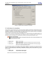
In order to allow Common Time and Common Trigger in the network the recorders need to be configured to
this respect.
Figure 12 shows the configuration of the Software Master. The following ticks are fixed and cannot be
changed.
Software Master:
• Enable Network Synchronisation
• Network Master Mode
Figure 13 shows the configuration of the Software Slave. The following ticks are fixed and cannot be
changed.
Software Slave:
• Enable Network Synchronisation
• Network Master Mode IS NOT TICKED
Optional:
• Input Network Trigger
• Output Network Trigger
• Synchronise Slave Clock to Network Clock
For a description of the Synchronisation options please refer to Chapter 1. For more details on the use of
GeoDAS please refer to the GeoDAS Software Manual.
Figure 12. Software Master configuration in GeoDAS
GS_GSR_GCR_UserManual_App_G_Interconnection_V01.doc / 08.12.2010
Appendix G
19
Figure 13. Software Slave configuration in GeoDAS
2.3. Verification of the Installation
If the network is synchronised (Common Time and Common Trigger are working) the network status of every
recorder in the network, shows the word Synchronised (see above Figures 12 and 13 where the opposite is
indicated) in GeoDAS. The synchronisation of the date and time of all Software Slaves to the Software
Master should be verified and also the network triggering options.
A simple way to check the wiring during the installation is to verify the arrival of the network signals to an
instrument. For this test the recorders need to be configured correctly. The following LED’s can be found on
the interconnection cards (GS_ICC_V5) inside the recorder (by removing the black plastic cover):
a
Caution: High Voltage!
If you remove the black plastic covering the base part of the recorder housing do not
touch any electronics inside.
• LED90, yellow:
• LED91, red:
• LED92, green:
Blinks in all recorders
Blinks in the recorders configured as Network Drivers and in the Central
Communication Box
Blinks in the recorder configured as Software Master and during a trigger
also in the corresponding Software Slave.
The communication option can be tested by simply trying to establish a connection to the instruments from a
Computer running GeoDAS. The standard communication speed for Interconnection Networks is 38’400
Baud. If communication problems arise during installation the following LED’s, found also on GS_ICC_V5,
can be of help:
• LED60, yellow:
• LED61, green:
Communication transmit signal
Communication receive signal
Both LED’s should blink during successful communication.