1
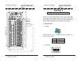
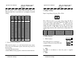
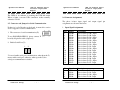
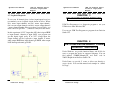
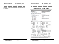
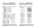
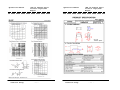
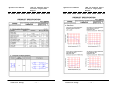
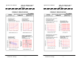
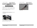
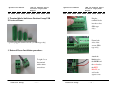
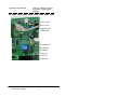
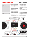
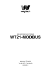
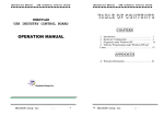
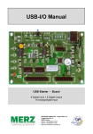
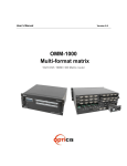
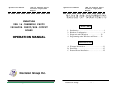
Operations Manual
USB 16 Channel Photo
Isolator Input/SSR
Output
SMARTLAB
USB 16 CHANNELS PHOTO
ISOLATOR INPUT/SSR OUTPUT
BOARD
OPERATION MANUAL
Operations Manual
USB 16 Channel Photo
Isolator Input/SSR
Output
CHAPTERS
1.
2.
3.
4.
Introduction…………………………………..……1
Hardware Configuration…………………..…….....4
Diagnostic under Windows …………………12
Programming under Windows and Linux……12
APPENDICES
A. Warranty Information……………………………13
B. Data Sheet…………..……………………………15
C. External Power Installation………………………25
Decision Group Inc.
Decision Group
- i -
Decision Group
- ii -
Operations Manual
USB 16 Channel Photo
Isolator Input/SSR
Output
CHAPTER 1
INTRODUCTION
The USB 16 channels photo isolator input/output board
provides 16 photo couple digital input/output channels, which
allow the input/output signals to be completely floated and
prevent the ground loop.
The USB 16 channels photo isolator input/output board
provides Plug and Play (PnP) features, it is a programmable I/O
interface board for PC/486, Pentium, or compatibles. The on
board high speed 8051 uC provides USB functions run at
12Mbps full speed or 1.5Mbps low speed.
The features of USB 16 channels photo isolator
input/output board are:
•
•
•
•
•
•
•
•
•
•
•
USB 2.0with Plug and Play (PnP) features.
High speed 8051 uC core.
Support USB ID selection to identify USB device.
Support 16 photo couple input/16 SSR output channels.
Allow the photo input signals to be completely floated
and prevent the ground loops.
32 LED correspond to 16 input and 16 output ports
activation status.
By using PC817 photo couple chips.
KAQY212HA SSR
Power supplied from external DC +5V.
5000V isolation voltage.
Decision Group
- 1 -
Operations Manual
•
•
•
•
•
•
•
•
USB 16 Channel Photo
Isolator Input/SSR
Output
Output break down voltage : +-60V
Continuous load current : +-400mA
Maximum 50mA forward input current.
Input voltage range from 0V to 30V.
Activation voltage of photo input:
When short jumpers (input range from 0 to 20V DC)
0 to 3.3V inactive
4.5 to 20V active
When open jumpers (input range from 0 to 30V DC)
0 to 17.6V inactive
18 to 30V active
Suitable for Linux, MS/Windows ... etc.
Operating temperature range from 0 to 55º C.
Relative humidity rage from 0 to 90%.
PACKAGE CONTENTS:
SMARTLAB USB 16 channels photo isolator input/
SSR output board.
• USB cable.
• Decision Studio and User’s manual CD.
• Two Different Connecter Types can be selected:
Standard: European P.C.B type terminal blocks
Professional: Pluggable terminal blocks
Optional
•
•
•
Extension board with DB9 : RS232 or RS422/485
PCB Carrier
Decision Group
- 2 -
Operations Manual
USB 16 Channel Photo
Isolator Input/SSR
Output
Operations Manual
USB 16 Channel Photo
Isolator Input/SSR
Output
CHAPTER 2
HARDWARE CONFIGURATION
Before you use the USB 16 channels photo couple input/output
board, Please ensure that the jumpers and switches setting. The
proper jumper and switches settings for the 16 channels photo
couple input/output adapter are described in the following.
2.1 Switch Settings
1. S1 Reset
The S1 switch is used to reset 8051, the signal assignments are
shown in the following.
Pin
3,4
1,2
Signals
Reset SW+
Reset SW-
2. S2 USB ID
Decision Group
- 3 -
Decision Group
- 4 -
Operations Manual
USB 16 Channel Photo
Isolator Input/SSR
Output
The S2 switch is used to identify USB board ID. Please set
different board ID to each board (do not duplicate board ID
setting).
1
ON
OFF
ON
OFF
ON
OFF
ON
OFF
ON
OFF
ON
OFF
ON
OFF
ON
OFF
2
ON
ON
OFF
OFF
ON
ON
OFF
OFF
ON
ON
OFF
OFF
ON
ON
OFF
OFF
3
ON
ON
ON
ON
OFF
OFF
OFF
OFF
ON
ON
ON
ON
OFF
OFF
OFF
OFF
4
ON
ON
ON
ON
ON
ON
ON
ON
OFF
OFF
OFF
OFF
OFF
OFF
OFF
OFF
ID
-14
13
12
11
10
9
8
7
6
5
4
3
2
1
0
USB 16 Channel Photo
Isolator Input/SSR
Output
2.2 Jumper Settings
Input Voltage Range Selection (JP1 to JP16)
1 2
. .
JP1 to JP16 are used to select input voltage range. The JP1 is
used to select photo couple input channel 0, and JP2 is used to
select photo couple input channel 1, … etc. When short the
jumper, the input voltage range from 0 to 20V, and the active
voltage form 4.5 to 20V. When open the jumper, the input
voltage range from 0 to 30V, and the active voltage from 18 to
30V.
Jumper Input Voltage Inactive Voltage Active Voltage
open
0 to 30V
0 to 17.6V
18 to 30V
short
0 to 20V
0 to 3.3V
4.5 to 20V
2.3 USB Connector
1. USB Connector
The USB connector is connected to
computer USB port by using USB cable.
3. Down load revised firmware
When the S2 switch is set to ON ON ON ON status, means
down load revised firmware. please follow the steps shown in
the following:
1. Set S2 to ON ON ON ON.
2. Run USBBootloader program to download revised firmware.
Decision Group
Operations Manual
- 5 -
2.4 LED Status
1. LED1
The LED1 is an indicator to show the power is supplied
normally.
2. LED2
Decision Group
- 6 -
Operations Manual
USB 16 Channel Photo
Isolator Input/SSR
Output
The LED2 is an indicator to warning the USB link status.
When it lights, it means USB connection works normally,
otherwise it is fail.
2.5 Connector and Jumper for Serial Communication
If there isn’t a 2x5 header on the board, it means this version
doesn’t support for serial communication.
1. The connector of serial communication(J2)
To use RS422/RS485/RS232, please connect J2 to extension
board by 10 pins flat cable. (Optional)
2. Enable Serial Port (J3)
1
2
. .
J3 is used enable serial port communication, when short the J3,
means enable serial port, otherwise, when open the J3, the
serial port communication is disable.
Decision Group
- 7 -
Operations Manual
USB 16 Channel Photo
Isolator Input/SSR
Output
2.6 Connector Assignments
The photo isolator input signal and output signal pin
assignments are shown in the below.
1. Input Signal Assignments
Pin
1
2
3
4
5
6
7
8
9
10
11
12
13
14
15
16
Signal
IN-00+
IN-00IN-01+
IN-01IN-02+
IN-02IN-03+
IN-03IN-04+
IN-04IN-05+
IN-05IN-06+
IN-06IN-07+
IN-07-
Description
Opto-isolator Ch. 00 + Input
Opto-isolator Ch. 00 - Input
Opto-isolator Ch. 01 + Input
Opto-isolator Ch. 01 - Input
Opto-isolator Ch. 02 + Input
Opto-isolator Ch. 02 - Input
Opto-isolator Ch. 03 + Input
Opto-isolator Ch. 03 - Input
Opto-isolator Ch. 04 + Input
Opto-isolator Ch. 04 - Input
Opto-isolator Ch. 05 + Input
Opto-isolator Ch. 05 - Input
Opto-isolator Ch. 06 + Input
Opto-isolator Ch. 06 - Input
Opto-isolator Ch. 07 + Input
Opto-isolator Ch. 07 - Input
Pin
1
2
3
4
Signal
IN-08+
IN-08IN-09+
IN-09-
Description
Opto-isolator Ch. 08 + Input
Opto-isolator Ch. 08 - Input
Opto-isolator Ch. 09 + Input
Opto-isolator Ch. 09 - Input
Decision Group
- 8 -
Operations Manual
5
6
7
8
9
10
11
12
13
14
15
16
IN-10+
IN-10IN-11+
IN-11IN-12+
IN-12IN-13+
IN-13IN-14+
IN-14IN-15+
IN-15-
USB 16 Channel Photo
Isolator Input/SSR
Output
Opto-isolator Ch. 10 + Input
Opto-isolator Ch. 10 - Input
Opto-isolator Ch. 11 + Input
Opto-isolator Ch. 11 - Input
Opto-isolator Ch. 12 + Input
Opto-isolator Ch. 12 - Input
Opto-isolator Ch. 13 + Input
Opto-isolator Ch. 13 - Input
Opto-isolator Ch. 14 + Input
Opto-isolator Ch. 14 - Input
Opto-isolator Ch. 15 + Input
Opto-isolator Ch. 15 - Input
2. Output Signal Assignments
Pin
1
2
3
4
5
6
7
8
9
10
11
12
13
14
15
Signal
OUT-00+
OUT-00OUT-01+
OUT-01OUT-02+
OUT-02OUT-03+
OUT-03OUT-04+
OUT-04OUT-05+
OUT-05OUT-06+
OUT-06OUT-07+
Description
SSR Ch. 00 + Output
SSR Ch. 00 - Output
SSR Ch. 01 + Output
SSR Ch. 01 - Output
SSR Ch. 02 + Output
SSR Ch. 02 - Output
SSR Ch. 03 + Output
SSR Ch. 03 - Output
SSR Ch. 04 + Output
SSR Ch. 04 - Output
SSR Ch. 05 + Output
SSR Ch. 05 - Output
SSR Ch. 06 + Output
SSR Ch. 06 - Output
SSR Ch. 07 + Output
Decision Group
- 9 -
Operations Manual
USB 16 Channel Photo
Isolator Input/SSR
Output
16
OUT-07-
SSR Ch. 07 - Output
Pin
1
2
3
4
5
6
7
8
9
10
11
12
13
14
15
16
Signal
OUT-08+
OUT-08OUT-09+
OUT-09OUT-10+
OUT-10OUT-11+
OUT-11OUT-12+
OUT-12OUT-13+
OUT-13OUT-14+
OUT-14OUT-15+
OUT-15-
Description
SSR Ch. 08 + Output
SSR Ch. 08 - Output
SSR Ch. 09 + Output
SSR Ch. 09 - Output
SSR Ch. 10 + Output
SSR Ch. 10 - Output
SSR Ch. 11 + Output
SSR Ch. 11 - Output
SSR Ch. 12 + Output
SSR Ch. 12 - Output
SSR Ch. 13 + Output
SSR Ch. 13 - Output
SSR Ch. 14 + Output
SSR Ch. 14 - Output
SSR Ch. 15 + Output
SSR Ch. 15 - Output
Decision Group
- 10 -
Operations Manual
USB 16 Channel Photo
Isolator Input/SSR
Output
Operations Manual
USB 16 Channel Photo
Isolator Input/SSR
Output
CHAPTER 3
2.7 Loopback Diagnostic
To test your 16 channel photo isolator input/output board, we
recommend you use loopback circuit shown in below. Where
IA*+ means input channel+ and IA*- means input channel-,
OA*+ means output channel+ and OA*- means output channel-.
* means channel number. Please note that, if you use IA2+, you
must connect its pair IA2- …,otherwise if may short the circuit.
In this experiment, if VCC larger than 10V, then it input HIGH
to input channel, otherwise it input LOW; your program can
get this digital signal easily. If no VCC voltage input, the
output channel will be loopback to input channel, it means
when output HIGH then input channel get HIGH, when output
LOW then input channel get LOW.
DIAGNOSTIC UNDER WINDOWS
USB Test Program.exe is a diagnostic program to test your
USB devices under Windows/XP.
User can get USB Test Program.exe programs from Decision
Studio CD.
CHAPTER 4
SOFTWARE PROGRAMMING UNDER
WINDOWS AND LINUX
Under Windows, we provide function library and dll file for
users to program the device in supported language. You can
find manual “USBDII_Manual.pdf” and demo code in
VB/VC/Delphi from Decision Studio CD.
Under Linux, we provide C source to allow user directly to
access device. You can find manual and example in “dcihid0.5.2.tgz”.
Decision Group
- 11 -
Decision Group
- 12 -
Operations Manual
USB 16 Channel Photo
Isolator Input/SSR
Output
APPENDIX A
WARRANTY INFORMATION
Operations Manual
USB 16 Channel Photo
Isolator Input/SSR
Output
that the SmartLab product will be supplied free from defects
in materials and workmanship and be fully functional under
normal usage.
A.1 Copyright
Copyright DECISION COMPUTER INTERNATIONAL CO.,
LTD./DECISION GROUP INC. All rights reserved. No part
of SmartLab software and manual may be produced,
transmitted, transcribed, or translated into any language or
computer language, in any form or by any means, electronic,
mechanical, magnetic, optical, chemical, manual, or otherwise,
without the prior written permission of DECISION
COMPUTER INTERNATIONAL CO., LTD./DECISION
GROUP INC.
In the event of the failure of a SmartLab product within
the specified warranty period, SmartLab will, at its option,
replace or repair the item at no additional charge. This
limited warranty does not cover damage resulting from
incorrect use, electrical interference, accident, or modification
of the product.
Each piece of SmartLab package permits user to use SmartLab
only on a single computer, a registered user may use he
program on a different computer, but may not use the program
on more than one computer at the same time.
The purchaser must pay transportation costs for goods returned.
Repaired goods will be dispatched at the expense of SmartLab.
Corporate licensing agreements allow duplication and
distribution of specific number of copies within the licensed
institution. Duplication of multiple copies is not allowed
except through execution of a licensing agreement. Welcome
call for details.
A.2 Warranty Information
SmartLab warrants that for a period of one year from the date
of purchase (unless otherwise specified in the warranty
card) that the goods supplied will perform according to
the specifications defined in the user manual. Furthermore
Decision Group
- 13 -
All goods returned for warranty repair must have the serial
number intact. Goods without serial numbers attached will not
be covered by the warranty.
To ensure that your SmartLab product is covered by the
warranty provisions, it is necessary that you return the
Warranty card.
Under this Limited Warranty, SmartLab's obligations will be
limited to repair or replacement only, of goods found to be
defective a specified above during the warranty period.
SmartLab is not liable to the purchaser for any damages or
losses of any kind, through the use of, or inability to use, the
SmartLab product. SmartLab reserves the right to determine
what constitutes warranty repair or replacement.
Return Authorization: It is necessary that any returned goods
are clearly marked with an RA number that has been issued by
Decision Group
- 14 -
Operations Manual
USB 16 Channel Photo
Isolator Input/SSR
Output
SmartLab. Goods returned without this authorization will not
be attended to.
Decision Group
- 15 -
Operations Manual
USB 16 Channel Photo
Isolator Input/SSR
Output
APPENDIX B DATA SHEET
Decision Group
- 16 -
Operations Manual
Decision Group
USB 16 Channel Photo
Isolator Input/SSR
Output
- 17 -
Operations Manual
Decision Group
USB 16 Channel Photo
Isolator Input/SSR
Output
- 18 -
Operations Manual
Decision Group
USB 16 Channel Photo
Isolator Input/SSR
Output
- 19 -
Operations Manual
Decision Group
USB 16 Channel Photo
Isolator Input/SSR
Output
- 20 -
Operations Manual
Decision Group
USB 16 Channel Photo
Isolator Input/SSR
Output
- 21 -
Operations Manual
Decision Group
USB 16 Channel Photo
Isolator Input/SSR
Output
- 22 -
Operations Manual
Decision Group
USB 16 Channel Photo
Isolator Input/SSR
Output
- 23 -
Operations Manual
Decision Group
USB 16 Channel Photo
Isolator Input/SSR
Output
- 24 -
Operations Manual
USB 16 Channel Photo
Isolator Input/SSR
Output
Operations Manual
USB 16 Channel Photo
Isolator Input/SSR
Output
APPENDIX C
External Power Installation
**Optional for Decision Group USB I/O series of items
** The materials of the external power for Decision Group
USB I/O series items are customer-self-supplied or optional
purchase, they are not covered in the standard package of
Decision Group USB I/O series items.
* AC power cord
1. The Materials of the external power (customerself-supplied)
* 5V / 1A AC adapter (Power plug type is subject to the
different varieties in different country.).
Decision Group
- 25 -
Decision Group
- 26 -
Operations Manual
USB 16 Channel Photo
Isolator Input/SSR
Output
Operations Manual
2. Terminal blocks built-in on Decision Group USB
I/O series of Items:
USB 16 Channel Photo
Isolator Input/SSR
Output
Plug the
terminal blocks
into the socket.
(PRO type
only)
Fasten both
sides of the
screws (PRO
type only)
e.g. PCB pluggable terminal blocks. (for PRO type only)
3. External Power Installation procedure:
Attach the
black cord to
the SGND and
the red cord to
To tight / loose
the terminal
with a minus
screwdriver.
Decision Group
- 27 -
the EXT
DC+5V., as
well as the
signals cords
Decision Group
- 28 -
Operations Manual
USB 16 Channel Photo
Isolator Input/SSR
Output
Connect your
device to the
computer with
a USB cable
To confirm all
the switches
and jumper
setting are
correct in
compliance
Decision Group
- 29 -