1
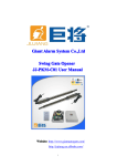
Quanzhou Giant Alarm System Co.LTD
Tel No.:
No.:(86-595)22499516
Fax No.:
No.:(86-595)22492516
Email:: [email protected]
Website:: www.cngiant.net
Automatic Barrier Gate Opener System
Installer and User
User’’s Manual
!
Automatic Barrier Gate Opener System is designed for vehicular traffic only!
CAUTION:
Automatic Barrier Gate Opener System is powerful while working. It may cause seriously
body injury or death to pedestrians if they walk through/around the automatic barrier
inappropriately. Should have other separate walkway for pedestrians.
1. Every time must cut off power supply before starting installation, operation or maintenance.
2. The Automatic Barrier System should be earthed and earth leakage breaker is necessary in
power supply.
3. Do not change the inside wirings.
4. If power cut occurs, please switch off the power supply at first, then opening door of cabinet
to open or close the barrier manually by rotating the handle.
5. The balance of the boom and spring already been well adjusted to optimum before out of the
factory. If it is not necessary, do not add the length or weight of boom in case of dangers
occurred. If the adjusting in necessary please ask your local dealers or installers.
6. All limit switches(both mechanical limit switch and photoelectric limit switch) already been
well adjusted to optimum. Do not adjust any limit switch unless it is necessary.
7. Keep the wireless control system (push-button, transmitters etc) out of the reach of children.
8. Use transmitters and push-button to control the automatic barrier only when you can see the
operation of the gate clearly.
9. Do not open the door or cover of cabinet when the motor is working.
10. Keep children away from the automatic barrier system.
1
Quanzhou Giant Alarm System Co.LTD
Tel No.:
No.:(86-595)22499516
Fax No.:
No.:(86-595)22492516
Email:: [email protected]
Website:: www.cngiant.net
1. Technical Specifications
Power Supply
AC220V±10%50HZ/60HZ or AC110V±10%50HZ/60HZ
Working Temperature
-20℃~55℃
Power of Motor
150W
Speed of Motor
1400r/m
Relative Humidity
≤90%
Max. Boom Length
6M
External Dimensions
103cm* 37cm * 31cm
Remote Control Distance
≤50M
Net Weight
50KG (not including the lever)
2. Installation and adjusting
Fig.1
2.1. Install the machine on the ground (Fig.1
Fig.1)
Fig.1
Fig.2-Fig.3
2.2. Install boom (Fig.2-Fig.3
Fig.2-Fig.3)
Fig.2
2
Quanzhou Giant Alarm System Co.LTD
Tel No.:
No.:(86-595)22499516
Fax No.:
No.:(86-595)22492516
Email:: [email protected]
Website:: www.cngiant.net
Fig.3
Fig.4
2.3. Manually Operation when power cut occurs (Fig.4
Fig.4)
If power cut occurs, please switch off the power supply at first, then opening door of cabinet to
open the barrier completely by rotating handle.
Rotating Handle
Fig.4
3
Quanzhou Giant Alarm System Co.LTD
Tel No.:
No.:(86-595)22499516
Fax No.:
No.:(86-595)22492516
Email:: [email protected]
Website:: www.cngiant.net
3. Adjust the limit switch (Fig.5)
All limit switches (both mechanical limit switch and photoelectric limit switch) already been well
adjusted to optimum. It can be adjusted by manually turning the limit leaf-blade.
Limit Switch
Limit Blade
Fig.5
4. Adjust Spring (Fig.6)
If the boom is shaking while if it falling down, use the wrench to tighten the nut of spring; if the
boom is shaking while rising up, use the wrench to loosen the nut of spring.
Spring
Adjusting Nut
Turning left to tighten the spring
Turning right to loosen the spring
Fig.6
4
Quanzhou Giant Alarm System Co.LTD
Tel No.:
No.:(86-595)22499516
Fax No.:
No.:(86-595)22492516
Email:: [email protected]
Website:: www.cngiant.net
5. Adjust Vertical or Horizontal Of the Boom
This already well adjusted to optimum before out of the factory. But it has to be re-adjusted if the
length of the boom changed.
Fig.7-Fig.8
5.1. Boom is shorter(Fig.7-Fig.8
Fig.7-Fig.8)
The boom will go upwards after it becomes shorter. Please note that our standard spring is
optmum for length of boom from 5M-6M. If the length of boom becomes short, the value of the
spring should be decreased.
Fig.7
Also can do the fine tuning to tune the verticle or horizontal of the boom.
Tuning Screw
Nut
Fig.8
5
Quanzhou Giant Alarm System Co.LTD
Tel No.:
No.:(86-595)22499516
Fax No.:
No.:(86-595)22492516
Email:: [email protected]
Website:: www.cngiant.net
Fig9-Fig10)
5.2. Boom is longer(Fig9-Fig10
The boom will go downwards after it becomes longer. Please note that our standard spring is
optimum for length of boom from 5M-6M. As the maximum length of the boom is 6M, so this
situation may not occur. Installer or user can add the value of spring according if it is necessary.
Fig.9
Also can do the fine tuning to tune the verticle or horizontal of the boom.
Tuning Screw
Nut
Fig.10
6
Quanzhou Giant Alarm System Co.LTD
Tel No.:
No.:(86-595)22499516
Fax No.:
No.:(86-595)22492516
Email:: [email protected]
Website:: www.cngiant.net
6. Wiring and Adjusting Electrical Part
Caution: Always cut off the power before doing any wiring or adjusting in
electrical part.
6.1. Wiring For Control Panel
P1
P2
Transformer
①:Transformer
Code Learning Button
②:Code
Working Times Potentiometer
③:Working
Jumper for motor reverse function
④:Jumper
Receiver Module Pluger
⑤:Receiver
6.3A Fuse
⑥:6.3A
External Push Button Pluger
⑦:External
Antenna Terminal
⑧:Antenna
7
Quanzhou Giant Alarm System Co.LTD
Tel No.:
No.:(86-595)22499516
Fax No.:
No.:(86-595)22492516
Email:: [email protected]
Website:: www.cngiant.net
P1
P2
Transformer
①:Transformer
Code Learning Button
②:Code
Working Times Potentiometer
③:Working
Jumper for motor reverse function
④:Jumper
Receiver Module Pluger
⑤:Receiver
6.3A Fuse
⑥:6.3A
External Push Button Pluger
⑦:External
Antenna Terminal
⑧:Antenna
L1
Boom opened
L7
Photo-cell.
L2
Boom closed
L8
Loop Detector
Code-learning
L9
Stop Status
Open Status
Close Status
L3
L4
Working Mode Switching
L10
L5
Downwards Limit Switch
L11
L6
Upwards Limit Switch
8
Quanzhou Giant Alarm System Co.LTD
Tel No.:
No.:(86-595)22499516
Fax No.:
No.:(86-595)22492516
Email:: [email protected]
Website:: www.cngiant.net
7. Transmitters
Transmitters’’ code setting
7.1. Transmitter programmed
Press “Code Learning” button, the code-learning LED indicator lights up, then press any button of
the transmitters which you are going it program till the code-learning LED indicator goes off.
Now the transmitter programmed. Other transmitters can be programmed as same as this way. It
can program up to 30 transmitters.
7.2. Transmitters’ code removing
Press and hold code-learning button for 5 seconds, the code-learning LED flashes 5 times, all the
programmed transmitters removed.
7.3. Working Mode Switching
。
It refers to when you use wireless remote control to operate the barrier gate. There are two types of
working mode: three buttons working mode or single button working mode. In the three buttons
working mode, for example, button “A” operates “open” button “B” operates “stop” and
button “C” operates “close”. In the single button working mode, there is only one button works
cycle-operation “open-stop-close”. It can be switched as per users’ preferences by using wire to
short-circuit the terminal “mode” and “com” (see fig), about 5 seconds later, the LED indicator
flashes, the working mode has been switched.
8. Safety Devices(Optional)
8.1. Photocell
When the gate is open, if any objects or persons sensed in the sensing range of photocell, the gates
keep open status.
9
Quanzhou Giant Alarm System Co.LTD
Tel No.:
No.:(86-595)22499516
Fax No.:
No.:(86-595)22492516
Email:: [email protected]
Website:: www.cngiant.net
When the gate is close, if any objects or persons sensed in the sensing range of photocell, the gates
will open immediately.
8.2. Loop Detector
If any objects or persons sensed in the sensing range, the gate keeps open status.
After the objects or persons pass through the range of sensing range, the gate will close
immediately.
10
Quanzhou Giant Alarm System Co.LTD
Tel No.:
No.:(86-595)22499516
Fax No.:
No.:(86-595)22492516
Email:: [email protected]
Website:: www.cngiant.net
Note: If auto-closing function is enabled, when the objects or persons pass through sensing
range, the gate will close automatically after reaching the delay time which set earlier. The
delay time can be set from 1—99 seconds.
9. Trouble Shooting
Problem
Possible causes
Repair method
1.Check the motor wiring connection is
1.Check the motor wiring is
correct or not
strong and reliable
2.Check
each
limit
connection
is
2.Correct wiring connection
correct or not
from motor to control panel is
3.Check the capacitor connect up or
red (UP),white(COM),yellow
Motor
works
but
not.
(DOWN).Limit wiring: black
boom do not work
(COM),orange(DOWN),green
(UP),red (5VDC)
3.Connect
two
capacitor
wirings with motor wirings for
up and down.
1.
Please
replace
spring
according spring list and adjust
1.Spring is out of balance
Boom
vibrates
too
spring in a best level.
2.Boom screws is loose.
much during falling.
2. Fasten screws in the boom.
3.Barrier house do not been fixed well.
3.Fasten fang bolt for fixing
barrier house
1.Check
the limit wire then
Boom stops in the
1.Not adjust limit switch well
connect in a right place and
middle during falling.
2.Spring is out of force
adjust limit switch
11
Quanzhou Giant Alarm System Co.LTD
Tel No.:
No.:(86-595)22499516
Fax No.:
No.:(86-595)22492516
Email:: [email protected]
Website:: www.cngiant.net
2.Replace spring or adjust
spring force.
Replace loop detector and
Without anti-break
Loop detector and photocell broken or photocell,then
no connection in a right place
wire
connect
carefully
the
according
wiring diagram
Make the boom in vertical or
horizontal level,then put the
light barrier in the middle of
Boom
is
not
in
the photoelectric limit switch
vertical or horizontal
Not adjust the limit well
since
light
is
on
during
level when up and
induction . Boom is down in
down
place
when
Red
light
is
on ,and up in place when green
light is on.
12