1
Smart actuator module for legged robots
AI MOTOR-701 MANUAL
Ver 1.02
Thank you for your purchasing our product.
to use AI MOTOR-701 neatly.
This manual shows how
Before using your AI MOTOR-701,
please read this manual carefully.
MEGAROBOTICS LTD.
w w w .m egarobotics.com
CONTENTS
1. Introduction
1.1. Summary
1.2. Package contents
1.3. Names of parts
1.4. Functions
1.5. Features and specifications
3
3
4
5
6
2. Detailed Description and Usage
2.1. Hardware interface
2.2. Mechanical interface
2.3. Software interface
2.4. Position control function
8
12
14
23
3. Appendix
3.1. RS-232 board
3.2. Examples of baud-rate for MCUs
3.3. Application examples of AI MOTOR
3.4. Example of program(1)
3.5. Example of program(2)
24
25
28
29
35
1. INTRODUCTION
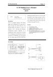
1.1. Summary
AI MOTOR-701 is a actuator module for legged robots that can assemble and
control various types of robots. Motors are essential for all the moving devices.
However, it is not available for general people since special devices and a lot
of money are required in control, electronic circuit, and connection and
combination of parts. AI MOTOR-701 integrates motors, members and control
circuits in one module so as to easily connect them to one another.
Accordingly, if you use the product, you can design joints of a moving device
simply and it is easy to expand the device additionally and to cope with
troubles of the device. It is possible to connect motors to each other serially so
as to simplify wiring. Control commands can be delivered once through a widely
used RS-232 serial communication. Operation of motors can be monitored since
AI MOTOR-701 has a function of outputting the amount of the current flowing in
the motor and position of the motor.
The operation modes are 360 degrees rotation mode, 0 to 332 degrees range
position control mode, act down mode in which position change of the shaft of
the motor can be monitored using external force by making torque of the shaft
of the motor be zero, power down mode in which power consumption is
minimized, synchronous position control mode.
The internal parameters of the motor can be changed by a program through
serial communication. The changeable parameters are ID of the motor, baud-rate
of the serial communication, position control resolution, position control gain,
threshold of over-current, upper bound, lower bound. AI MOTOR-701 internally
confirms external power and controls internal control gain automatically so that
constant control response is ensured though input voltage varies. It protects the
motor against being damaged by cut off the motor current automatically when
the current flowing in the motor is too much, where the threshold of over-current
can be changed.
11 types of connecting parts are provided so as to assemble parts in various
directions when connecting motors to each other. And also, since there are two
shafts of the motor, it is very convenient to connect joints.
1.2. Package Contents
① AI MOTOR
② Cable 100mm
Cable 150mm
③ Joint parts (11 pieces)
④ Bolt M1.7 × 8 mm
Bolts M2.0 × 12 mm (2 pieces)
Bolts M2.0 × 16 mm (2 pieces)
Nuts M2.0 (4 pieces)
⑤ Spare gear 2
Spare gear 3
Figure 1. Package contents
1.3. Names of Parts
Dissembled view of body
Figure 2. Dissembled view of body
Joint parts
Table 1. Usage of Joints
Usage
Joint part number
Shaft ↔ Body connection
1, 3, 6
Shaft ↔ Shaft connection
2, 10
Body ↔ Body connection
4, 8
Miscellaneous connection
5, 7, 9, 11
Figure 3. 11 types of Joints
Cable
Cable to connect motors to each other or connect a motor to a control
board. Length are 10 cm, 15 cm respectively.
Figure 4. Cable
1.4. Functions
Position control function
Low resolution mode (0 to 332 degrees), High resolution mode (0 to 166
degrees)
Sensor function
Feedback of Current (8 bit) and Position (8 bit)
Speed control function
Position send mode 5 steps, 360 degrees rotation mode 16 steps
Resolution adjustment function (2 steps)
Low resolution 1.3 degrees, High resolution 0.65 degree
360 degrees rotation function (wheel operation mode)
Synchronous position control function
Position control of AI MOTORs start at the same time
Bound setting function
Position range of the shaft
Reverse voltage protection
0 to -28 V
Over-current protection
Settable range
400 to 1000 mA
Parameter setting function
ID, Baud-rate, resolution, threshold of over-current, P-gain, D-gain
Voltage sensing function
Internal control gain is set automatically depending on Input voltage
(DC 5 to 10 V)
Mechanical direct connection between modules
Various connections are possible using 2 output shafts, body joint part and
11 types of joint parts.
Electrical direct connection between modules
Electrical direct connection are possible using two connector terminals and
a connector cable.
Control signal I/O by communication
A full-duplex UART is built-in. The motors are controlled in RS-232 serial
communication. 31 motors can be connected and controlled in one channel
1.5. Features and specifications
Advantages
-
High performance to price
Excellent assembly between motors
Good gear endurance
Various operation modes supplied
Test tool program supplied
Various application program supplied
Size
Figure 5. Size of Body
unit : mm
Specifications
Table 2. Specifications of AI MOTOR-701
Standards
Communication
Capability of Connection
ID
Parameter
Range
RS-232 asynchronous serial communication
(TTL level)
Maximum 31 per one communication channel
0 to 30
Baud-rate
2400 to 460800 bps
Resolution
Low Resolution (1.3 degrees) or High Resolution
(0.65 degree)
P-Gain
Recommended 1 to 50
D-Gain
Recommended 0 to 100
Threshold of Over-current
Approximate 400 mA to 1000 mA
Lower bound, Upper bound 0 <= Lower bound < Upper bound <= 254
Operation
Maximum Torque
Approximate 7 Kg・cm (at +9.5 V)
Maximum Speed
Approximate 82 rpm (at +9.5 V)
Low resolution mode : 333.3/255 ≒ 1.307 degrees
High resolution mode : 166.65/255 ≒ 0.654 degree
Minimum Angle
Operation
Mode
Speed Mode
(Fastest)
Position Speed Mode
Send
Speed Mode
Mode
Speed Mode
Speed Mode
(Slowest)
Position Read Mode
0
1
2
3
4
Act Down Mode
(Position Sensor Mode)
Power Down Mode
System
Protection
360 degrees Rotation
Mode
Synchronous Position
Control Mode
Limitation of Over-current
Inverse Voltage Protection
Motor
Electrical
Types
The present current and position are informed of.
The present current and position are informed of,
torque of the motor is removed, and the motor is
moved by the external force.
Power down state is maintained without torque of
the motor until another command is received.
16 steps speed control(0: stop, 1: min, 15: max)
Position control of AI MOTORs start at the same
time
Approximate 400 to 1000 mA (settable by user)
0 to -28 V
DC precious metal brush motor
Maximum Current 650 mA at DC 5V, 1000 mA at DC 10 V
Input Voltage
High(2.57 to 5.2V), Low(-0.5 to 0.94V)
Level
Control
Output Voltage
High(3.25 to 4.7V ), Low(0 to 0.6V)
Circuit
Level
11.7 mA in general mode, 11.6 mA in power down
Current
mode
Connecting Parts
11 types (Plastic)
Size(Max.)
Mechanical
The present current and position are informed of
and it moves to a specific position
Weight
51.6 × 34.3 × 37.1 mm
40 g
Mutual Connecting Points
3 places
Gear Ratio
1 : 173
Gear Material
Plastic
Block diagram
Vcc
GND
Reverse
Voltage
Protector
Regulator
LC Filter
PW M
Tx
Tx
Rx
Rx
Voltage
Detector
M otor
Direction
M otor
Driver
MPU
Gear
Voltage
A/D
Current
A/D
Position
A/D
Current
Rotary
Detector
Sensor
Figure 6. Block diagram of AI MOTOR-701
2. Detailed Description and Usage
2.1. Hardware interface
Power supply and signal line used in a connector that is hardware interface of
AI MOTOR will be described from now on.
Connector
AI MOTOR body has two connectors. Two connectors are connected to
each other in parallel internally. You can use AI MOTOR if you connect
any one of the two connectors. The other connector is used to connect
another module in serial.
Connector 1
Connector 2
1: Ground, 2: RXD of AI MOTOR, 3: TXD of AI MOTOR, 4: Vcc
Figure 7. Connector
Electrical characteristics
Table 3. Maximum Operating Conditions
Symbol
VCC
ICC
VIL
VIH
VOL
VOH
TO
TS
Parameter
Supply Voltage
Operation Current
Input Low Voltage
Input High Voltage
Output Low Voltage
Output High Voltage
Operating Temperature
Storage Temperature
Min.
4.5
11.6
-0.5
2.57
0
3.25
0
-40
Max.
10.5
1015
0.94
5.2
0.6
4.7
70
120
Unit
V
mA
V
V
V
V
℃
℃
Max.
9
600
1.2
5.2
0.6
4.7
40
80
Unit
V
mA
V
V
V
V
℃
℃
Table 4. Recommended Operating Conditions
Symbol
VCC
ICC
VIL
VIH
VOL
VOH
TO
TS
Parameter
Supply Voltage
Operation Current
Input Low Voltage
Input High Voltage
Output Low Voltage
Output High Voltage
Operating Temperature
Storage Temperature
Min.
5.5
-0.5
3.29
0
4.0
10
-40
Power On Reset
No commands are received for 65 ms after turned on.
operating in act down mode.
Reset Delay : 65ms
Power On
After that,
Nominal Operating(Act Down Mode)
Figure 8. Sequence of Power On Reset
RS-232 signal timing
Control commands and data are transmitted and received in asynchronous
RS-232 communication of TTL level. At over 115200 bps, it need delay
time over 150 us within the stop bit of a byte and the start bit of the next
byte. At under 57600 bps, it need no delay time.
RX, TX
Start
D0
D1
D2
D3
D4
D5
Bit
D6
D7
Stop
Bit
Figure 9. Signal Timing of RS-232 communication
RS-232 communication delay
Since AI MOTOR-701 receives commands in RS-232 communication, all
the motors do not receive commands at the same time in the case that a
few modules are connected and the motors are controlled.
Although
communication delay is usually negligible, consider communication delay
time shown in the following table and use AI MOTOR-701.
Table 5. Delay Time of Communication
Baud-rate 1 byte transmission 1 command (4 bytes) 1 command delay angle
[bps]
time [ms]
transmission time [ms]
[Deg.] at 30 rpm
2400
4.167
16.667
3
4800
2.083
8.333
1.5
9600
1.042
4.167
0.75
19200
0.521
2.083
0.375
38400
0.260
1.042
0.1875
57600
0.174
0.694
0.0125
115200
0.087
0.347
0.0625
153600
0.065
0.260
0.046875
230400
0.043
0.174
0.03125
460800
0.022
0.087
0.015625
Response time
Table 7. shows the elapsed time after sending of command packet until
receiving the response packet at various baud-rate.
Table 7. Response time(max.)
[unit : uS]
baudrate
command
2400
bps
4800
bps
9600
bps
19200
bps
38400
bps
57600 115200
bps
bps
Position Send
25329
13159
7083
4045
2517
1354
1180
Position Read
25329
13159
7083
4045
2517
1354
1180
Act Down
25329
13159
7083
4045
2517
1354
1180
Power Down
25329
13159
7083
4045
2517
1354
1180
360 degrees
Rotation
25329
13159
7083
4045
2517
1354
1180
Gain Read
33662
17326
9166
5086
3038
1701
1354
Resolution
Read
Overcurrent
threshold read
33662
17326
9166
5086
3038
1701
1354
33662
17326
9166
5086
3038
1701
1354
Bound Read
33662
17326
9166
5086
3038
1701
1354
Baudrate Set
153453 136144 127950 124877 122829 121492 121145
Gain Set
153453 136144 127950 124877 122829 121492 121145
ID Set
153453 136144 127950 124877 122829 121492 121145
Resolution
Set
Overcurrent
threshold set
Bound Set
153453 136144 127950 124877 122829 121492 121145
153453 136144 127950 124877 122829 121492 121145
153453 136144 127950 124877 122829 121492 121145
Position control response
Since control gain is set automatically owing to automatical voltage sensing
function, it does not over-shoot though input voltage is raised up.
※ Conditions of Experiment
- Initial position
:
- Target position
:
- Load
:
- Measuring time
:
- Number of samples
:
15
165
0
2 seconds
80
(a) Input Voltage = 5.5V
(b) Input Voltage = 9.5V
Figure 10. Response of Position Send Command
2.2. Mechanical interface
The usage of a body joint part, an output shaft and a joint part which are
mechanical parts of AI MOTOR will be taught.
Types and examples of joint parts
Table 6. Usage of Joints
Joint parts
JOINT 1
JOINT 2
JOINT 3
JOINT 4
JOINT 5
Assembly forms
Assembled appearances
Joint parts
JOINT 6
JOINT 7
JOINT 8
JOINT 9
JOINT 10
JOINT 11
Assembly forms
Assembled appearances
2.3. Software interface
Communication protocol that is software interface of AI MOTOR will be
described.
2.3.1. Communication flow
All the communication commands flow as illustrated in the following figure.
When a controller sends a command packet to AI MOTOR, AI MOTOR returns
a response packet to the controller.
Command packet
Controller
Response packet
Figure 11. Flow of Communication
2.3.2. Command Packet
There are two kinds of command packets, that is, an operation command packet
and a setting command packet (6 bytes).
2.3.2.1. Operation Command Packet
Position Send Command
Command to return to the other controller the present current of AI
MOTOR and the present position of output shaft, and move to a desired
location. The speed can be controlled in 5 levels.
▶ Command Packet
1byte
1byte
1byte
1byte
Header
Data1
Data2
Checksum
- Header
= 0xFF(Packet start)
- Data1
=
7
Speed
6
5
4
3
ID
2
1
※ Speed
: 0(fastest)~4(slowest)
ID
: 0~30
- Data2
= 0~254(Target position)
- Checksum = (Data1 XOR Data2) AND 0x7F
▶ Response Packet
1 byte
1 byte
Current
Position
- Current
- Position
= approximate 18.4 mA per 1
= 0~255
0
bit number
Position Read Command
Command to return the present current of AI MOTOR and the present
position of output shaft
▶ Command Packet
1byte
1byte
1byte
1byte
Header
Data1
Data2
Checksum
- Header
= 0xFF(Packet start)
- Data1
=
5 (=0b101)
7
6
5
4
3
ID
2
1
0
bit number
※ ID
: 0~30
- Data2
= arbitrary
- Checksum = (Data1 XOR Data2) AND 0x7F
▶ Response Packet
1 byte
1 byte
Current
Position
- Current
- Position
= approximate 18.4 mA per 1
= 0~255
Act Down Command
Command to send the present position of output shaft and remove torque
of the motor to move due to external force.
▶ Command Packet
1byte
1byte
1byte
1byte
Header
Data1
Data2
Checksum
- Header
= 0xFF(Packet start)
- Data1
=
6 (=0b110)
7
6
5
※ ID
- Data2
=
7
4
3
ID
2
3
Arbitrary
2
1
- Checksum = (Data1 XOR Data2) AND 0x7F
▶ Response Packet
1 byte
Data2
Position
- Position
= 0~255
0
bit number
0
bit number
: 0~30
1 (=0b0001)
6
5
4
1 byte
1
Power Down Command
All the connected AI MOTORs are powered down. If a communication
command is received, AI MOTORs are awakened.
Command to send the present position of output shaft and remove torque
of the motor to move due to external force.
▶ Command Packet
1byte
1byte
1byte
1byte
Header
Data1
Data2
Checksum
- Header
= 0xFF(Packet start)
- Data1
=
6 (=0b110)
7
6
5
- Data2
=
7
4
31 (=0b11111)
3
2
1
0
2 (=0b0010)
6
5
4
3
Arbitrary
2
1
0
bit number
bit number
- Checksum = (Data1 XOR Data2) AND 0x7F
▶ Response Packet
1 byte
1 byte
ID
Position
360 degrees Rotation Command
Command to rotate the shaft of AI MOTOR by 360 degrees. Its speed can
be controlled in 16 levels.
▶ Command Packet
1byte
1byte
1byte
1byte
Header
Data1
Data2
Checksum
- Header
= 0xFF(Packet start)
- Data1
=
6 (=0b110)
7
6
5
※ ID
- Data2
=
7
4
3
ID
2
1
0
bit number
3
Speed
2
1
0
bit number
: 0~30
Direction
6
5
4
※ Direction
: 3(CCW), 4(CW)
Speed
: 0(stop), 1(min)~15(max)
- Checksum = (Data1 XOR Data2) AND 0x7F
▶ Response Packet
1 byte
1 byte
Rotations
Position
- Rotations
- Position
= 0~255(rotations after power-on, ○
+ : CCW, ○
- : CW)
= 0~255
Synchronous Position Send Command
Command to control several AI MOTORs at the same time. The speed
can be controlled in 5 levels.
▶ Command Packet
1byte
1byte
1byte
1byte
Header
Data1
Last ID+1
Pos[0]
1byte
Pos[Last ID] Checksum
- Header
= 0xFF(Packet start)
- Data1
=
- Last ID
- Pos[0]
※ Speed
: 0(fastest)~4(slowest)
= 0~30(ID of the last AI MOTOR)
= 0~254(Target position of the ID 0)
7
Speed
6
5
4
1byte
31 (=0b11111)
3
2
1
0
bit number
- Pos[Last ID]= 0~254(Target position of the Last ID)
XOR Pos[Last ID]) AND 0x7F
- Checksum = (Pos[0] XOR Pos[1]
▶ Response Packet
- none
2.3.2.2. Setting command packet (6 bytes)
Baud-rate Set Command
Command to set the Baud-rate of AI MOTOR. Supplied Baud-rate is 2400,
4800, 9600, 19200, 38400, 57600, 115200, 230400, 307200 and 460800
bps.
▶ Command packet
1byte
1byte
1byte
1byte
1byte
1byte
Header
Data1
Data2
Data3
Data4
Checksum
- Header
= 0xFF(Packet start)
- Data1
=
7 (=0b111)
7
6
5
4
3
ID
2
1
0
bit number
※ ID : 0~30
- Data2
= 0x08
- Data3
= 0(460800bps), 1(230400bps), 2(153600bps),
3(115200bps), 7(57600bps), 11(38400bps), 23(19200bps),
47(9600bps), 95(4800bps), 191(2400bps)
- Data4
= Data3
- Checksum = (Data1 XOR Data2 XOR Data3 XOR Data4) AND 0x7F
▶ Response packet
1 byte
New
Baud-rate
1 byte
New
Baud-rate
- New Baud-rate
= 0~191
Control Gain Set Command
Command to set the control gains of AI MOTOR. The settable control
gains are proportional gain and differentiating gain.
▶ Command packet
1byte
1byte
1byte
1byte
1byte
1byte
Header
Data1
Data2
Data3
Data4
Checksum
- Header
= 0xFF(Packet start)
- Data1
=
7 (=0b111)
7
6
5
4
3
ID
2
1
0
bit number
※ ID : 0~30
- Data2
= 0x09
- Data3
= recommended 1~50(New P-gain)
- Data4
= recommended 0~100(New D-gain)
- Checksum = (Data1 XOR Data2 XOR Data3 XOR Data4) AND 0x7F
▶ Response packet
1 byte
1 byte
New P-gain New D-gain
- New P-gain
- New D-gain
= 1~50
= 0~100
ID Set Command
Command to set the ID of AI MOTOR.
▶ Command packet
1byte
1byte
1byte
1byte
1byte
1byte
Header
Data1
Data2
Data3
Data4
Checksum
- Header
= 0xFF(Packet start)
- Data1
=
7 (=0b111)
7
6
5
4
3
ID
2
1
0
bit number
※ ID : 0~30
- Data2
= 0x0A
- Data3
= 0~30(New ID)
- Data4
= Data3
- Checksum = (Data1 XOR Data2 XOR Data3 XOR Data4) AND 0x7F
▶ Response packet
1 byte
1 byte
New ID
New ID
- New ID
= 0~30
Control Gain Read Command
Command to read the control gain of AI MOTOR.
▶ Command packet
1byte
1byte
1byte
1byte
1byte
1byte
Header
Data1
Data2
Data3
Data4
Checksum
- Header
= 0xFF(Packet start)
- Data1
=
7 (=0b111)
7
6
5
4
3
ID
2
1
0
bit number
※ ID : 0~30
- Data2
= 0x0C
- Data3
= arbitrary
- Data4
= arbitrary
- Checksum = (Data1 XOR Data2 XOR Data3 XOR Data4) AND 0x7F
▶ Response packet
1 byte
1 byte
P-gain
D-gain
- P-gain
- D-gain
= 1~50
= 1~100
Resolution Set Command
Command to set the resolution of AI MOTOR.
▶ Command packet
1byte
1byte
1byte
1byte
1byte
1byte
Header
Data1
Data2
Data3
Data4
Checksum
- Header
= 0xFF(Packet start)
- Data1
=
7 (=0b111)
7
6
5
4
3
ID
2
1
0
bit number
※ ID : 0~30
- Data2
= 0x0D
- Data3
= 0(Low resolution), 1(High resolution)
- Data4
= Data3
- Checksum = (Data1 XOR Data2 XOR Data3 XOR Data4) AND 0x7F
▶ Response packet
1 byte
New
Resolution
1 byte
New
Resolution
- New Resolution
= 0(Low resolution), 1(High resolution)
Resolution Read Command
Command to read the resolution of AI MOTOR.
▶ Command packet
1byte
1byte
1byte
1byte
1byte
1byte
Header
Data1
Data2
Data3
Data4
Checksum
- Header
= 0xFF(Packet start)
- Data1
=
7 (=0b111)
7
6
5
4
3
ID
2
1
0
bit number
※ ID : 0~30
- Data2
= 0x0E
- Data3
= arbitrary
- Data4
= arbitrary
- Checksum = (Data1 XOR Data2 XOR Data3 XOR Data4) AND 0x7F
▶ Response packet
1 byte
1 byte
Resolution
Resolution
- Resolution = 0(Low resolution), 1(High resolution)
Threshold of Over-Current Set Command
Command to set the threshold of over-current of AI MOTOR.
※ Note : If over-current occurred, it would be act-down mode.
▶ Command packet
1byte
1byte
1byte
1byte
1byte
1byte
Header
Data1
Data2
Data3
Data4
Checksum
- Header
= 0xFF(Packet start)
- Data1
=
7 (=0b111)
7
6
5
4
3
ID
2
1
0
bit number
※ ID : 0~30
= 0x0F
= 22~54 (=Coefficient × threshold of over-current in mA)
ex) 22 ≒ 0.054468085 × 403.9 mA
- Data4
= Data3
- Checksum = (Data1 XOR Data2 XOR Data3 XOR Data4) AND 0x7F
▶ Response packet
- Data2
- Data3
1 byte
1 byte
New
New
Threshold of Threshold of
Over-current Over-current
- New Threshold of Over-current
= 22~54 (=Coefficient × threshold of over-current in mA)
Threshold of Over-Current Read Command
Command to read the threshold of over-current of AI MOTOR.
▶ Command packet
1byte
1byte
1byte
1byte
1byte
1byte
Header
Data1
Data2
Data3
Data4
Checksum
- Header
= 0xFF(Packet start)
- Data1
=
7 (=0b111)
7
6
5
4
3
ID
2
1
0
bit number
※ ID : 0~30
- Data2
= 0x10
- Data3
= arbitrary
- Data4
= arbitrary
- Checksum = (Data1 XOR Data2 XOR Data3 XOR Data4) AND 0x7F
▶ Response packet
1 byte
1 byte
Threshold of Threshold of
Over-current Over-current
Bound Set Command
Command to set the upper bound and the lower bound of the position
range
▶ Command packet
1byte
1byte
1byte
1byte
1byte
1byte
Header
Data1
Data2
Data3
Data4
Checksum
- Header
= 0xFF(Packet start)
- Data1
=
7 (=0b111)
7
6
5
4
3
ID
2
1
0
bit number
※ ID : 0~30
- Data2
= 0x11
- Data3
= 0~254(Minimum position)
- Data4
= 0~254(Maximum position)
- Checksum = (Data1 XOR Data2 XOR Data3 XOR Data4) AND 0x7F
▶ Response packet
1 byte
New lower
bound
1 byte
New upper
bound
Bound Read Command
Command to read the upper bound and the lower bound of the position
range
▶ Command packet
1byte
1byte
1byte
1byte
1byte
1byte
Header
Data1
Data2
Data3
Data4
Checksum
- Header
= 0xFF(Packet start)
- Data1
=
7 (=0b111)
7
6
5
4
3
ID
2
1
0
bit number
※ ID : 0~30
- Data2
= 0x12
- Data3
= arbitrary
- Data4
= arbitrary
- Checksum = (Data1 XOR Data2 XOR Data3 XOR Data4) AND 0x7F
▶ Response packet
1 byte
Lower
bound
1 byte
Upper
bound
2.4. Position Control Function
When a user send his or her desired absolute position in the range of 0 to
254, the shaft of AI MOTOR is moved to the desired position. The position
control function is executed by the 'Position Send Command'. Here, notice that
the absolute position depends on the resolution.
Low Resolution Mode
Position control range is 0 to 332 degrees.
degrees.
Position 0
Position 128
Unit angle is about 1.307
Position 254
Figure 12. Position in Low Resolution Mode
※ Note : When Joint 1 or 2 or 10 be combined, it can be move in
66 ~ 207.
When Joint 6 was combined, it can be move in 43 ~ 186 or
86 ~ 229.
High Resolution Mode
Position control range is 0 to 166 degrees.
degree.
Position 0
Position 128
Figure 13. Position in High Resolution Mode
Unit angle is about 0.654
Position 254
3. Appendix
3.1. RS-232 board
RS-232 board adjusts a signal level when connecting AI MOTOR to PC or
another controller. Figure 14 illustrates connecting AI MOTOR to PC by using
RS-232 board.
TTL level
RS-232 level
RS-232
board
PC
Figure 14. Function of RS-232 board
Figure 15. Connection of AI MOTORs to a PC
+5V
VCC
C1
1uF
C2
1uF
16
C3
1uF
C5
1uF
SW1
1
3
2
4
5
6
VCC
1
4
1
2
2
U1
5
3
1
2
Battery_pack
Txd
Rxd
POWER
1uF
11
14
10
7
Rxd
12
13
RX_of_PC
Txd
Rxd
VCC
VCC
1
2
3
4
Txd
Rxd
U2
C6
10uF
LP2985
CR1
LED
C8
10uF
Txd
Rxd
VCC
1
2
3
4
5
6
7
8
HEADER8B
VCC
1
2
3
4
5
6
7
8
HEADER8B
5
4
C7
103
VCC
CN5
Txd
Rxd
VIN
VOUT
GND
BP
SD
Txd
Rxd
CN4
5
6
7
8
VCC
3
5
6
7
8
HEADER8B
CN3
Txd
Rxd
+5V
2
VCC
CN2
1
2
3
4
1
2
3
HEADER8B
1
Txd
Rxd
Power_supply
MAX232
VCC
VCC
TX_of_PC
8
15
9
5
6
7
8
HEADER8B
C4
Txd
VCC
CN1
1
2
3
4
R1
470
Figure 16. Schematic of RS-232 board
CN7
Txd
Rxd
RX_of_PC
TX_of_PC
1 1
2 2
3 3
PC
Txd
Rxd
3.2. Examples of baud-rate for MCUs
We recommend the following configuration that minimize communication error.
MCS51 Family(Timer1 use, Mode1)
Clock[Mhz]
7.3728
7.3728
7.3728
7.3728
7.3728
7.3728
7.3728
7.3728
7.3728
11.0592
11.0592
11.0592
11.0592
11.0592
11.0592
11.0592
11.0592
14.7456
14.7456
14.7456
14.7456
14.7456
14.7456
14.7456
14.7456
14.7456
14.7456
22.1184
22.1184
22.1184
22.1184
22.1184
22.1184
22.1184
22.1184
22.1184
22.1184
22.1184
22.1184
SMOD
0
1
0
1
0
1
0
1
1
0
1
0
1
0
1
1
1
0
1
0
1
0
1
0
1
0
1
0
1
0
1
0
1
0
1
1
0
1
1
TH1
248
240
252
248
254
252
255
254
255
244
232
250
244
253
250
253
255
240
224
248
240
252
248
254
252
255
254
232
208
244
232
250
244
253
250
253
255
254
255
Baud-rate[bps]
2400
2400
4800
4800
9600
9600
19200
19200
38400
2400
2400
4800
4800
9600
9600
19200
57600
2400
2400
4800
4800
9600
9600
19200
19200
38400
38400
2400
2400
4800
4800
9600
9600
19200
19200
38400
57600
57600
115200
Error[%]
0
0
0
0
0
0
0
0
0
0
0
0
0
0
0
0
0
0
0
0
0
0
0
0
0
0
0
0
0
0
0
0
0
0
0
0
0
0
0
80c196Kx(Mode1)
Clock[Mhz]
7.3728
7.3728
7.3728
7.3728
7.3728
7.3728
7.3728
11.0592
11.0592
11.0592
11.0592
11.0592
11.0592
11.0592
11.0592
14.7456
14.7456
14.7456
14.7456
14.7456
14.7456
14.7456
14.7456
SP_BAUD
80BF
805F
802F
8017
800B
8007
8003
811F
808F
8047
8023
8011
800B
8005
8002
817F
80BF
805F
802F
8017
800F
8007
8003
Baud-rate[bps]
2400
4800
9600
19200
38400
57600
115200
2400
4800
9600
19200
38400
57600
115200
230400
2400
4800
9600
19200
38400
57600
115200
230400
Error[%]
0
0
0
0
0
0
0
0
0
0
0
0
0
0
0
0
0
0
0
0
0
0
0
PIC Family
Clock[Mhz]
3.6864
3.6864
3.6864
3.6864
3.6864
7.3728
7.3728
7.3728
7.3728
7.3728
7.3728
7.3728
11.0592
11.0592
11.0592
11.0592
11.0592
14.7456
14.7456
14.7456
14.7456
14.7456
14.7456
14.7456
BRGH
0
0
0
0
0
0
0
0
0
0
0
0
0
0
0
0
0
0
0
0
0
0
0
0
SPBRG
23
11
5
2
0
47
23
11
5
2
1
0
71
35
17
8
2
95
47
11
5
3
1
0
Baud-rate[bps]
2400
4800
9600
19200
57600
2400
4800
9600
19200
38400
57600
115200
2400
4800
9600
19200
57600
2400
4800
19200
38400
57600
115200
230400
Error[%]
0
0
0
0
0
0
0
0
0
0
0
0
0
0
0
0
0
0
0
0
0
0
0
0
AVR Family
Clock[Mhz]
7.3728
7.3728
7.3728
7.3728
7.3728
7.3728
7.3728
7.3728
7.3728
14.7456
14.7456
14.7456
14.7456
14.7456
14.7456
14.7456
14.7456
14.7456
UBRRH
0
0
0
0
0
0
0
0
0
1
0
0
0
0
0
0
0
0
UBRRL
191
95
47
23
11
7
3
1
0
127
191
95
47
23
15
7
3
1
Baud-rate[bps]
2400
4800
9600
19200
38400
57600
115200
230400
460800
2400
4800
9600
19200
38400
57600
115200
230400
460800
Error[%]
0
0
0
0
0
0
0
0
0
0
0
0
0
0
0
0
0
0
3.2. Application examples of AI MOTOR
Figure 17. 4-legged robot
Figure 18. Humanoid robot
Figure 19. A Pan-tilt structure using 2 AI-motors
3.4. Example of program(1)
This is an example of program in pseudo C code. Because The function of
serial communication depends on the CPU, you should modify the serial
functions.
/*============================================================================*/
/* AI MOTOR example code
*/
/* description : If you move the shaft, the shaft rotate the same direction
*/
/*
and stop.
*/
/* principal : Using position feed back function of AI MOTOR, the program
*/
/*
detect the variation of position and direction
*/
/*============================================================================*/
#define HEADER
0xff
#define NULL
0
#define ROTATE_CCW
3
#define ROTATE_CW 4
#define TIME_OUT1
35 //Max.response time of operation command is about 35ms
#define TIME_OUT2
155 //Max.response time of setting command is about 155ms
/* Function prototype start --------------------------------------------------*/
/*--------------- Serial communication functions (CPU dependent) -------------*/
void SendByte(char data);
// Send a byte to serial port
void GetByte(char timeout); // Receive a byte from serial port
/*-------------------------- AI-Motor functions ------------------------------*/
void SendOperCommand(char Data1, char Data2);
void SendSetCommand(char Data1, char Data2, char Data3, char Data4);
char PosSend(char ServoID, char SpeedLevel, char Position);
char PosRead(char ServoID);
char ActDown(char ServoID);
char PowerDown(void);
char Rotation360(char ServoID, char SpeedLevel, char RotationDir);
void SyncPosSend(char LastID, char SpeedLevel, char *TargetArray, char Index);
char BaudrateSet(char ServoID, char NewBaud);
char GainSet(char ServoID, char *NewPgain, char *NewDgain);
char IdSet(char ServoID, char NewId);
char GainRead(char ServoID, char *Pgain, char *Dgain);
char ResolSet(char ServoID, char NewResol);
char ResolRead(char ServoID);
char OverCTSet(char ServoID, char NewOverCT);
char OverCTRead(char ServoID);
char BoundSet(char ServoID, char *NewLBound, char *NewUBound);
char BoundRead(char ServoID, char *LBound, char *UBound);
/*---------------------------------------------------- Function prototype end */
void main(void)
{
char i, old_position;
Initialize();
// peripheral initialization
id = 0;
old_position = ActDown(id);
// ID 0 position read firstly
while(1) {
now_position = ActDown(id); // get now position
if(now_position<old_position) {
// if the position decreased
Rotation360(id, 10, ROTATE_CCW);
delay_ms(1000);
ActDown(id);
delay_ms(1000);
}
}
}
else if(now_position>old_position){// if the position increased
Rotation360(id, 10, ROTATE_CW);
delay_ms(1000);
ActDown(id);
delay_ms(1000);
}
old_position = ActDown(id);
// memory position
delay_ms(300);
////////////////////////// Function declaration start //////////////////////////
/******************************************************************************/
/* Send an operation command(4byte) to AI-motor
*/
/* Input : Data1, Data2
*/
/* Output : None
*/
/******************************************************************************/
void SendOperCommand(char Data1, char Data2)
{
char CheckSum;
CheckSum = (Data1^Data2)&0x7f;
SendByte(HEADER);
SendByte(Data1);
SendByte(Data2);
SendByte(CheckSum);
}
/******************************************************************************/
/* Send a setting command(6byte) to AI-motor
*/
/* Input : Data1, Data2, Data3, Data4
*/
/* Output : None
*/
/******************************************************************************/
void SendSetCommand(char Data1, char Data2, char Data3, char Data4)
{
char CheckSum;
CheckSum = (Data1^Data2^Data3^Data4)&0x7f;
SendByte(HEADER);
SendByte(Data1);
SendByte(Data2);
SendByte(Data3);
SendByte(Data4);
SendByte(CheckSum);
}
/******************************************************************************/
/* Send a position send command to AI-motor
*/
/* Input : ServoID, SpeedLevel, Position
*/
/* Output : Current
*/
/******************************************************************************/
char PosSend(char ServoID, char SpeedLevel, char Position)
{
char Current;
SendOperCommand((SpeedLevel<<5)|ServoID, Position);
GetByte(TIME_OUT1);
Current = GetByte(TIME_OUT1);
return Current;
}
/******************************************************************************/
/* Send a position read command to AI-motor
*/
/* Input : ServoID
*/
/* Output : Position
*/
/******************************************************************************/
char PosRead(char ServoID)
{
char Position;
SendOperCommand(0xa0|ServoID, NULL);
GetByte(TIME_OUT1);
Position = GetByte(TIME_OUT1);
return Position;
}
/******************************************************************************/
/* Send an act down command to AI-motor
*/
/* Input : ServoID
*/
/* Output : Position
*/
/******************************************************************************/
char ActDown(char ServoID)
{
char Position;
SendOperCommand(0xc0|ServoID, 0x10);
GetByte(TIME_OUT1);
Position = GetByte(TIME_OUT1);
return Position;
}
/******************************************************************************/
/* Send a power down command to AI-motor
*/
/* Input : None
*/
/* Output : ServoID(success), 0xff(fail)
*/
/******************************************************************************/
char PowerDown(void)
{
char ServoID;
SendOperCommand(0xdf, 0x20);
ServoID = GetByte(TIME_OUT1);
GetByte(TIME_OUT1);
if(ServoID<31) return ServoID;
return 0xff;
//Receive error
}
/******************************************************************************/
/* Send a 360degrees rotation command to AI-motor
*/
/* Input : ServoID, SpeedLevel, RotationDir
*/
/* Return : Rotation Number
*/
/******************************************************************************/
char Rotation360(char ServoID, char SpeedLevel, char RotationDir)
{
char ServoPos, RotNum;
if(RotationDir==ROTATE_CCW) {
SendOperCommand((6<<5)|ServoID, (ROTATE_CCW<<4)|SpeedLevel);
}
else if(RotationDir==ROTATE_CW) {
SendOperCommand((6<<5)|ServoID, (ROTATE_CW<<4)|SpeedLevel);
}
RotNum = GetByte(TIME_OUT1);
GetByte(TIME_OUT1);
return RotNum;
}
/******************************************************************************/
/* Send a synchronous position send command to AI-motor
*/
/* Input : LastID, SpeedLevel, *TargetArray, Index
*/
/* Return : None
*/
/******************************************************************************/
void SyncPosSend(char LastID, char SpeedLevel, char *TargetArray, char Index)
{
int i;
char CheckSum;
i = 0;
CheckSum = 0;
SendByte(HEADER);
SendByte((SpeedLevel<<5)|0x1f);
SendByte(LastID+1);
while(1) {
if(i>LastID) break;
SendByte(TargetArray[Index*(LastID+1)+i]);
CheckSum = CheckSum ^ TargetArray[Index*(LastID+1)+i];
i++;
}
CheckSum = CheckSum & 0x7f;
SendByte(CheckSum);
}
/******************************************************************************/
/* Send a baudrate set command to AI-motor
*/
/* Input : ServoID, NewBaud
*/
/* Return : New Baudrate(success), 0xff(fail)
*/
/******************************************************************************/
char BaudrateSet(char ServoID, char NewBaud)
{
SendSetCommand((7<<5)|ServoID, 0x08, NewBaud, NewBaud);
GetByte(TIME_OUT2);
if(GetByte(TIME_OUT2)==NewBaud) return NewBaud;
return 0xff;
}
/******************************************************************************/
/* Send a gain set command to AI-motor
*/
/* Input : ServoID, *NewPgain, *NewDgain
*/
/* Return : 1(success), 0(fail)
*/
/******************************************************************************/
char GainSet(char ServoID, char *NewPgain, char *NewDgain)
{
char Data1,Data2;
SendSetCommand((7<<5)|ServoID, 0x09, *NewPgain, *NewDgain);
Data1 = GetByte(TIME_OUT2);
Data2 = GetByte(TIME_OUT2);
if((Data1==*NewPgain) && (Data2==*NewDgain)) return 1;
return 0;
}
/******************************************************************************/
/* Send an ID set command to AI-motor
*/
/* Input : ServoID, NewId
*/
/* Return : New ID(success), 0xff(fail)
*/
/******************************************************************************/
char IdSet(char ServoID, char NewId)
{
SendSetCommand((7<<5)|ServoID, 0x0a, NewId, NewId);
GetByte(TIME_OUT2);
if(GetByte(TIME_OUT2)==NewId) return NewId;
return 0xff;
}
/******************************************************************************/
/* Send a gain read command to AI-motor
*/
/* Input : ServoID, *NewPgain, *NewDgain
*/
/* Return : 1(success), 0(fail)
*/
/******************************************************************************/
char GainRead(char ServoID, char *Pgain, char *Dgain)
{
SendSetCommand((7<<5)|ServoID, 0x0c, 0, 0);
*Pgain = GetByte(TIME_OUT1);
*Dgain = GetByte(TIME_OUT1);
if((*Pgain>0) && (*Pgain<51) && (*Dgain<101)) return 1;
return 0;
}
/******************************************************************************/
/* Send a resolution set command to AI-motor
*/
/* Input : ServoID, NewResol
*/
/* Return : New Resolution(success), 0xff(fail)
*/
/******************************************************************************/
char ResolSet(char ServoID, char NewResol)
{
SendSetCommand((7<<5)|ServoID, 0x0d, NewResol, NewResol);
GetByte(TIME_OUT2);
if(GetByte(TIME_OUT2)==NewResol) return NewResol;
return 0xff;
}
/******************************************************************************/
/* Send a resolution read command to AI-motor
*/
/* Input : ServoID
*/
/* Return : Resolution(success), 0xff(fail)
*/
/******************************************************************************/
char ResolRead(char ServoID)
{
char Data1;
SendSetCommand((7<<5)|ServoID, 0x0e, 0, 0);
sciRxReady(TIME_OUT1);
Data1=sciRxReady(TIME_OUT1);
if(Data1<2) return Data1;
return 0xff;
}
/******************************************************************************/
/* Send an overcurrent threshold set command to AI-motor
*/
/* Input : ServoID, NewOverCT
*/
/* Return : New Overcurrent Threshold(success), 0xff(fail)
*/
/******************************************************************************/
char OverCTSet(char ServoID, char NewOverCT)
{
char Data1;
SendSetCommand((7<<5)|ServoID, 0x0f, NewOverCT, NewOverCT);
sciRxReady(TIME_OUT2);
Data1=sciRxReady(TIME_OUT2);
if(Data1!=0xff) return Data1;
return 0xff;
}
/******************************************************************************/
/* Send an overcurrent threshold read command to AI-motor
*/
/* Input : ServoID
*/
/* Return : Overcurrent Threshold(success), 0xff(fail)
*/
/******************************************************************************/
char OverCTRead(char ServoID)
{
char Data1;
SendSetCommand((7<<5)|ServoID, 0x10, 0, 0);
sciRxReady(TIME_OUT1);
Data1=sciRxReady(TIME_OUT1);
if(Data1!=0xff) return Data1;
return 0xff;
}
/******************************************************************************/
/* Send a bound set command to AI-motor
*/
/* Input : ServoID, *NewLBound, *NewUBound
*/
/* Return : 1(success), 0(fail)
*/
/******************************************************************************/
char BoundSet(char ServoID, char *NewLBound, char *NewUBound)
{
char Data1,Data2;
SendSetCommand((7<<5)|ServoID, 0x11, *NewLBound, *NewUBound);
Data1 = GetByte(TIME_OUT2);
Data2 = GetByte(TIME_OUT2);
if((Data1==*NewLBound) && (Data2==*NewUBound)) return 1;
return 0;
}
/******************************************************************************/
/* Send a bound read command to AI-motor
*/
/* Input : ServoID, *NewLBound, *NewUBound
*/
/* Return : 1(success), 0(fail)
*/
/******************************************************************************/
char BoundRead(char ServoID, char *LBound, char *UBound)
{
SendSetCommand((7<<5)|ServoID, 0x12, 0, 0);
*LBound = GetByte(TIME_OUT1);
*UBound = GetByte(TIME_OUT1);
if(*LBound<*UBound) return 1;
return 0;
}
/////////////////////////// Function declaration end ///////////////////////////
3.5. Example of program(2)
/*============================================================================*/
/* AI MOTOR example code
*/
/* description : Synchronous position send command function example
*/
/* principal : Using synchronous position send function of AI MOTOR, control */
/*
several modules at the same time
*/
/*============================================================================*/
-refer to example of program(1)void main(void)
{
// Motion table for ID 0~4 AI-motor(3 frames)
char table[5*3]= { 10, 0, 20,100, 20,
125, 30, 0, 50,150,
55,120,200, 88, 5};
Initialize();
}
// peripheral initialization
// synchronous position control ID 0~4 AI-motors at speed 0(fastest)
SyncPosSend(4, 0, table, 1);
delay_ms(1000); // delay 1 second
// synchronous position control ID 0~2 AI-motors at speed 1(fast)
SyncPosSend(2, 1, table, 0);
delay_ms(1000); // delay 1 second
// synchronous position control ID 0~1 AI-motors at speed 3(slow)
SyncPosSend(1, 3, table, 2);
delay_ms(1000); // delay 1 second